Cisco Catalyst IR8140 Heavy Duty Series, Hardware Installation Manual
The Cisco Catalyst IR8140 Heavy Duty Series is a robust networking product designed for demanding environments. Ensure smooth installation and operation with our detailed Hardware Installation Manual. Download this essential manual for free from manualshive.com, empowering you to optimize your network with ease.
Share
Download


Reviews:
No comments
Related manuals for Catalyst IR8140 Heavy Duty Series
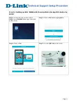
DSL-2750U
Brand: D-Link Pages: 3
DSL-2750U
Brand: D-Link Pages: 3

Premium
Brand: Majesti-Fi Pages: 2
AC1200
Brand: D-Link Pages: 2
DIR-868L
Brand: D-Link Pages: 3

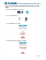
COVR-C1200
Brand: D-Link Pages: 24

DIR-868L
Brand: D-Link Pages: 59
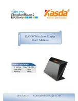
KA300
Brand: Kasda Pages: 42
MP980 series
Brand: Canon Pages: 4
DCS-5000L
Brand: D-Link Pages: 3
N300
Brand: D-Link Pages: 2
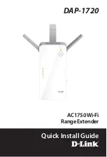
DAP-1720
Brand: D-Link Pages: 24
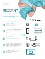
COVR-C1203
Brand: D-Link Pages: 6
DIR-850L
Brand: D-Link Pages: 13
COVR-2202
Brand: D-Link Pages: 2
SharePort DIR-825
Brand: D-Link Pages: 20
AirPlus DI-714P+
Brand: D-Link Pages: 5
AC5300
Brand: D-Link Pages: 12


