


Chapter 60 Port
GS2220 Series User’s Guide
467
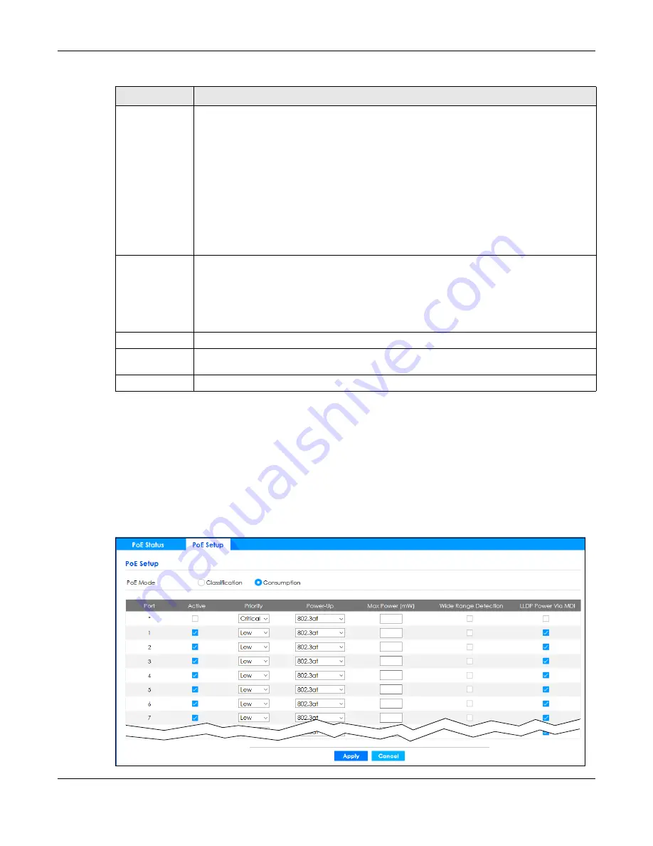
60.3 PoE Setup
Use this screen to set the PoE power management mode, priority levels, power-up mode and the
maximum amount of power for the connected PDs.
Click
Port
>
PoE Setup
>
PoE Setup
, the following screen opens.
Figure 354
Port > PoE Setup > PoE Setup
Class
This shows the power classification of the PD. Each PD has a specified maximum power that fall
under one of the classes.
The Class is a number from 0 to 4, where each value represents the range of power that the
Switch provides to the PD.
Each class corresponds to a default maximum power that can be extended in
Port
>
PoE Setup
>
PoE Setup
to the following values.
•
Class 0
– default: 0.44 W to 15.4 W, can be extended to 17.8 W.
•
Class 1
– default: 0.44 W to 4 W, can be extended to 5.8 W.
•
Class 2
– default: 0.44 W to 7 W, can be extended to 9 W.
•
Class 3
– default: 0.44 W to 15.4 W, can be extended to 17.8 W.
•
Class 4
– default: 0.44 W to 30 W, can be extended to 32.8 W.
Priority
When the total power requested by the PDs exceeds the total PoE power budget on the Switch,
you can set the PD priority to allow the Switch to provide power to ports with higher priority first.
•
Critical
has the highest priority.
•
High
has the Switch assign power to the port after all critical priority ports are served.
•
Low
has the Switch assign power to the port after all critical and high priority ports are
served.
Power-Up
This field displays the PoE standard the Switch uses to provide power on this port.
Consuming
Power (W)
This field displays the current amount of power consumed by the PD from the Switch on this port.
Max Power (W)
This field displays the maximum amount of power the PD could use from the Switch on this port.
Table 244 Port > PoE Setup > PoE Status (continued)
LABEL
DESCRIPTION
Содержание GS2220-10
Страница 23: ...23 PART I User s Guide...
Страница 49: ...49 PART II Technical Reference...
Страница 425: ...Chapter 47 Access Control GS2220 Series User s Guide 425 Figure 327 Example Lock Denoting a Secure Connection EXAMPLE...
Страница 446: ...Chapter 55 Configure Clone GS2220 Series User s Guide 446 Figure 340 Management Configure Clone...
Страница 517: ...517 PART III Troubleshooting and Appendices...