


GS1915 Series User’s Guide
33
C
HAPTER
3
Hardware Panels
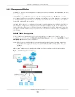
This chapter describes the front panel and rear panel of the Switch and shows you how to make the
hardware connections.
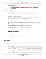
3.1 Front Panel Connections
The following figures show the front panels of the Switch.
Figure 10
Front Panel: GS1915-8
Figure 11
Front Panel: GS1915-8EP
Figure 12
Front Panel: GS1915-24E
Figure 13
Front Panel: GS1915-24EP
The following table describes the ports.
Table 5 Panel Connections
CONNECTOR
DESCRIPTION
8/24 1000Base-T RJ-
45 Ethernet Ports
These are 10/100/1000Base-T auto-negotiating and auto-crossover Ethernet ports.
Connect these ports to a computer, a hub, a router, or an Ethernet switch.
8/12 1000Base-T RJ-
45 PoE Ports
These are 10/100/1000Base-T auto-negotiating and auto-crossover Ethernet ports.
A PoE port is an Ethernet port that can supply power to a connected device.
Connect these
ports to a PoE-enabled IP camera / IP phone / AP, or an Ethernet switch.
Содержание GS1915 Series
Страница 17: ...17 PART I User s Guide ...
Страница 39: ...39 PART II Technical Reference ...
Страница 101: ...Chapter 8 Basic Setting GS1915 Series User s Guide 101 Figure 75 Basic Setting PoE Setup PoE Setup ...
Страница 209: ...GS1915 Series User s Guide 209 Figure 146 Advanced Application LLDP LLDP Local Status LLDP Local Port Status Detail ...
Страница 280: ...GS1915 Series User s Guide 280 Figure 206 Example Lock Denoting a Secure Connection EXAMPLE ...
Страница 309: ...309 PART III Troubleshooting and Appendices ...


