ZMC408SCAN Motion Controller Hardware Manual V1.5
3.10.2.
Basic Usage Method
1.
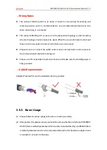
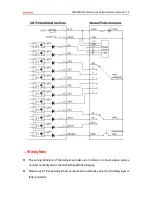
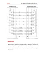
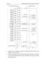
Refer to above handwheel wiring graphic, correctly connect the handwheel and
controller.
2.
After powered on, please select ETHERNET or RS232 or RS485 to connect to
ZDevelop.
3.
Configure axis No., if there is no default AXIS axis No. (axis 10, 11, 12, 13 are
recommended) of controller handwheel interface, remapped must be done.
Followings are processes.
BASE(target axis number)
‘the axis No. to be remapped
ATYPE(target axis number) = 0 ‘set axis type as 0
BASE(8)
‘handwheel interface initial axis No. is 8 (invalid)
ATYPE(8) = 0
‘set initial type of h
andwheel interface as 0
AXIS_ADDRESS(target axis number)=(-1<<16) + 8
‘bind initial axis 8 to target axis No.
ATYPE(target axis number) = 6
‘set
this new axis interface as required axis type, such as 3 or 6
4.
Configure IO: assign axis selection (HSX, HSY, HSZ, HSU) and ratio (HX1, HX10,
HX100) and emergency stop (HEMGN) functions as required. These signals are
essentially digital input signals with fixed numbers but no fixed functions. It
needs ZDevelop development (the axis selection is the connected axis of
“connect” synchronization motion, and the ratio is the “connect” ratio.
5.
When completed above steps, it can start to use handwheel.
BASIC Routine Reference:
ATYPE(4) = 0 ‘restore axis type of axis 10
ATYPE(8) = 0 ‘restore default handwheel axis type
AXIS_ADDRESS(4) = (-
1<<16)+ 8 ‘map the address of MPG manual pulse axis to axis 4
ATYPE(4) = 3
‘set manual pulse axis as quadrature encoder
type
UNITS(4) = 1 ‘set the unit as pulse for pulse amount of manual pulse axis
CONNECT(100,4) AXIS(0)
‘axis 0 connects to manual pulse axis at the synchronous ration of 100
Содержание ZMC408SCAN
Страница 1: ......
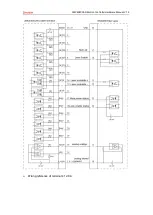
Страница 52: ...ZMC408SCAN Motion Controller Hardware Manual V1 5 Wiring reference of terminal s 12 DA...


