Barrier Gate-ProBG3000 Series
User Manual
P a g e
| 4
Copyright©2020 ZKTECO. CO., LTD. All rights reserved.
2.2
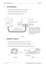
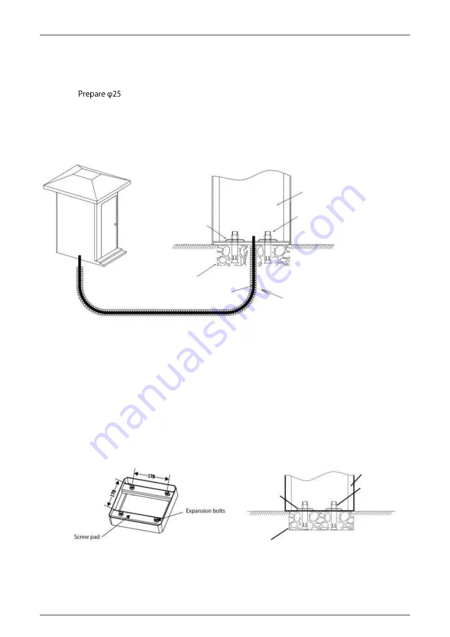
Cable Embedding
•
thick protective sleeve and cable in advance.
•
Connect the Route cables through protective sleeves.
•
Use a tool to open a cable tray on the ground.
Fig. 2.1
2.3
Installation Procedure
•
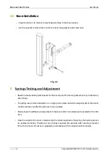
Use a screw pad to mark the installation position of the cabinet.
•
Drive four expansion bolts into the bolt holes, as shown in Fig. 2.2.
•
Install screw pads and use a spanner to tighten nuts, as shown in Fig. 2.3.
Fig. 2.2
Fig. 2.3
Chassis
Control
Room
Screw Pad
Base concrete
A standard power wire RVV3*1.0
Expansion
bolt 4-M12
Concrete Base
Ground
Cabinet
Ground
Screw pad
Expansion Bolt 4-M12
Ground
Ground
The power wire is wrapped and
protected using the wire sleeve
when laid out under the
ground (the strong current
should be separated from the
weak current).


