INSTALLATION AND OPERATING INSTRUCTIONS:
2-jaw parallel gripper, electric, GEP2000 series
INSTALLATION AND OPERATING INSTRUCTIONS:
2-jaw parallel gripper, electric, GEP2000 series
7
Zimmer GmbH
•
Im Salmenkopf 5
•
77866 Rheinau, Germany
•
+49 7844 9138 0
•
+49 7844 9138 80
•
www.zimmer-group.com
EN / 2021-07-08
DDOC01113-01 / a
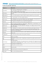
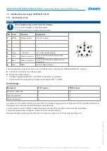
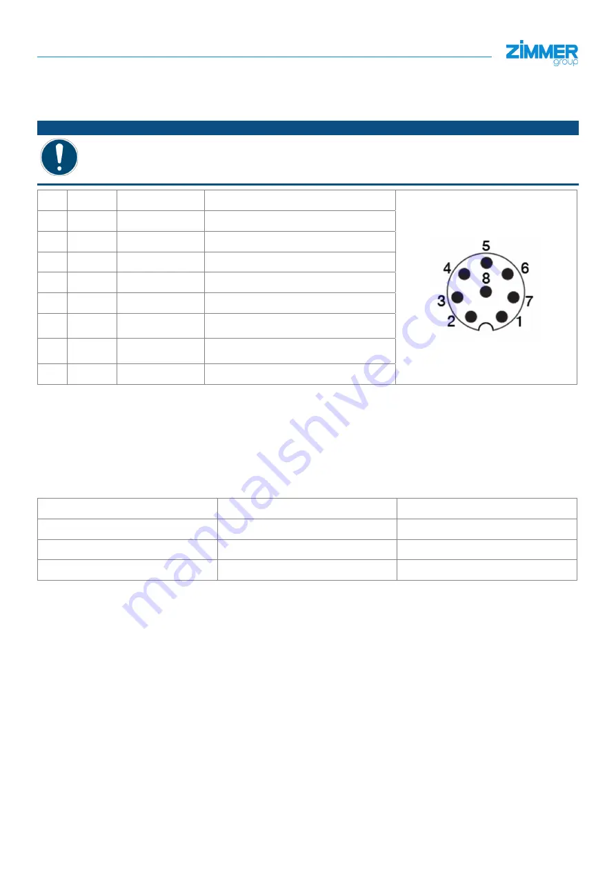
7.2 Installing the power supply "GEP20xxIO-12-B-01"
7.2.1 Installing the wiring
NOTICE
Non-compliance may result in material damage.
A correct pin assignment must be ensured.
Ö
The product may be ruined and malfunction.
PIN Color
Function
Explanation
1
White
Analog output
0 to 10 V output
2
-
-
-
3
-
-
-
4
-
-
-
5
Gray
+ 24 V DC
+ 24 V DC supply voltage
6
Pink
Move command
Input, control input for inward move
command
7
Blue
Move command
Input, control input for outward move
command
8
Red
GND
0 V DC supply voltage
The following steps must be carried out for commissioning or installing the "GEP20xxIO-12-B-01" product:
►
Connect the product to the voltage supply.
►
Secure the voltage supply.
Ö
A voltage supply between PIN 5 and PIN 8 is necessary for operation.
Ö
A jaw movement is triggered by a voltage level between PIN 7 or PIN 6.
Control logic:
Movement
PIN 7 (open)
PIN 6 (close)
Product in rest mode
0
0
Open the product
1
0
Close the product
0
1
A movement in the desired direction occurs when the corresponding signal is at a high level. After a high level is detected,
the gripper movement occurs until the gripping process ends.
It is important to ensure that the corresponding signal is reset after successful movement has taken place.
This must happen before a signal is carried out in the opposite direction.
Between withdrawing the signal and the next command, a pause time of 10 ms must be adhered to.


