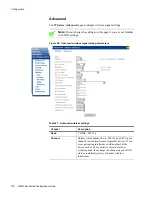
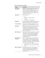
background image

Configuration

116

zNID 24xx Series Configuration Guide


802.1x

802.1X network requires mutual authentication between a client station and 
the router by including a RADIUS-based authentication server. Information 
about the RADIUS server such as its IP address, port and key must be entered. 
WEP encryption is enabled by default with default encryption strength and 
network keys.

See 

RADIUS authentication, page 125

.

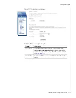
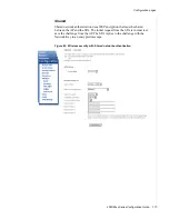
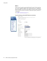
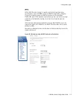
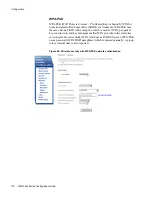
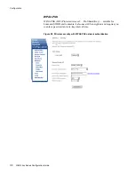
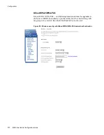
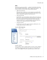
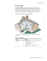
Figure 84:  Wireless security with WPA network authentication

Содержание zNID-GE-2402

Страница 1: ...zNID 24xx Series Configuration Guide For software version 2 5 x August 2012 Document Part Number 830 03782 01 ...

Страница 2: ...tic manual or otherwise or disclosed to third parties without the express written permission from Zhone Technologies Inc Bitstorm EtherXtend EZ Touch IMACS MALC MXK Raptor SLMS Z Edge Zhone ZMS zNID and the Zhone logo are trademarks of Zhone Technologies Inc Zhone Technologies makes no representation or warranties with respect to the contents hereof and specifically disclaims any implied warrantie...

Страница 3: ...terface 15 zNID 24xx series components 16 zNID 24xx models and interfaces 17 GPON models 17 Gigabit Ethernet models 17 Chapter 2 Management 19 Management interfaces 19 CLI 19 Web 19 SNMP 20 OMCI 20 OMCI vs Residential Gateway management 21 Comparing RG OMCI and VEIP by service traffic forwarding 22 RG 22 OMCI 22 Dual Managed 22 RG configured flows 22 OMCI configured ONU flows 24 OMCI unique featur...

Страница 4: ...t interface 33 DNS 34 DNS client 34 DNS Proxy Server 36 Internet time 37 System log 39 Power shedding 42 Backup Restore 43 Backup 43 Restore 45 Restore default 46 SNMP agent 47 TR 069 Client 49 Certificates 51 Local certificates 52 Trusted CA 53 Software 54 Restore software 54 Update software 55 Reboot 56 Status and statistics 57 Device info 58 Statistics 61 LAN interface status 65 GPON interface ...

Страница 5: ...d 101 Brouted 102 PPPoE 103 Ethernet 104 GPON 106 Rate Limits 107 Wireless 108 Basic 108 Security 110 MAC filter 126 Wireless bridge 127 Advanced 130 Voice 134 SIP 135 SIP PLAR 136 MGCP 139 Lines 140 VLAN 143 Settings 143 Modes 151 WAN backup 153 Deployment scenarios 156 IP configuration options 157 Creating data connections 162 Creating bridge connections 163 Creating routed connections 166 Creat...

Страница 6: ...ged LAN ports 198 Tagged uplink port and tagged LAN ports 200 S Tagged 200 TLS mode 202 NAT and DHCP 205 DHCP server 209 Data services 210 Rate limiting 210 Priority 211 Chapter 4 Special scenarios 213 Microsoft Media Room support 213 Any port any service 217 Chapter 5 Troubleshooting tests 219 Diagnostics 219 Ping 221 Trace route 222 Voice 223 Hardware reset 224 Index 225 ...

Страница 7: ...injury or death Carefully read and follow the instructions included in this document Caution A caution alerts users to conditions or actions that could damage equipment or data Note A note provides important supplemental or amplified information Tip A tip provides additional information that enables users to more readily complete their tasks WARNING A warning alerts users to conditions or actions ...

Страница 8: ...th the zNID but are also available on the Zhone website Refer to the release notes for software installation information and for changes in features and functionality of the product if any Bold Used for names of buttons dialog boxes icons menus profiles when placed in body text and property pages or sheets Also used for commands options parameters in body text and user input in body text Fixed Use...

Страница 9: ...nd zNIDs GigE Gigabit Ethernet GPON Gigabit passive optical network HPNA Home phone line networking alliance IPTV Internet protocol TV LED Light emitting diode MALC Multi access line concentrator MDU Multiple Dwelling Unit MIB Management information bases MoCA Multimedia over Coax Alliance OLT Optical Line Terminator OMCI ONU Management and Control Interface ONT Optical Network Terminator ONU Opti...

Страница 10: ...gh there are a number of differences between the North American T1 and the European E1 UPC Ultra physical contact for fiber connector Wi Fi Wireless local area network trademark of Wi Fi alliance VoIP Voice over IP zNID Zhone Network Interface Device ZMS Zhone Management System Table 1 Acronyms and their descriptions Continued Acronym Description ...

Страница 11: ...al support Technical Support for this product is provided by your Internet Service Provider Important safety instructions Read and follow all warning notices and instructions marked on the product and included in the Hardware Installation Guide available at Zhone com ...

Страница 12: ...About This Guide 12 zNID 24xx Series Configuration Guide ...

Страница 13: ...y by the ZMS using the EZ Touch management feature The zNID is a full featured gateway supporting services such as DHCP server rate limiting filtering comprehensive logging and more The zNID product line implements a very flexible QoS allowing the service provider to guarantee that services are being prioritized correctly and the end user receives the Quality of Experience that is expected All 24x...

Страница 14: ...d zNID management application Zhone Management System ZMS Web HTTP Command Line Interface CLI Telnet SSH ONT Management Control Interface OMCI for GPON only More information about management capabilities see Management on page 19 and Logging in to the 24xx series zNIDs on page 29 For information about special configurations such as Microsoft Media Room and Any Port Any Service see Chapter 4 Specia...

Страница 15: ...members of each VLAN The type of connection is also displayed in the lower table The upper table shows the port defaults Figure 1 shows the default state of the zNID 24xx To read the Configuration VLAN Settings page see Factory default VLAN definition on page 87 and Edit Port Defaults on page 145 To understand more about VLAN options see VLANS on page 197 To create bridged routed or PPPoE connecti...

Страница 16: ...els and interfaces on page 17 for information on which models support which interfaces Figure 2 The interfaces displays and buttons for the zNID 24xx Depending upon the zNID model selected the interfaces on the zNID can include One two or four Gigabit Ethernet RJ45 ports Two Phone Ports POTS One Coax Port with RF Video USB port To reset the zNID 24xx 1 Press a pin into the reset button and hold it...

Страница 17: ...dels have the following interfaces Model Description zNID GPON 2402 GPON Uplink 2 GigE zNID GPON 2403 GPON Uplink 2 GigE RFV zNID GPON 2424 GPON Uplink 2 POTS 4 GigE zNID GPON 2425 GPON Uplink 2 POTS 4 GigE RFV zNID GPON 2426 GPON Uplink 2 POTS 4 GigE WiFi USB zNID GPON 2427 GPON Uplink 2 POTS 4 GigE WiFi RFV USB Model Description zNID GE 2402 GE Uplink 2 GigE zNID GE 2424 GE Uplink 2 POTS 4 GigE ...

Страница 18: ...zNID 24xx Series 18 zNID 24xx Series Configuration Guide ...

Страница 19: ... device uses VLAN 7 as the default management VLAN with DHCP Client enabled This allows the ONU to automatically obtain an IP address when connected to an MXK CLI The zNID 24xx products can be managed using a command line interface Web The zNID 24xx products can also be fully managed through the web HTTP interface The web pages are very intuitive and they include a context sensitive help button fo...

Страница 20: ...l Interface OMCI provides policy based configuration and management capabilities for GPON OMCI management is intergrated into the OLT command set so configuration of the ONU with OMCI is done from the OLT not directly as with the Web UI or CLI interfaces Not all modules in the zNID such as the wireless interface can be configured directly from OMCI however they may be used with OMCI via the Virtua...

Страница 21: ... by the zNID provides a broad base of routing options See IP configuration options page 157 for more information The RG interface supports wireless and VoIP options for SIP SIP PLAR and MGCP See Voice page 134 and Creating voice connections page 191 for more information about Voice Most of this document explains the RG Web UI interface RG only mode is also called RG or RG mode OMCI only Data flows...

Страница 22: ...switching no routing WiFi is not supported in OMCI only mode Voice can operate as an OMCI configured function or an RG configured function RG configured flows and OMCI configured flows can co exist but Voice must be OMCI configured Remember the following rule OMCI always wins See OMCI configured ONU flows on page 24 for more information Dual Managed Dual Managed connections mapped to the VEIP conn...

Страница 23: ...arding switch determines where to send See VLANS on page 197 for a discussion of layer 2 forwarding behaviors Figure 3 Remote Gateway configured flows GEM ports in the 5xx 6xx range are reserved for Residential Gateway traffic flows By default all RG VLANs map to the 5xx RG GEM This mapping is not configurable and does not require any OMCI provisioning action to create the 5xx GEM on the 24xx unit...

Страница 24: ...ownstream packets that arrive on each GEM are classified based on the classification rules that have been created by OMCI provisioning actions Packets that match a Classification Rule are Modified as specified by that rule and Forwarded to the egress port specified by that rule Packets that are not classified are dropped blocked Exception packets that require CPU analysis like the IGMP joins and l...

Страница 25: ...affic and the same 1 1 mapping of UNIs to GEMs is required for handling of uni cast traffic VLAN Translation is supported for the IP TV application as long as all Ethernet Ports are members of the same original VLAN It is not possible to translate a single downstream multicast video packet to VLAN A for sending out eth 1 while simultaneously translating the same packet to VLAN B for sending out et...

Страница 26: ...I Voice Packet Log Audit Log and Line Status Accessible via Telnet CLI or Web GUI Ethernet Port Statistics are provided Accessible via OMCI Telnet CLI or Web GUI GPON physical layer statics are provided Accessible via OMCI Telnet CLI or Web GUI There is no Bridge Table to show learned MACs for any OMCI configured flows Reserved GEM ports When using any configuration mode GEM ports in the 0xx 1xx a...

Страница 27: ...VLAN Identifier When the eth0 interface of an RG VLAN is configured as an OMCI member it will be automatically mapped to the VEIP Conversely when eth0 is configured as a tagged or untagged member of the VLAN it is automatically mapped to the default 5xx RG GEM Up to 24 RG VLANs are supported and all 24 of them could be mapped to the VEIP Each RG VLAN must have a unique VLAN ID However VLAN transla...

Страница 28: ... Filter Rules provisioned on the VEIP with a matching Original VLAN ID then the RG VLAN will not have a connection into the network The VEIP provides mapping of RG VLANs to one or more additional GEMs beyond the default 5xx RG GEM This mapping enables upstream traffic prioritization via GPON Traffic Profile GTP parameters on a per VLAN basis It also provides VLAN translation and promotion features...

Страница 29: ...pically 192 168 1 100 is used Of course if you change the IP address of the ONU you will lose connectivity You would then need to reconfigure your PC to be on the same subnet The default login is admin and the default password is zhone Note For security reasons the password should be changed from the default password To change the password see User names and passwords on page 31 Logging in with CL...

Страница 30: ...er shedding which cuts power to non voice services during power outages so essential voice services may be provided for as long as possible on battery power Figure 7 The System menu This section describes the following System pages Management access control on page 31 Default interface on page 33 DNS client on page 34 Internet time on page 37 System log on page 39 Power shedding on page 42 Backup ...

Страница 31: ...well as update the ONU s software The password can be up to 16 characters User names and passwords Use the fields in the Access Controls Password to enter up to 16 characters and click Apply Save to change or create passwords Note Passwords cannot contain a space The user name admin has unrestricted access to change and view configuration of your Zhone Router The user name support is used to acces...

Страница 32: ...rogrammed in the OLT The system administrator should have programmed this value Changing the value will disable communications with the network The unit will reset once the Reg ID has been changed and the GPON link will not communicate with the OLT until the same password is entered in the OLT Figure 9 The Registration ID is given from the service provider ...

Страница 33: ...l be used as the source address This device has many internal applications such as SNMP DHCP DNS PING If one of these applications sends a packet to an IP address which is not defined in the route table and the application has not been directed to use a particular interface to transmit the packet then the default interface s IP address will be used as the source address and routing will be resolve...

Страница 34: ...ription DNS Client Source Static requires a Primary and or a Secondary DNS address to be entered DHCP requires an existing VLAN to be selected as the DHCP source PPPoE requires an existing PPPoE tunnel to be selected as the PPPoE source OMCI The DNS Server IP addresses which are provided via OMCI will be used Primary DNS The IP address of the Primary Domain Name Server Secondary DNS The IP address...

Страница 35: ...System features zNID 24xx Series Configuration Guide 35 Figure 12 Static as DNS Client Source Figure 13 PPPoE as DNS Client Source ...

Страница 36: ...es a Proxy DNS Request using its System DNS Client then generates a corresponding DNS response to the LAN side client with the corresponding IP Address learned via the Proxy Request Figure 14 Displaying the DNS Proxy Server default shown The Host Names of locally attached devices are dynamically learned and automatically populated in the DNS Proxy Table Domain Names must be statically configured T...

Страница 37: ...e servers If no time server can be found the system will default to January 1 The system allows for up to five time servers to be configured If the first server is unreachable the ONU will try the next server If that is not available it will try the next one and so on The configuration of the time client is shown below Figure 16 Internet time settings Table 3 Internet time settings UI Label Descri...

Страница 38: ... Fourth NTP time server Select the fourth NTP time server to access from the pull down list or select other and configure the IP address Fifth NTP time server Select the fifth NTP time server to access from the pull down list or select other and configure the IP address Time zone offset Select the GMT offset from the pull down list Table 3 Internet time settings UI Label Description ...

Страница 39: ...eter Mode determines where the messages will be stored The local messages can be stored in RAM or they can be stored in a file for later review or they can be sent to a remote syslog server Only one remote server is allowed The priority of the messages is selected by a separate parameter Figure 17 Configuring the system log Table 4 System log message severity levels Message severity Description 0 ...

Страница 40: ...m messages Log Level System Log messages have different priorities All messages of the selected priority and higher will be placed in the system log 0 Emergency 1 Alert 2 Critical 3 Error 4 Warning 5 Notice 6 Informational 7 Debugging Display Level Determines the priority level of System Log messages that will be displayed via the GUI which makes it easy to filter the maximum priority of messages ...

Страница 41: ...end Syslog events to a remote Syslog server Local Buffer and Remote Syslog Local RAM remote server Local File Not currently supported Local File and Remote Syslog Not currently supported Server IP Address If remote IP address of the Remote Log Server Server UDP Port If remote the UDP port for the syslog protocol Default is 514 Table 5 Configure system log UI Label Description ...

Страница 42: ...wer shedding feature is only activated when a UPS is connected to power the ONU and signals from the UPS indicate that the ONU is actually being powered from the battery Figure 18 Configuring power shedding Table 6 Power shedding options UI Label Description Shutdown Delay Shutdown delay defines the amount of time in minutes the ONU waits after an AC power outage which will force the ONU to batter...

Страница 43: ... Backup Restore Backup page will cause the current configuration to be saved on your PC The configuration is saved under the file name backupsettings conf in a folder determined by your browser s download settings It is strongly suggested that filename be changed to more meaning full name that contains the date or the IP address or the system name of the ONU Appropriate naming of the file will be ...

Страница 44: ...Management 44 zNID 24xx Series Configuration Guide Figure 20 Saving the backup configuration file ...

Страница 45: ...creen allows you to restore the ONU to a operate with a previously saved configuration Click Browse in the Backup Restore Restore screen then select the saved configuration and click open Figure 21 Restoring from a saved configuration Figure 22 Waiting while the router is being updated ...

Страница 46: ...to the zNID factory default configuration Click Restore Default Settings close the browser window and wait for the router to reboot If the IP address had been changed from the default IP address you will need to follow the log in directions Logging in to the 24xx series zNIDs on page 29 Figure 23 Restoring to the factory defaults ...

Страница 47: ...eature The ONU will not send traps or respond to set or get messages Read Community Enter the read community name in the input box This allows read access from SNMP clients This field is 32 characters in length and defaults to public Set Community Enter the write community name in the input box This allows read write access from SNMP clients This field is 32 characters in length and defaults to Zh...

Страница 48: ...s where traps are sent Currently there is only 1 trap manager allowed Trap Filters The following are a list of SNMP Traps When Disable the traps will not be sent Cold Start The ONU was Powered Off and On Warm Start The software was rebooted Authentication Trap Three failed attempts in a row try to log into the box Link Up Down Trap A physical interface lost connectivity to its remote peer Enterpri...

Страница 49: ...terval Periodic interval in seconds at which Inform messages will be generated ACS URL Web site address of the ACS e g http zhone com 6050 If the URL includes a domain name a DNS must be reachable to resolve the domain name ACS User Name User name required to access the ACS ACS Password ACS Password User password required to access the ACS Bound Interface Name Select the name of an interface to be...

Страница 50: ... Request User Name and Password Connection Request User Name User name required to authenticate an ACS Connect Request message Connection Request Password Password required to authenticate an ACS Connect Request message Connection Request URL Connect Request source address used when responding to an ACS Connect Request message This field is not configurable GetRPCMethods Sends an RPCMethod message...

Страница 51: ...y code S State L Locality O Organizational Name OU Organizational Unit Name CN Common Name email address Type Certificate types are request signed or ca A cer tificate request is one that has not been signed by a Certificate Authority CA A signed certificate is one that has been signed and may be used to verify the identity of the device with a peer A ca certifi cate is a Certificate Authority s c...

Страница 52: ...s to verify your identity when establishing a connection to a server or client over the secure socket layer SSL The System Certificates Local screen allows you to add view or remove Local certificates for the system A maximum of four Local certificates can be stored Figure 26 The Certificates Local screen ...

Страница 53: ...d to verify peer s identity when establishing a connection to a server or client over the secure socket layer SSL The Certificates Trusted CA screen allows you to import or view Trusted CA certificates for the system A maximum of four Trusted CA certificates can be stored Figure 27 The Certificates Trusted CA screen ...

Страница 54: ... ONU reboots the system will update its display of current and alternate Software versions automatically The configuration remains unchanged In other words you do not need to reconfigure the ONU after completing the restore procedure Clicking Reload software will cause the unit to reboot as it switches to the newly active software This will happen immediately after clicking no extra warning messag...

Страница 55: ...r s PC Then select the configuration file that you would like to use to upgrade the ONU Clicking Update Software will cause the software on the ONU to be updated with the selected software image The ONU will then reboot The ONU will verify that the software image is of the appropriate type and will reject the file if it is not compatible Figure 29 Updating software ...

Страница 56: ...Reboot will cause the unit to re initialize as if it was power cycled This will happen immediately after clicking no extra warning message is provided Close the browser window and wait to reconnect to the router Figure 30 Rebooting the zNID Figure 31 Rebooting message ...

Страница 57: ...ork issues The zNID 24xx provides Device info on page 58 Statistics on page 61 LAN interface status on page 65 GPON interface status on page 66 PPPoE status on page 68 Route on page 69 ARP table on page 70 Bridge table on page 71 DHCP status on page 72 IGMP on page 73 OMCI on page 74 Wireless on page 78 Voice on page 79 Figure 32 The Status menu ...

Страница 58: ...e is a user definable name which can be used to identify the ONU System Name can be set in System info page 90 System Location System Location is user definable information to help identify the ONU and the location of the ONU System Location can be set in System info page 90 System Location is the MIB 2 object sysLocation System Contact System Contact is user definable information to help identify...

Страница 59: ...mber Serial Number Registration ID The identification number entered when the ONU is to be registered using the Reg ID programming procedure described in the Release Notes FSAN A number that uniquely identifies the device on the PON to the OLT Bootloader Version Level of firmware used to load the ONU This information can be useful when troubleshooting Firmware Version Level of firmware actively ru...

Страница 60: ...Management 60 zNID 24xx Series Configuration Guide Figure 35 MAC addresses are shown for each port Figure 36 Alarms example with no alarms presently showing ...

Страница 61: ...occurring Table 11 LAN side statistics UI Label Description Received Bytes The number of ingress bytes into the interface since statistics were last reset This is the data coming into the ONU from an external source Received Frms The number of ingress frames into the interface since statistics were last reset This is the data coming into the ONU from an external source Received Errs The number of ...

Страница 62: ...ata going to an external device Transmitted Errs The number of frames that could not be transmitted from the interface due to framing errors since statistics were last reset Transmitted Drops The number of egress frames that were dropped not transmitted due to addressing errors or memory limitations since statistics were last reset Table 11 LAN side statistics UI Label Description Table 12 GPON GE...

Страница 63: ... frames dropped due to congestion Accepted Multicast Frames Number of multicast frames accepted by the Multicast Filtering Function IPTV is generally multicast Dropped Multicast Frames Number of multicast frames dropped by the Multicast Filtering Function Table 13 GPON GTC GPON Transmission Convergence Statistics counter UI Label Description BIP Errors Bit Interleaved Parity Errors FEC Corrected C...

Страница 64: ...LOAM messages with ONU ID matching this ONU s ID Broadcast Received Messages Number of CRC correct broadcast downstream PLOAM messages Discarded Received Messages Number of downstream PLOAM messages discarded because the message is unknown and not registered or because the message is not valid in the current state Non standard Received Messages Number of non standard downstream PLOAM messages rece...

Страница 65: ...net status UI Label Description Admin State Up Port is enabled and a link has been established Down Port is disabled administratively down NoLink Ethernet Port is enabled but no device is connected Max Bit Rate Shows the bit rate of the physical layer 10 10 Mbps 100 100 Mbps 1000 1 Gbps Duplex Mode Full or Half Duplex Pause Enable Port will transmit pause frames to an attached device when there is...

Страница 66: ... Label Description Current Link State Up link is active Down link is not communicating Link Up Transitions Number of times the Link has transitioned from down to up ONU ID Optical Network Unit ID ONU State Optical Network Unit State OPERATIONAL is active RF Video State Indicates interface is enabled or disabled Receive Level The optical receive level in dBm Transmit Power The optical transmit leve...

Страница 67: ...e inability to properly adjust Loss of Signal No input signal detected Make sure fiber is plugged in Loss of Link The link has been lost Loss of Frame Framing has been lost GEM LCD Loss of GEM Channel Delineation Failed Signal Bit Error Rate exceeds 10E 5 Degraded Signal Bit Error Rate exceeds 10E 6 Msg Error Msg Unknown PLOAM message received Deactivated Received Deactivate on ONU Disabled Disabl...

Страница 68: ...ted for this interface Figure 42 PPPoE status Table 18 PPPoE status UI Label Description Interfaces Name of the PPP Uplink Interface Interface Type Bridged or Routed Status Current status of the PPP protocol Uptime Duration that the PPP protocol has been connected Current MTU The current Maximum Transmission Unit size Last Error Code Last Error encountered Connect Button Connect or reconnect Disco...

Страница 69: ...ion of the address The 255 in an octet masks all information from that octet Flag U Route is up and available for use Rejecting route all packets to this network are dropped G Specified Gateway should be used for this route H Host R Reinstate D Dynamically installed route table entry M Modified route table entry typically by ICMP redirect Metric Defines the Number of Hops to reach the destination ...

Страница 70: ...vice discovered on the interface listed in the device column Flags Complete Both IP and MAC address have been resolved Permanent Statically configured ARP entry Publish Proxy ARP entry Incomplete IP or MAC but not both HW Address MAC address of the device discovered on the interface listed in the device column Device The Bridge interface or logical VLAN interface of the internal layer 2 bridge on ...

Страница 71: ...u an idea of the number of devices that are seen on the network Figure 45 Bridge table Table 21 The VLAN Bridge table UI Label Description VLAN ID The Bridge interface or logical VLAN interface of the internal layer 2 bridge on which the device was discovered MAC Address MAC address of the discovered device Interface Name The Linux Interface Name for the port on which the MAC address was discovere...

Страница 72: ... is configured there is a page Status DHCP Bindings which shows the permanently assigned IP address Table 22 Table of DHCP Leases given out by the internal DHCP Server UI Label Description Interface Name of the interface or virtual interface that received a request for an IP address from the internal DHCP server Host Name Name of the device that requested an IP address from the internal DHCP Serve...

Страница 73: ...See Creating video connections on page 190 for configuration information Figure 47 The group membership table for IGMP Table 23 Table of IGMP group members UI Label Description Group Address Multicast IP group address Reporter IP The IP address of the host in the multicast group Reporter MAC The MAC address of the host in the multicast group Interface The Interface which discovered the multicast g...

Страница 74: ...ID number assigned by the OLT for this instance of an OMCI configured GPON Bridge UNI Port The UNI port Ethernet VOIP VEIP that is associated with this Bridge ME GEM Port The GEM port on the GPON link that is associated with this Bridge ME GEM Video Optional The Multicast GEM port on the GPON link that is associated with this Bridge ME Untagged VLAN The default tag that will be applied on ingress ...

Страница 75: ...e all VLAN IDs are allowed to pass through Table 24 OMCI mapping information for bridged interface UI Label Description Table 25 OMCI mapping information for routed interface UI Label Description Host ME The instance of the OMCI configured IP Host IP Option The IP Address Mode for this IP Host instance Choices are Static and DHCP IP Address The IP Address assigned to this IP Host or acquired via D...

Страница 76: ...ul for debug of OMCI related configuration issues Figure 50 OMCI mapping information for VLANS Table 26 OMCI mapping information for VLANS UI Label Description Port The Physical and Virtual User to Network Interfaces that are configurable via OMCI ManagedEntity ID The OMCI instance of the UNI Admin State When configured Down the port is unusable Must be configured Up for normal operation This is c...

Страница 77: ...it uses SNMP to create the RG side of the VEIP Figure 51 OMCI mapping information for VEIP mapping Table 27 Table of IGMP group members UI Label Description VLAN ID The VLAN Tag for this flow VLAN Name The VLAN Name as defined by the user for this VLAN ID Connection Type Bridged Routed PPPoE Bridged PPPoE Routed and Bridged CPU are types of VLAN connections Secure Forwarding Enabled will result in...

Страница 78: ...cated wireless stations UI Label Description MAC The MAC address of the authenticated wireless station Associated The wireless station has been associated with the access point Authorized The wireless station is an authorized user of the access point The wireless station has successfully completed the authentication process SSID The SSID of the of the zNID s access point Interface The interface of...

Страница 79: ...oing calls with date time duration of call and phone number and can be used to see calling activity and confirm normal operation Figure 53 Status and statistics for voice lines Table 29 Table of VoIP lines status and statistics UI Label Description Status Admin State Configured State Phone Number Configured Phone Number in SIP mode Registration Status Current Registration status with the Switch Ca...

Страница 80: ...g Calls The statistics provided refer to the previous completed call Received A connect command was received from the Switch and the call is in Receive Only mode so that the phone can ring Answered A connect command was received from the Switch and the call is in Send and Receive mode Connected A Disconnect that had one or more Packets Received Failed A Disconnect that had no Packets Received Outg...

Страница 81: ...P statistics UI Label Description Cumulative Cumulative statistics are kept across call Packets Sent The cumulative count of data bytes in the packets sent to the network Bytes Sent The cumulative count of data bytes in the packets sent to the network Bytes Received The cumulative count of data bytes in the packets received from the network Packets Lost The number of packets not received based upo...

Страница 82: ...fer ms The greatest delay an RTP packet had passing through the Jitter buffer Average Jitter Buffer ms The average delay an RTP packet had passing through the Jitter buffer Round Trip Delay ms The two way network delay Peak Round Trip Delay ms The worst two way network delay Overruns Number of packets received that could not be sent to the Jitter buffer since it was full Underruns The number of ti...

Страница 83: ...Device info zNID 24xx Series Configuration Guide 83 Figure 55 Voice status logs Figure 56 View packet log ...

Страница 84: ...Management 84 zNID 24xx Series Configuration Guide Figure 57 View audit log ...

Страница 85: ...vices such as rate limiting and other Network Address Translation NAT and DHCP services Deployment scenarios page 156 Creating data connections page 162 Creating bridge connections page 163 Creating routed connections page 166 Creating brouted connections page 172 Creating PPPoE tunnels page 179 Creating wireless connections page 188 Creating voice connections page 191 Advanced features on page 19...

Страница 86: ...type and number of interfaces depends on the model of the zNID See zNID 24xx models and interfaces on page 17 for more information Ethernet port The ONU has a default IP address of 192 168 1 1 on the LAN Ethernet ports The user can connect a standard PC to the LAN ports eth1 eth4 and configure the ONU using a standard web browser The PC will need to have an IP address on the same subnet Typically ...

Страница 87: ...bit Ethernet interfaces have the Port VLAN ID PVID set to 200 by default VLAN 200 the default data VLAN is also set as the PVID for the wireless SSID 0 wl0 Figure 58 Default VLAN and port interface settings For more information about PVID see Edit Port Defaults on page 145 Figure 59 shows how the default interfaces from Figure 58 and Figure 31 are displayed in the Web UI Table 31 Factory default V...

Страница 88: ...aces as displayed in the Configuration VLAN Settings page The VLAN to associate with the POTS interfaces is the Bound Interface Name parameter in the Configuration Voice SIP page or the Configuration Voice MGCP pages The POTS interfaces are not show on the Configuration VLAN Settings page ...

Страница 89: ...following pages of the Web user interface System info page 90 Static route page 91 Access control page 92 Firewall page 94 Interfaces page 100 Wireless page 108 Voice page 134 VLAN page 143 WAN backup page 153 See Deployment scenarios page 156 for procedures for the different scenarios which can be configured using these configuration pages Figure 60 The configuration menu ...

Страница 90: ...ation Table 32 Device Info page display UI Label Description System Name System Name is a user definable name which can be used to identify the ONU The System Name is used in the banner for the Web User Interface for the ONU System Name is the MIB 2 object SysName System Location System Location is user definable information to help identify the ONU and the location of the ONU System Location is t...

Страница 91: ... UI Label Description Destination IP address The IP address of the destination device This field will accept an IP address n notation where the n represents the number of bits for creating a network mask For example a net mask of 255 255 255 0 is 24 bits and would be designated by a 24 Interface The LAN interface for the static route Gateway IP Address The IP address of the default gateway for the...

Страница 92: ...e allowed in on an interface disabled black list and white list An interface may only have one of the three listing options Black list defines a set of source IP addresses MAC addresses which will not be allowed All other packets will be allowed White list defines a set of source IP addresses MAC addresses which will be allowed All other packets will be blocked Disabled allows all packets frames T...

Страница 93: ...erface to change Rule Name A required user defined identifier for the rule This identifier must be unique per interface rule Source IP Address Prefix The IP address or subnet to filter If the Prefix is 32 then the whole address is used Otherwise the prefix indicates the subnet to filter against Example 192 168 1 0 24 would filter against the 192 168 1 subnet Protocol Select either ICMP IGMP TCP or...

Страница 94: ...r the rule 4 Click Add Rule Firewall The firewall in the zNID 24xx provides protection against unwanted intrusion Global The Firewall Global page mainly enables the firewall options management access and port forwarding The Firewall dropdown must have Enable selected for management access and port forwarding to be active Figure 66 Top level firewall options Syn Cookie Protection protects against m...

Страница 95: ...Allowed on the interface The firewall global option must be enabled before this screen will take effect Figure 67 Firewall management port access table Table 35 Management services UI Label Description Interface The VLAN interface HTTP Web Browser Traffic PING ICMP Echoes used to test for connectivity SNMP Simple Network Management Protocol SNMPTRAP Alarms for Simple Network Management Protocol SS...

Страница 96: ...he Delete Rule s button allows one or more rules to be removed from the ONU The bottom table reflects the values that have been configured Configuration Interfaces Routed or Configuration Interfaces PPPoE for the selected interface The table is refreshed when a new interface is selected Figure 68 The table at the top shows the current port forwarding rules Define the port forwarding rules at the b...

Страница 97: ... a DMZ rule because Range rules allow specific ports or groups of ports to be opened up Range indicates that any traffic on those ports will be sent to the private IP address Remap Remap indicates that any traffic on those ports will be sent to the private IP address at the private port Port Start Lowest value port number for the range Port End Highest value port number for the range This can be e...

Страница 98: ...all is set to Enabled on the Firewall Global page 2 In the Name text box enter a name for the rule 3 From the Type dropdown select the type of port forwarding rule 4 Enter the appropriate information for the rule depends on rule type 5 Click Add Rule Figure 69 DMZ rule Figure 70 Port forwarding range rule ...

Страница 99: ...Configuration pages zNID 24xx Series Configuration Guide 99 Figure 71 Port forwarding remap rule ...

Страница 100: ...direct traffic based on Ethernet Media Access Control MAC addresses MAC addresses are a unique address per physical device Routers are layer three devices which use IP Addresses to direct packets Bridges direct packets based on address information in the packets as well as information learned from the processing and directing of other packets The Interfaces Bridged page displays the bridged interf...

Страница 101: ...tically sorted and displayed in ascending VLAN ID order Routed The Internet Protocol IP is a network layer Layer 3 protocol that contains addressing information and some control information that enables packets to be routed IP is documented in RFC 791 and is the primary network layer protocol in the Internet protocol suite The Interfaces Routed page displays the routed interfaces which have been d...

Страница 102: ...nterface and a second for the Bridged LAN side interface A Brouted VLAN may have multiple LAN ports as members and all ports will use the same IP subnet So Brouted means that the LAN side is like a bridge but has a routed interface for the WAN side To create brouted interfaces see Creating brouted connections page 172 Figure 74 ...

Страница 103: ...PP is a direct connection where one device directly connects to another using the protocol PPPoE is a virtual connection usually called tunnel between two devices On the Configuration Interfaces PPPoE page you can add a PPPoE on a port by VLAN either as PPPoE Routed or PPPoE Bridged To create PPPoE tunnels see Creating PPPoE tunnels page 179 Figure 75 The PPPoE Interface Setup page To edit a route...

Страница 104: ...able Port is enabled and a link has been established Disable Port is disabled administratively down NoLink Ethernet Port is enabled but no device is connected Max Bit Rate The maximum possible bit rate of the physical layer 10 10 Mbps 100 100 Mbps 1000 1000 Mbps Auto Duplex Mode Full or Half Duplex Pause In Ethernet flow control a pause frame request stopping transmission so the receiving device c...

Страница 105: ... a physical down state when the WAN uplink has been down for 15 seconds This mechanism is used to signal to attached devices that they need to initiate a backup connection When the WAN uplink has been back up for 30 seconds the LAN port is re enabled to restore service Table 37 Ethernet settings UI Label Description ...

Страница 106: ...ide GPON The Interfaces GPON page allows you to enable RF video on models which support RF video Figure 77 RF video may be enabled or disabled For models which support RF video RF video may also be disabled to conserve power when RF video is not in use ...

Страница 107: ... of 8 starting at 104Mbps If the allowed inbound rate is exceeded pause frames are transmitted to the attached device It is recommended that the attached device is configured to obey pause frames to reduce overhead caused by TCP IP packet retransmission Outbound Rate limit outbound traffic The supported values are 1 1000Mbps 0 disables rate limit rate above 100Mbps must be increments of 8 starting...

Страница 108: ...urity measures such as defining authentication and encryption methods are described in Security on page 110 Figure 79 Basic AP configuration options Table 39 Basic wireless settings UI Label Description Enable Wireless Enables the wireless transceiver To pass traffic a VLAN must be associated with the wireless interface See Creating wireless connections on page 188 for creating wireless connection...

Страница 109: ...s optimization however WMM may provide slower performance for some applications SSID Service Set Identifier identifies the wireless LAN to clients The SSID is a customer definable name for the AP but must be unique BSSID Basic Service Set Identifier is a unique identifier which identifies the AP Essentially a MAC address for the AP and is not configurable Country Selects the channel set based on c...

Страница 110: ...ds and in the regular transmission of data once the client has successfully completed the authentication process Figure 80 Some WiFi authentication and encryption examples Wireless security basic options Table 40 on page 111 describes an overview of the security method and pointers to more detailed information for each security option Network Authentication parameters part 1 Table 41 on page 113 a...

Страница 111: ...ss security basic options UI Label Description Enable WPS With WPA PSK WPA2 PSK Mixed WPA2 WPA PSK or Open Network Authentication modes there is the ability to add clients via push button or by a STA PIN or AP device PIN See WPS page 123 Select SSID Selects the SSID to associate with the Network Authorization mode ...

Страница 112: ... sometimes referred to the personal edition rather than the enterprise edition See WPA PSK page 118 WPA2 WPA2 is an upgrade to WPA whose main enhancement is AES encryption though AES has since been added to WPA See WPA2 page 119 WPA2 PSK WPA2 PSK is enabled by default WPA2 PSK like WPA is mainly WPA2 without the authentication server See WPA2 PSK page 120 Mixed WPA2 WPA Mixed WPA2 WPA supports bot...

Страница 113: ...3 X X Network Key 4 X X RADIUS Server IP Address X X RADIUS Port X X RADIUS Key X X WPA Group Rekey Interval X X WPA WAPI Passphrase X X WPA WAPI Encryption X Table 42 Network Authentication parameters part 2 WPA2 WPA2 PSK Mixed WPA2 WPA Mixed WPA2 WPA PSK WEP Encryption X X Encryption Strength Current Network Key Network Key 1 Network Key 2 Network Key 3 Network Key 4 RADIUS Server IP Address X X...

Страница 114: ...uthentication process WEP encryption can also be added to provide secure communication between the wireless access point AP and the clients See WPS page 123 for information about WPS setup WEP Encryption page 124 for information about WEP Encryption setup Figure 82 Wireless security with Open network authentication WPA WAPI Passphrase X X WPA WAPI Encryption X X X X WPA2 Preauthentication X X Netw...

Страница 115: ...tion uses WEP encryption that must be shared between the AP and the STA The initial request from the STA is in clear text as is the challenge from the AP The STA replies to the challenge with the Network Key in an encrypted message Figure 83 Wireless security with Shared network authentication ...

Страница 116: ...and the router by including a RADIUS based authentication server Information about the RADIUS server such as its IP address port and key must be entered WEP encryption is enabled by default with default encryption strength and network keys See RADIUS authentication page 125 Figure 84 Wireless security with WPA network authentication ...

Страница 117: ...ed TKIP AES uses 128 bit dynamic session keys per user per session and per packet keys Dynamically creating a new key for each packet prevents collisions AES Advanced Encryption Standard is stronger than TKIP However the options provided by the zNID 24xx are TKIP AES and AES AES is a later addition to WPA Network re authorization interval is the time in which another key needs to be dynamically is...

Страница 118: ...PSK uses the same strong TKIP AES encryption which is used for WPA per packet key construction and key management that WPA provides in the enterprise environment However unlike WPA which uses a RADIUS server WPA PSK uses a password WPA WAPI passphrase which is entered manually A group re key interval time is also required Figure 86 Wireless security with WPA PSK network authentication ...

Страница 119: ...tected Access 2 second generation WPA which uses AES Advanced Encryption Standard instead of TKIP as its encryption method Network re authorization interval is the time in which another key needs to be dynamically issued Figure 87 Wireless security with WPA2 network authentication ...

Страница 120: ...e WPA2 PSK WPA2 PSK WiFi Protected Access 2 Pre Shared Key suitable for home and SOHO environments it also uses AES encryption and requires you to enter a password and a re key interval time Figure 88 Wireless security with WPA2 PSK network authentication ...

Страница 121: ... in the enterprise environment this mixed authentication method allows upgraded and users not yet upgraded to access the network via the router RADIUS server information must be entered for WPA and a as well as a group re key interval time Both TKIP and AES are used Figure 89 Wireless security with Mixed WPA2 WPA network authentication ...

Страница 122: ...ixed WPA2 WPA PSK useful during transitional times for upgrades in the home or SOHO environment a pre shared key must be entered along with the group re key interval time Both TKIP and AES are also used Figure 90 Wireless security with Mixed WPA2 WPA PSK network authentication ...

Страница 123: ...onal identification number PIN which matches the PIN from the wireless network client also called station is entered into the text box beneath the WPS add client radio buttons Unlike most situations where the server provides the password in this situation the client provides the password and the AP acknowledges it entering the AP PIN For AP setup a device PIN is entered in the Device PIN text box ...

Страница 124: ...r text NOTE that some authentication methods use WEP Encryption by default so the WEP Encryption dropdown will only allow Enabled Other authentication methods which do not use WEP encryption will only allow Disabled and be grayed out Encryption Strength 64 or 128 bits For 64 bit encryption 10 hexadecimal digits or 5 ASCII characters are entered For 128 bit encryption 26 hexadecimal digits or 13 AS...

Страница 125: ...and password from the user and is used for enterprise security Figure 93 RADIUS authentication uses an authentication server Table 44 RADIUS authentication parameters UI Label Description RADIUS Server IP Address IP address of the RADIUS server RADIUS Port Port which the authentication application is using on the RADIUS server RADIUS Key Key which is being used to authenticate the zNID 24xx with t...

Страница 126: ...The filter defines whether a client can connect to the AP based on the MAC address of the client The list of MAC addresses can allow a list of devices to use the AP or the list can be denied use Figure 94 The MAC filter page with no MAC addresses entered Figure 95 Add a MAC address for a wireless client Figure 96 The MAC filter list can allow or deny a group of devices ...

Страница 127: ...ultiple access points without wired connections Wireless bridge refers to the connection between the AP and a wireless repeater device which extends the reach of the AP Figure 97 A common scenario for a wireless bridge A key to setting up the wireless repeater is to use the same SSID and login credentials Table 45 WDS parameters UI Label Description AP Mode Access Point Both AP and WDS are enabled...

Страница 128: ... and displays them in the Remote Bridge MAC Address table Select the wireless bridge device via the checkbox Clicking Refresh will update the wireless bridge devices in range Wait for a few seconds for the update Disabled Any wireless bridge device will be granted access Table 45 WDS parameters UI Label Description Table 46 Wireless Distribution System options UI Label Description AP Mode Defines ...

Страница 129: ...d in the Remote Bridges MAC Address text boxes up to four Enabled Scan Scans for wireless devices in range and enters them in a list Normally items without an SSID entered are client devices Devices with an SSID are wireless AP and possibly could be a WDS network extender Disabled Allows any wireless bridge access Table 46 Wireless Distribution System options UI Label Description ...

Страница 130: ...reless signal setting parameters Table 47 Advanced wireless settings UI Label Description Band 2 4GHz 802 11g Channel Defines which channel to use 802 11b and 802 11g use channels to limit interference from other devices If you are experiencing interference with another 2 4Ghz device such as a baby monitor security alarm or cordless phone then change the channel on your zNID Auto automatically sel...

Страница 131: ...rrent signal strength and noise levels Fixed rates limit the maximum rate to the specified value Auto is the recommended setting 802 11n Protection 802 11n protection is a physical level protection which allows 802 11n devices to transmit a Clear to send CTS frame to itself to ensure that the neighboring legacy devices will use the timing information to protect 802 11n frames which follow Auto is ...

Страница 132: ...nterval sets the Wake up interval for clients in power saving mode Beacon Interval a packet of information that is sent from a connected device to all other devices where it announces its availability and readiness A beacon interval is a period of time sent with the beacon before sending the beacon again The beacon interval may be adjusted in milliseconds ms Global Max Clients Sets the maximum lim...

Страница 133: ...ent can result in efficient throughput but higher error rates in a noisy Radio Frequency RF environment WMM APSD APSD Automatic Power Save Delivery APSD manages radio usage for battery powered devices to allow battery life in certain conditions APSD allows a longer beacon interval until an application VoIP for example requiring a short packet exchange interval starts Only if the wireless client su...

Страница 134: ... SIP SIP PLAR and MGCP protocols SIP on page 135 SIP PLAR on page 136 MGCP on page 139 SIP and SIP PLAR have many of the same parameters as can be seen in Figure 101 SIP configuration Figure 103 SIP PLAR configuration and Table 48 See Table 48 for both SIP and SIP PLAR parameters ...

Страница 135: ...P The SIP configuration connects via network to a SIP softswitch Figure 100 SIP scenario Figure 101 SIP configuration Define the changes to the configuration and click Apply Restart SIP client The SIP client will be restarted Existing phone calls will be terminated ...

Страница 136: ...nfiguration Define the changes to the configuration and click Apply Restart SIP client The SIP client will be restarted Existing phone calls will be terminated Table 48 SIP and SIP PLAR configuration UI Label Description Bound Interface Name A list displaying all the interfaces in the box which have been assigned an IP address Select the Interface for the switch to address with the changes from th...

Страница 137: ...Mode Only the address number of the SIP Outbound Proxy Switch Enter 0 to enable DNS SRV mode SIP Outbound Proxy port SIP Mode Only the port of the SIP Outbound Proxy Switch SIP Registar SIP Mode Only the address number of the SIP registar Switch SIP Registar port SIP Mode Only the port number of the SIP registar Switch Enter 0 to enable DNS server mode SIP PLAR Gateway SIP PLAR Mode Only the addre...

Страница 138: ...hod of sending tones Hook Flash Relay setting Method of sending Hook transition SIP Transport protocol Send information over UDP or TCP Switch Model SIP Mode Only Used to configure dial features InterDigit Timeout SIP Mode Only In Dial plan the T value is a timeout value This is the duration of the T value Table 48 SIP and SIP PLAR configuration UI Label Description ...

Страница 139: ...in the box which have been assigned an IP address Select the Interface for the switch to address with the changes from this page Locale Selection Select the country This field sets the phone to respond as expect in the selected country Call Agent IP Address The Address of the MGCP switch Client Addressing Mode IP and Bracketed will cause the MGCP Client name to be the Bound Interface IP address Na...

Страница 140: ...well as setting signal information for the lines Figure 106 MGCP Line configuration Persistent Notification When enabled all switchhook events will be forwarded to the switch immediately without regards to what the switch has requested When disabled the event that the switch has requested will be forwarded Table 49 MGCP configuration UI Label Description ...

Страница 141: ...the port The recommended ID is phone number Line Name or Display Name Text Field that identifies the port to the switch This must match what the Service Provider has set Authentication Name Optional required by some switches Password SIP only Security passkey for connecting to the SIP server assigned by voice service provider Voice Sample Size ms The time that the DSP will encode voice before send...

Страница 142: ...it Gain of the upstream analog to digital path for phone to network Rx Path Gain dB Receive Gain of the downstream analog to digital path for network to phone G 729A ACELP The highest priority codec will be selected first if offered by the switch If Do Not Use is selected The G 729A ACELP codec will omit from the selection choice G 726 ADPCM The highest priority codec will be selected first if off...

Страница 143: ...on page 197 Settings The first table displays the configured Port Defaults including which interface has been configured to be the uplink the default VLAN ID and 802 1p priority tag which will be applied to untagged traffic on ingress of each port and the Port Filtering enable disable per port Figure 108 Configuration VLAN page Table 51 Port Defaults UI Label Description Port Type Indicates which ...

Страница 144: ...ed IGMP frames received on this interface IGMP 802 1 p The default Class of Service value used in the VLAN tag that will be added to all non tagged IGMP frames received on this interface Table 52 VLAN and Port Membership UI Label Description VLAN ID The VLAN ID for the column VLAN Name The VLAN Name as defined by the user for this VLAN ID Connection Type The type of VLAN the ONU was instructed to ...

Страница 145: ...he WAN uplink The most common scenario is for a PC based subnet on a downstream port The port receives the incoming untagged packet on the port and inserts the Port VLAN ID tag When the PVID is set to a specific VLAN it is to insert a VLAN tag for packets incoming on a downstream interface or directing and stripping tags to egress on a downstream interface See VLANS on page 197 for more informatio...

Страница 146: ...Configuration 146 zNID 24xx Series Configuration Guide Figure 110 Example VLANs and interfaces Figure 111 Setting port defaults ...

Страница 147: ...tagged member of the VLAN with a matching VLAN ID Default 802 1p The default Quality of Service value for the PVID frames IGMP PVID The Vlan ID used in the VLAN tag that will be added to all non tagged IGMP frames received on this interface IGMP 802 1 p The default Class of Service value used in the VLAN tag that will be added to all non tagged IGMP frames received on this interface Uplink Selects...

Страница 148: ...ure Forwarding to Enabled will result in broadcast frames being discarded Connection Type The type of VLAN the ONU was instructed to create during the add VLAN operation for this ID This value CAN NOT be changed once created The only option is to delete and recreate VLAN types Bridged See Bridged on page 157 Bridged via CPU or CPU Bridged Bridging option for Dual Managed mode with VEIP See Bridged...

Страница 149: ...a VLAN is created you cannot change the name or VLAN ID interface type and whether secure forwarding is applied to the VLAN You can define port membership for an existing VLAN Figure 113 Selecting a VLAN for editing Figure 114 Editing port membership for an existing VLAN ...

Страница 150: ...he VLAN ID cannot be changed You must delete the VLAN and recreate it with a different VLAN ID Secure Forwarding Secure Forwarding set to Enabled results in broadcast frames being discarded Once the VLAN is created the VLAN ID cannot be changed You must delete the VLAN and recreate it with a different VLAN ID Connection Type The type of VLAN the ONU was instructed to create during the add VLAN ope...

Страница 151: ...fic will be tagged upon LAN port ingress based on the configured Port Defaults S Tag All traffic must be encapsulated within a configured S Tag Untagged or single tagged traffic can be S tagged upon LAN port ingress based on the configured Port Defaults S Tag Ethernet Type When S Tag is selected the S Tag service type may be selected The outer S Tag is identified by a unique Tag Protocol Identifie...

Страница 152: ...face specified in the Route table regardless of which VLAN it is a member of Cross VLAN Routing disabled is the default behavior Disable Packets will be forwarded to the configured Default Route for the VLAN that they arrived on unless there is a Route Table match within that same VLAN Routing of packets across VLANs is prevented providing traffic isolation Table 56 In the VLAN editing screen only...

Страница 153: ... on the uplink has NAT enabled Figure 116 WAN backup configuration Table 57 WAN backup configuration parameters UI Label Description Backup VLAN ID The USB Cellular modem sends receives untagged packets so they can be mapped into one and only one VLAN This must be a Routed Brouted PPPoE Bridged or PPPoE Routed VLAN with NAT Enabled When the WAN uplink fails traffic on this VLAN will be routed to f...

Страница 154: ...pstream on the desig nated VLAN if the WAN uplink is still Operation ally DOWN A value of 0 will DISABLE the Connection Timeout feature Nailed Up mode The default value is 360 seconds WAN Backup IP Address Mode The WAN IP Address Default Gateway IP Subnet Mask and DNS Server IP must all be defined for the USB Cellular Backup connection When IP Address Mode is set to DHCP a DHCP Request will be sen...

Страница 155: ...t Name APN Text string up to 31 characters in length defining the Access Point Name for connections to the GPRS UMTS network Provided by the ISP For example epc tmobile com PAP CHAP User Name Required for CHAP or PAP authentication Leave blank if CHAP or PAP is not used PAP CHAP Password Required for CHAP or PAP authentication Leave blank if CHAP or PAP is not used AT Initialization Commands Any a...

Страница 156: ...n page 162 Creating bridge connections on page 163 Creating routed connections on page 166 Creating brouted connections on page 172 Creating PPPoE tunnels on page 179 PPPoE Bridged on page 179 PPPoE Routed on page 184 Creating wireless connections on page 188 Creating voice connections on page 191 SIP on page 191 SIP PLAR on page 192 MGCP on page 193 Creating Dual Managed connections on page 194 O...

Страница 157: ... All clients in a bridged VLAN will be in the same IP subnet and the zNID 24xx will enable direct local peer to peer communications between all clients unless the Secure Forwarding option has been enabled If Secure Forwarding is enabled all broadcast traffic is forwarded upstream and not flooded out the other local ports in the VLAN This prevents local peer to peer communications and is equivalent...

Страница 158: ...rate subnet plus an IP subnet for the WiFi interface All Wi Fi connected client devices will be in the same subnet An RG configuration item called Isolate Clients in the Wireless Basic menu determines if these devices will be able to communicate locally with each other or if all traffic will be forwarded upstream When Isolate Clients is enabled all traffic is forwarded upstream blocking local peer...

Страница 159: ...routed VLANs enable local peer to peer communications between all client devices just like Bridged VLANs do All clients will have IP Addresses in the same subnet A DHCP Server may be configured in the zNID 24xx to automatically assign local IP addresses in the assigned subnet NAT is typically enabled on a Brouted VLAN using private IP Addresses locally and a single public IP address on the uplink ...

Страница 160: ...a PPPoE client that establishes a PPPoE tunnel to an upstream BRAS On the LAN side of a PPPoE Bridged VLAN all ports will be members of the same IP Subnet PPPoE Routed VLANs are similar to Routed VLANs but the uplink interface is a PPPoE client that establishes a PPPoE tunnel to an upstream BRAS On the LAN side of a PPPoE Routed VLAN each LAN port will require its own IP subnet Figure 120 For PPPo...

Страница 161: ...Guide 161 Figure 121 For PPPoE routed the LAN side interfaces are all their own subnets The WAN side is in its own subnet and a PPPoE tunnel is created to an upstream BRAS See Creating PPPoE tunnels page 179 for the procedures for creating PPPoE tunnels ...

Страница 162: ...ted and PPPoE connections This step configures the upstream interface For routed connections it defines the zNID device s addressing and whether NAT Network Address Translation or DHCP Relay is used for the client devices on the LAN side For video connections you would enable IGMP snooping in this step For PPPoE connections this step has a PPPoE address mode used for defining the IP address for th...

Страница 163: ...flooded to all ports Instead all packets are forwarded to the port that is designated as the uplink port In this mode users are prevented from directly communicating with each other Note Bridged connections for use with VEIP must use the CPU Bridged type See Creating Dual Managed connections on page 194 for an example creating a CPU Bridged type for VEIP To create a bridged connection 1 Create VLA...

Страница 164: ...electing port members and their tagging Normally the uplink Fiber WAN eth0 will be Tagged as in this example Select T from the Fiber WAN eth0 dropdown In this example we are only selected one untagged downstream interface Select U from the GE1 GigE eth1 dropdown b Click Save Apply c From the VLAN Settings page click Edit Port Defaults d In the PVID text box for GE1 GigE eth1 enter 401 the same as ...

Страница 165: ...nly used to determine how ingress untagged traffic will be tagged The VLAN table defines the egress action e From the Uplink eth0 should be selected Selecting the Fiber WAN interface adds this VLAN to the uplink f Click Save Apply 3 Configure Wireless Wireless connections only Set port membership authentication and encryption features as well as other wireless options See Creating wireless connect...

Страница 166: ...irst step is the same for all data connections except for choosing which connection type You name the connection and give it a VLAN ID as well as defining the connection type Figure 125 Creating a routed VLAN a On the Configuration VLAN Settings page click Add New VLAN b In the VLAN Name text box enter a name for the VLAN c In the VLAN Tag ID text box enter a VLAN ID d Optional From the Secure For...

Страница 167: ...th0 dropdown In this example we are only selected one untagged downstream interface Select U from the GE2 GigE eth2 dropdown For Dual Managed connections that map to the VEIP select O for the uplink port member b Click Save Apply c From the VLAN Settings page click Edit Port Defaults d In the PVID text box for GE2 GigE eth2 enter 402 the same as the ID for the VLAN Figure 127 Setting the PVID for ...

Страница 168: ...lecting the Fiber WAN interface adds this VLAN to the uplink f Click Save Apply 3 Adjust WAN settings First we will set the addressing for the zNID on the upstream interface Then we will set the NAT and DNS relay options for downstream devices a From the Interfaces Routed page enter a check in the select column for eth0 v402 then click Edit Selected Interface Figure 128 Selecting the fiber WAN int...

Страница 169: ...ther options for device addressing To assign a permanent IP to the zNID select Static from the Address Mode dropdown You will need to get the IP Address from your ISP as well as the Subnet Mask Default Gateway address and DNS Unconfigured c From the NAT NAPT dropdown select NAPT For this example we are going to have private addresses for the downstream devices using Network Address Translation Net...

Страница 170: ...rfaces Routed page enter a check in the select column for eth2 v402 then click Edit Selected Interface Figure 130 Selecting the LAN interface for the VLAN b From the Configuration Routed Interface Edit Selected Interface page select Static from the Address Mode dropdown below IP Configuration ...

Страница 171: ...ownstream interface by selecting Static Figure 131 Selecting the fiber WAN interface for the VLAN The other options are DHCP Unconfigured 5 Configure Wireless Wireless connections only Set port membership authentication and encryption features as well as other wireless options See Creating wireless connections page 188 ...

Страница 172: ...t step is the same for all data connections except for choosing which connection type You name the connection and give it a VLAN ID as well as defining the connection type Figure 132 Creating a routed VLAN a On the Configuration VLAN Settings page click Add New VLAN b In the VLAN Name text box enter a name for the VLAN c In the VLAN Tag ID text box enter a VLAN ID d Optional From the Secure Forwar...

Страница 173: ...th0 dropdown In this example we are only selected one untagged downstream interface Select U from the GE2 GigE eth2 dropdown For Dual Managed connections that map to the VEIP select O for the uplink port member b Click Save Apply c From the VLAN Settings page click Edit Port Defaults d In the PVID text box for GE2 GigE eth2 enter 205 the same as the ID for the VLAN Figure 134 Setting the PVID for ...

Страница 174: ...lecting the Fiber WAN interface adds this VLAN to the uplink f Click Save Apply 3 Adjust WAN settings First we will set the addressing for the zNID on the upstream interface Then we will set the NAT and DNS relay options for downstream devices a From the Interfaces Routed page enter a check in the select column for eth0 v402 then click Edit Selected Interface Figure 135 Selecting the fiber WAN int...

Страница 175: ...Other options for device addressing To assign a permanent IP to the zNID select Static from the Address Mode dropdown You will need to get the IP Address from your ISP as well as the Subnet Mask Default Gateway address and DNS Unconfigured c From the NAT NAPT dropdown select NAT For this example we are going to have private addresses for the downstream devices using Network Address Translation Net...

Страница 176: ...rfaces Routed page enter a check in the select column for eth2 v402 then click Edit Selected Interface Figure 137 Selecting the LAN interface for the VLAN b From the Configuration Routed Interface Edit Selected Interface page select Static from the Address Mode dropdown below IP Configuration ...

Страница 177: ...ddress upstream of the zNID to the private IP address downstream from the zNID When set to Default the DNS IP addresses acquired by the WAN uplink interface via DHCP client or PPPoE client will be passed down to the LAN side clients as part of the DHCP Offer This option is not valid if the WAN uplink IP is statically configured because in that case there are no DNS IPs acquired Static When set to ...

Страница 178: ... to resolve all DNS requests The zNID s LAN side IP Address will be provided as the DNS IP Address to the LAN side clients in the DHCP Offer In this case the Gateway Router IP and the DNS Server IP address will be the same 5 Configure Wireless Wireless connections only Set port membership authentication and encryption features as well as other wireless options See Creating wireless connections pag...

Страница 179: ... to be configured the PPPoE connection will be defined to be either Bridged or Routed The zNID 24xx supports PAP CHAP or MS CHAP The zNID 24xx can be set to auto in which case it will use what ever method the server uses PPPoE Bridged Mode In PPPoE Bridged Mode mode a single DHCP server will provide addresses for the devices connected to any of the LAN ports All ports will be members of the same I...

Страница 180: ...he Configuration VLAN Settings Edit Selected VLAN page which you should be on automatically after completing the previous step Select the port members Figure 140 Selecting port members and their tagging Normally the uplink Fiber WAN eth0 will be Tagged as in this example Select T from the Fiber WAN eth0 dropdown In this example we are only selected one untagged downstream interface Select U from t...

Страница 181: ...y used to determine how ingress untagged traffic will be tagged The VLAN table defines the egress action e From the Uplink eth0 should be selected Selecting the Fiber WAN interface adds this VLAN to the uplink f Click Save Apply 3 Adjust WAN settings For PPPoE connections the default settings are automatically configured for the WAN interface a From the Interfaces PPPoE page enter a check in the s...

Страница 182: ...For PPPoE the DNS relay source is set to PPPoE by default e Set the PPP username password and authentication method In the Username Password Service Name and Retry Interval text boxes enter the information supplied by your ISP In the Authentication dropdown select Auto or the option requested by your ISP 4 Adjust LAN settings For PPPoE connections the LAN side you define the IP address of the inte...

Страница 183: ... text box enter a start address for the subnet 192 168 100 10 e In the Stop Address text box enter an ending address for the subnet range 192 168 100 100 f In the Lease Duration sec text box enter 86400 86400 is 24 hours in seconds 60 x 60 x 24 5 Configure Wireless Wireless connections only Set port membership authentication and encryption features as well as other wireless options See Creating wi...

Страница 184: ...n the VLAN Tag ID text box enter a VLAN ID d Optional From the Secure Forwarding dropdown select either Enable or Disable See Add New VLAN on page 148 for more information e From the Connection Type dropdown select PPPoE Routed f Click Apply Save 2 Select ports and set port defaults a From the Configuration VLAN Settings Edit Selected VLAN page which you should be on automatically after completing...

Страница 185: ...th0 dropdown In this example we are only selected one untagged downstream interface Select U from the GE4 GigE eth4 dropdown For Dual Managed connections that map to the VEIP select O for the uplink port member b Click Save Apply c From the VLAN Settings page click Edit Port Defaults d In the PVID text box for GE4 GigE eth4 enter 404 the same as the ID for the VLAN Figure 146 Setting the PVID for ...

Страница 186: ...ply 3 Adjust WAN settings For PPPoE connections the default settings are automatically configured for the WAN interface a From the Interfaces PPPoE page enter a check in the select column for eth0 v404 then click Edit Selected Interface b In the Configuration Routed Interface Edit Selected Interface page from the IP Configuration section Address Mode dropdown PPPoE will be set Figure 147 For PPPoE...

Страница 187: ... Interface b In the IP Address text box below IP Configuration enter an IP address 192 168 102 1 and in the Subnet Mask define the mask for the subnet 255 255 255 0 c From the DHCP Server dropdown below Client Addressing select Enable Figure 148 Defining the subnet for the PPPoE bridged VLAN d In the Subnet Range Start Address text box enter a start address for the subnet 192 168 102 10 e In the S...

Страница 188: ...r the type of connection bridged routed PPPoE bridged or PPPoE routed and include the wireless ports in the port Figure 149 Port membership for wireless interfaces 3 Adjust WAN settings Routed and PPPoE connections Follow the steps for the type of connection bridged routed PPPoE bridged or PPPoE routed 4 Adjust LAN settings Routed and PPPoE connections Follow the steps for the type of connection b...

Страница 189: ...n the Configuration VLAN Settings page put a check in the checkbox for the VLAN which you wish to add the wireless interface then click Edit Selected VLAN 3 On the Configuration VLAN Settings Edit Selected VLAN page select U or T from the dropdown associated with the wireless interface U and T are for untagged or tagged usually U for downstream interfaces such as wireless ...

Страница 190: ...completing the previous step Select the port members Normally the uplink Fiber WAN eth0 will be Tagged as in this example Select T from the Fiber WAN eth0 dropdown In this example we are only selected one untagged downstream interface Select U from the GE1 GigE eth1 dropdown b Click Save Apply c From the VLAN Settings page click Edit Port Defaults d In the PVID text box for GE1 GigE eth1 enter 401...

Страница 191: ...ion of the software consult your Zhone representative To load the upload the software onto the zNID see Update software on page 55 SIP 1 The SIP version of the software must be loaded on the zNID See Update software page 55 2 Create the voice VLAN Select Bridged for the Connection Type 3 Bind the POTS interface to the VLAN a Select Configuration Voice SIP b From the Bound Interface Name dropdown s...

Страница 192: ... Click Apply Restart SIP client SIP PLAR 1 The SIP version of the software must be loaded on the zNID includes SIP PLAR See Update software page 55 2 Create the voice VLAN Select Bridged for the Connection Type 3 Bind the POTS interface to the VLAN a Select Configuration Voice SIP b From the Bound Interface Name dropdown select the VLAN created for voice ...

Страница 193: ...version of the software must be loaded on the zNID See Update software page 55 2 Create the voice VLAN Select Bridged for the Connection Type 3 Bind the POTS interface to the VLAN a Select Configuration Voice MGCP b From the Bound Interface Name dropdown select the VLAN created for voice 4 Configure MGCP See MGCP on page 139 for a description of the configuration parameters 5 Select Admin State an...

Страница 194: ...e RG and OMCI are created in the same manner as other connections The only difference is that in the port selection process rather than select T for tagged or U for untagged for the uplink you select O for OMCI Figure 151 CPU Bridged for VEIP 1 Create VLAN Figure 152 Creating a bridged VLAN a On the Configuration VLAN Settings page click Add New VLAN ...

Страница 195: ...ply Save 2 Select ports and set port defaults a From the Configuration VLAN Settings Edit Selected VLAN page which you should be on automatically after completing the previous step Select the port members Figure 153 Selecting port members and their tagging Normally the uplink Fiber WAN eth0 will be Tagged as in this example Select T from the Fiber WAN eth0 dropdown In this example we are only sele...

Страница 196: ...igured as untagged members of that VLAN The default PVID is only used to determine how ingress untagged traffic will be tagged The VLAN table defines the egress action e From the Uplink eth0 should be selected Selecting the Fiber WAN interface adds this VLAN to the uplink f Click Save Apply 3 Configure Wireless Wireless connections only Set port membership authentication and encryption features as...

Страница 197: ... VLAN Mode page traffic leaving the port designated as the S Tag port will have the outer S tag added to the frame The S Tag mode only works with ports that been defined as TLS members for the S LAN where all tagged traffic on a port is accepted without having to configure each individual VLAN When this traffic leaves the system it will have the outer S tag applied to the packets All ports untagge...

Страница 198: ...t to the LAN port Figure 156 Tagged uplink untagged LAN ports This is the most common configuration of the zNID 24xx The MXK expects tagged traffic on the uplink while most PCs and set top boxes only use untagged traffic The VLAN configuration web page shows an example of the uplink port being tagged and the LAN ports being untagged This is the standard configuration when connected to an MXK If a ...

Страница 199: ...VLANS zNID 24xx Series Configuration Guide 199 Figure 157 Configuration of VLAN settings ...

Страница 200: ... an untagged frame is received on the LAN port a VLAN tag will be added as defined by the PVID and the frame will be forwarded upstream In the downstream direction the tagged frame will be passed to the LAN port without any modifications This could lead to undesirable results since the device that sent untagged frames probably expects to receive untagged frames S Tagged S Tag or QinQ is a method o...

Страница 201: ...e specified by the user Figure 159 S Tagged on uplink tagged LAN On the web interface the S tag feature is defined on the VLAN mode page as shown below Once enabled all VLAN traffic being sent upstream will have the outer S tag applied to the packet Figure 160 Stag is set from the VLAN Service Mode dropdown ...

Страница 202: ...s and the upstream traffic has an additional S tag on the packet In this example the traffic on each Ethernet port could be from different service providers The service providers could be using the same VLAN IDs but the traffic would remain segregated since they have unique S tag IDs Based on the figure below in this example port 1 is set to be in TLS mode In that mode all of the data received on ...

Страница 203: ... select S Tag from the VLAN Service Modes dropdown c Click Apply 2 Create a VLAN select TLS Bridged If you have created other VLANs you will note that changing the mode adds an option to the connection type menu Figure 163 Selecting TLS Bridged a From the Configuration VLAN Settings page click Add New VLAN b In the VLAN Name text box enter a name for the VLAN c In the VLAN Tag ID text box enter a ...

Страница 204: ...et port defaults a From the Configuration VLAN Settings Edit Selected VLAN page which you should be on automatically after completing the previous step Select the port members b From the Port Membership dropdown for the appropriate ports select TLS Figure 164 Selecting port members and their tagging For a single tagged TLS bridge interface we will select TLS Selecting S TAG would create an S Tagge...

Страница 205: ...U will have all ports as untagged The ONU will provide the IP addresses to the connected devices through DHCP Note the each port has its own DHCP server The addresses given out on each port must be in a different subnet In this example each port is set to give out 10 IP addresses The ONU will perform NAT on the uplink interface to translate the public IP address to one of the private addresses Wit...

Страница 206: ...24xx Series Configuration Guide 2 Define which ports are members of the VLAN 3 Set the PVID Since this example is using untagged ports it is critical to set the PVID to data VLAN Otherwise all incoming packets will be dropped ...

Страница 207: ...rt Enable the NAT function and set the DNS addresses In this case we are using static addresses 5 Enable DHCP and specify the range of addresses Note the every port has its own DHCP server Each port must be configured and must be on a separate subnet 6 Verify the configuration ...

Страница 208: ...Configuration 208 zNID 24xx Series Configuration Guide ...

Страница 209: ...nnected on the LAN ports In this mode the zNID 24xx can assign temporary leased IP addresses to clients Each DHCP client sends a request to the zNID 24xx for an IP address lease The zNID 24xx then assigns an IP address and lease time to the client The zNID 24xx keeps track of a range of assignable IP addresses from a subnetwork Some customers choose to have the same IP address every time their DHC...

Страница 210: ...utbound rates are independent This allows for symmetric or asymmetric rates to emulate ADSL for example The rate limiting in either direction can be disabled by entering 0 zero for the data rate For rate limits less than 100 Mbps the rate can be set in 1Mbps increments For rate limits greater than 100 Mbps the rate must be set in 8 Mbps increments The system will automatically adjust the value ent...

Страница 211: ...n Ethernet packets contains a CoS field for queuing priority or Class of Service CoS values based on eight 0 7 levels of service with the lowest priority being 0 and the highest priority 7 The eight priority values are mapped to 4 queues The highest priority queue Critical uses strict priority All the packets in that queue will be sent before any packets in the other queues If there is a large amo...

Страница 212: ...nd that it requires special treatment IP Precedence values greater than 5 are reserved for network functions The format of the ToS byte Note Data is prioritized using only the Precedence bits not the entire Diffserv field 5 High WRR 16 8 4 weight 16 6 Critical Strict priority 7 Critical Strict priority Table 59 Precedence values Precedence Values Priority Queue Priority Method 0 Routine Low WRR 16...

Страница 213: ...nt may be viewed Set top boxes STBs can join IPTV streams access VoD content or browse the Internet Game consoles can access online gaming over the Internet browse the Internet watch IPTV streams or access VoD content This chapter includes the following sections Microsoft Media Room support page 213 Any port any service page 217 Microsoft Media Room support MMR provides live recorded and on demand...

Страница 214: ...ct line required to support the integrated MMR Home Gateway capability There are several Residential Gateway requirements introduced by the MMR application and Zhone s zNID 24xx supports them all The Zhone MMR application described in this document shows the high level configuration items and describes how the zNID 24xx ONT provides data and IPTV services to downstream set top boxes and media serv...

Страница 215: ...Microsoft Media Room support zNID 24xx Series Configuration Guide 215 Figure 169 The zNID 24xx includes integrated support for the MicroSoft Media Room 2 0 Application ...

Страница 216: ...l Data VLAN traffic is locally Bridged All LAN broadcast traffic is kept LOCAL Cross VLAN Routing must be enabled for VoD traffic All upstream traffic on the Data VLAN is NAT Routed out the vlan500 vs vlan600 WAN uplink based on Route Table lookup based on Dest IP If there isn t a match in the Route Table the Default Route will be to use the Data VLAN Static Routes must be created for the IP Addre...

Страница 217: ...e watched from PCs using media streaming applications or VoD and Pay per view content may be viewed Set top boxes STBs can join IPTV streams access VoD content or browse the Internet Game consoles can access online gaming over the Internet browse the Internet watch IPTV streams or access VoD content Figure 170 Zhone zNID products include integrated support any port and service on the GE LAN ports ...

Страница 218: ... addresses from a dedicated range within the subnet All LAN broadcast traffic is kept LOCAL Cross VLAN Routing must be enabled for VoD traffic Static Routes must be created for the IP Address ranges used for unicast Video Traffic e g VoD DHCP Option 121 can create these automatically Analog phones or fax machines are supported on the POTS interfaces Note that the WiFi interfaces do not support IPT...

Страница 219: ...24 Diagnostics The Diagnostics page runs tests on each interface If a test shows FAIL click the Hints link to diagnose the issue Figure 171 The Diagnostics page The Ethernet connection test checks whether the zNID detects a device connected so the hints will be cabling and whether the device is running properly Restarting most devices will put them in a known state Figure 172 Example of the hints ...

Страница 220: ...Troubleshooting tests 220 zNID 24xx Series Configuration Guide ...

Страница 221: ...figured Domain Name Server Length of packet The number of bytes in the IP Payload portion of the packet Additional bytes for packet overhead are normally added as well so the length of the overall packet is longer Setting the value larger than 64 can determine problems in a network that restrict large packets The default is 64 Setting the value larger than 64 can determine problems in a network th...

Страница 222: ...e The final destination can be entered as a dot notation IP address i e 135 20 3 40 or a Domain Name to be looked up on the configured Domain Name Server Max Time to Live Max Time to Live is the maximum number of hops or nodes that the packet is allowed to traverse before quitting the test The default is 30 Queries Per Hop The number of times the test will go to each hop count The Queries Per Hop ...

Страница 223: ...Voice zNID 24xx Series Configuration Guide 223 Voice Figure 175 ...

Страница 224: ...leshooting tests 224 zNID 24xx Series Configuration Guide Hardware reset To reset the zNID 24xx 1 Press a pin into the reset button and hold it down until all LEDs are on together 2 Release the reset button ...

Страница 225: ...anagement access control 31 Management interfaces 19 model numbers 17 P passwords 31 PPPoE status 68 R Reboot 56 Restore 45 Restore default 46 Restore from alternate bank 54 S SNMP 20 SNMP Agent 47 statistics 57 Status and statistics 57 System features 30 System log 39 System log message severity level 39 System log message severity levels 39 T tagged bridging described 100 U untagged bridging des...

Страница 226: ...Index 226 zNID 24xx Series Configuration Guide ...

Отзывы: