SET UP
Page5-11
5-6.2.1.2 Function Code E6 – High Idle
5-6.2.1.3 Function Code E1 – Throttle in Neutral
This Function allows the engine RPM at Neutral to be
adjusted independently of the RPM at Idle Ahead
and Astern.
The available Values for this Function are 00.0 to
25.0 percent of the Throttle Range.
The Default Value is 00.0%.
5-6.2.1.4 Function Code E4
– Throttle Maximum Astern
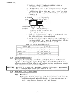
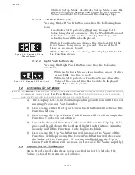
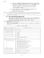
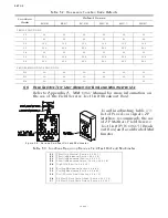
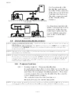
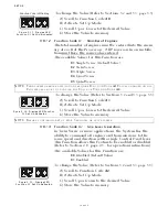
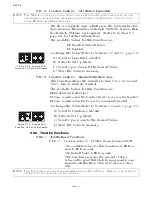
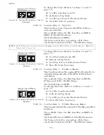
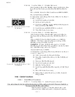
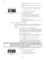
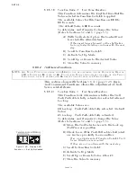
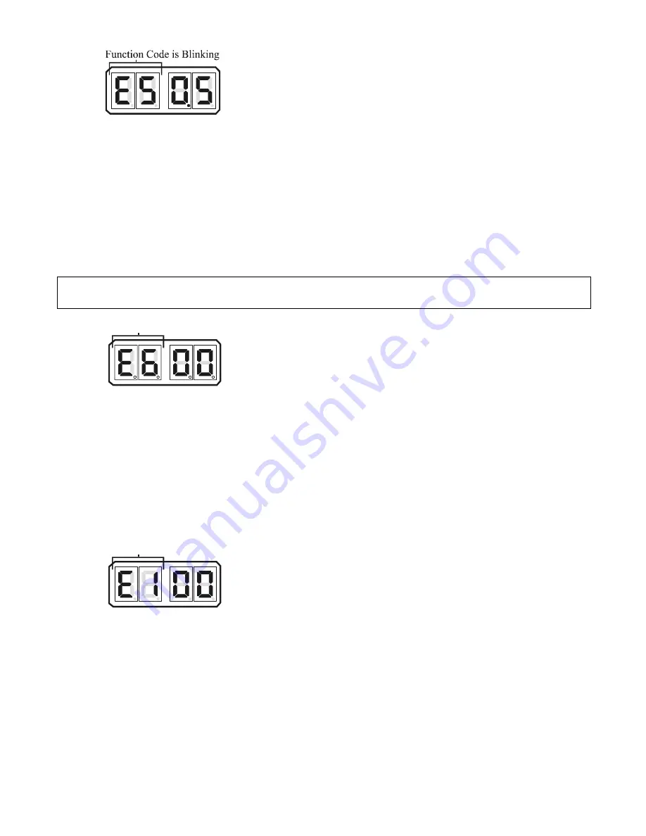
Figure 5-16: Display LED Function E5 Set Up
Activated
To change the Value (Refer to Sections 5-2 and 5-3,
page 5-5):
A) Scroll to Function Code E5.
B) Activate Set Up Mode.
C) Scroll Up or Down to the desired Value.
D) Store the Value to memory.
This Function Code Programs the RPM of the sec-
ond, elevated Idle.
The available Values for this Function are
00.0
to
20.0
% of Throttle Maximum.
The Default Value is
00.0
%.
The Value selected is a percentage of the Value
selected in Function Code
E3
– Throttle Maximum.
NOTE: T
HIS
F
UNCTION
IS
TYPICALLY
PROGRAMMED
DURING
D
OCK
T
RIALS
OR
S
EA
T
RIALS
. R
EFER
TO
S
ECTION
6-5,
PAGE
6-2.
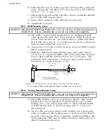
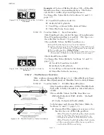
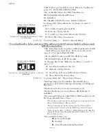
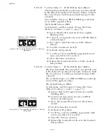
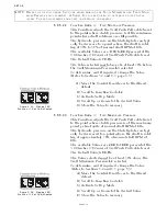
Figure 5-17: Display LED Function E6 Set Up
Activated
To change the Value (Refer to Sections 5-2 and 5-3,
page 5-5):
A) Scroll to Function Code
E6
.
B) Activate Set Up Mode.
C) Scroll Up or Down to the desired Value.
D) Store the Value to memory.
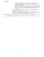
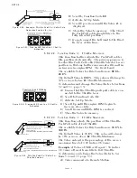
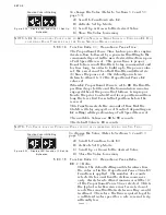
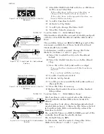
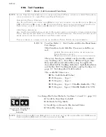
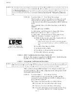
Figure 5-18: Display LED Function E1 Set Up
Activated
To change the Value (Refer to Sections 5-2 and 5-3,
page 5-5):
A) Scroll to Function Code
E1
.
B) Activate Set Up Mode.
C) Scroll Up or Down to the desired Value.
D) Store the Value to memory.
This Function limits the amount of Throttle permitted
in Astern.
The available Values for this Function are
00.0
% to
100.0
%.
The Default Value is
100.0
% of Throttle Maximum.
The Value selected is a percentage of the Value
selected in Function Code
E3
– Throttle Maximum.
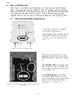
Function Code is Blinking
Function Code is Blinking
Содержание ClearCommand 9000 Series
Страница 1: ...ClearCommand 9000 Series Installation Operation and Troubleshooting Manual MM9000 I Rev C 2 5 08...
Страница 132: ......
Страница 133: ...APPENDIX A...
Страница 134: ......
Страница 139: ......
Страница 140: ...Page A 4...
Страница 143: ......
Страница 144: ...10...
Страница 148: ...Page A 18...
Страница 149: ...Page A 19 TEMPLATE...
Страница 150: ...Page A 20...
Страница 152: ...Page A 22...
Страница 154: ...Page A 24...
Страница 156: ...Page A 26...
Страница 157: ...Page A 27 Drawing 11488D 1 Twin Screw Single APS Connection Alternate Remote Switch...
Страница 158: ...Page A 28...
Страница 159: ...Page A 29 Drawing 11488D 2 Twin Screw Dual APS Connections...
Страница 160: ...Page A 30...
Страница 161: ...Page A 31 Drawing 11488D 3 APS Notes Page...
Страница 162: ...Page A 32...
Страница 164: ...Page A 34...
Страница 166: ...Page A 36...
Страница 170: ...Page A 40...
Страница 172: ...Page A 42...
Страница 176: ...Page A 46...
Страница 178: ...Page C 48 ZF Mathers LLC 12125 Harbour Reach Drive Suite B Mukilteo WA 98275...
Страница 179: ...APPENDIX B...
Страница 180: ......
Страница 234: ...Appendix B 6...
Страница 238: ...Appendix B 10...
Страница 242: ...Appendix B 14...
Страница 247: ...Service Field Test Unit Reference Manual MM13927 Rev E 4 07...
Страница 248: ......
Страница 250: ...Page ii Table of Contents...
Страница 264: ...SERVICE FIELD TEST UNIT MM13927 RvD 10 03 Page 3 2...
Страница 265: ...APPENDIX C...
Страница 266: ......
Страница 267: ...Appendix C 1 Drawing 12284A 1 ClearCommand Diagram all options...
Страница 268: ...Appendix C 2...
Страница 269: ...Appendix C 3 Drawing 12284A 2 ClearCommand Circuit Board Connections...
Страница 270: ...Appendix C 4...
Страница 271: ...Appendix C 5 Drawing 12284A 3 ClearCommand Drawing Notes Page...
Страница 272: ...Appendix C 6...

