TROUBLESHOOTING
Page B10-3
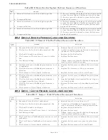
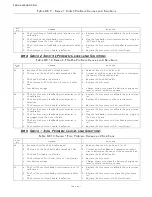
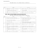
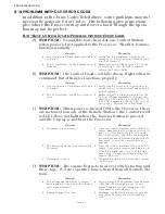
B10-4S
OLENOID
C
LUTCH
C
ONTROL
S
YSTEM
P
ROBLEMS
W
ITHOUT
E
RROR
C
ODES
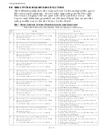
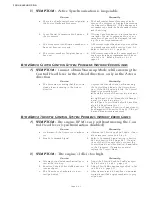
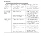
A) SYMPTOM:
Cannot obtain Warm-up Mode while moving the
Control Head lever in the Ahead direction, only in the Astern
direction.
B10-5E
LECTRONIC
T
HROTTLE
C
ONTROL
S
YSTEM
P
ROBLEMS
W
ITHOUT
E
RROR
C
ODES
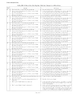
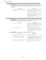
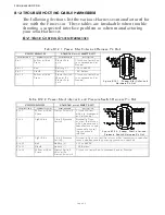
A)
SYMPTOM:
The engine RPM’s vary, without moving the Con-
trol Head lever (synchronization disabled).
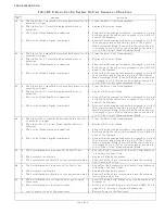
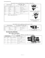
B)
SYMPTOM:
The engine’s Idle speed is too high.
Cause
Remedy
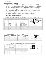
a. The Processor is sensing that the Control
Head’s lever is moving in the Astern
direction
Depress the Transfer Button while moving
the Control Head lever in the Astern direc-
tion. If the LED begins to blink, the Control
Head is incorrectly wired.
•
Check the colors of the wires at pins 5 and
7.
•
A right hand Control Head should have yel-
low at pin 5 and blue at pin 7.
•
A left hand Control Head should have blue
at pin 5 and yellow at pin 7.
•
Ahead and Astern Solenoid Wires need to
be reversed.
Cause
Remedy
a. Problem with the Governor.
a. Connect the Break-out Box (p/n 13927) as
shown in the Throttle Testing Section of the
Service Field Test Unit Manual. If variations
are seen, proceed to Step B). If no variations
are seen, contact a certified engine
mechanic.
b. Erratic Command Signal.
b. Refer to Command Signal testing in Section
and Section B5-1.2, page B5-2. If variations
of the A/D counts occur, connect the Control
Head to another Station (if available) on the
Processor. If variations persist, replace the
Control Head.
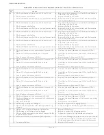
Cause
Remedy
a. Function Code
E2
Throttle Minimum is
incorrectly set.
a. Adjust Throttle Minimum as specified in Sec-
tion 5-6.2.3.2, page 5-20.
b. Function Code
E6
High Idle is pro-
grammed to a value other than
00.0
.
b. Decide whether High Idle is required or not.
If not required, set the value of
E6
to
00.0
. If
the High Idle feature is required, press the
Transfer Button for approximately 1/2 second
to toggle to Low Idle.
c. The Governor or its Control Module is
incorrectly adjusted or faulty.
c. After Causes a. and b. have been eliminated,
contact a certified engine mechanic to prop-
erly adjust.
Содержание ClearCommand 9000 Series
Страница 1: ...ClearCommand 9000 Series Installation Operation and Troubleshooting Manual MM9000 I Rev C 2 5 08...
Страница 132: ......
Страница 133: ...APPENDIX A...
Страница 134: ......
Страница 139: ......
Страница 140: ...Page A 4...
Страница 143: ......
Страница 144: ...10...
Страница 148: ...Page A 18...
Страница 149: ...Page A 19 TEMPLATE...
Страница 150: ...Page A 20...
Страница 152: ...Page A 22...
Страница 154: ...Page A 24...
Страница 156: ...Page A 26...
Страница 157: ...Page A 27 Drawing 11488D 1 Twin Screw Single APS Connection Alternate Remote Switch...
Страница 158: ...Page A 28...
Страница 159: ...Page A 29 Drawing 11488D 2 Twin Screw Dual APS Connections...
Страница 160: ...Page A 30...
Страница 161: ...Page A 31 Drawing 11488D 3 APS Notes Page...
Страница 162: ...Page A 32...
Страница 164: ...Page A 34...
Страница 166: ...Page A 36...
Страница 170: ...Page A 40...
Страница 172: ...Page A 42...
Страница 176: ...Page A 46...
Страница 178: ...Page C 48 ZF Mathers LLC 12125 Harbour Reach Drive Suite B Mukilteo WA 98275...
Страница 179: ...APPENDIX B...
Страница 180: ......
Страница 234: ...Appendix B 6...
Страница 238: ...Appendix B 10...
Страница 242: ...Appendix B 14...
Страница 247: ...Service Field Test Unit Reference Manual MM13927 Rev E 4 07...
Страница 248: ......
Страница 250: ...Page ii Table of Contents...
Страница 264: ...SERVICE FIELD TEST UNIT MM13927 RvD 10 03 Page 3 2...
Страница 265: ...APPENDIX C...
Страница 266: ......
Страница 267: ...Appendix C 1 Drawing 12284A 1 ClearCommand Diagram all options...
Страница 268: ...Appendix C 2...
Страница 269: ...Appendix C 3 Drawing 12284A 2 ClearCommand Circuit Board Connections...
Страница 270: ...Appendix C 4...
Страница 271: ...Appendix C 5 Drawing 12284A 3 ClearCommand Drawing Notes Page...
Страница 272: ...Appendix C 6...


