


DOCK TRIALS
Page6-1
6
DOCK TRIALS
6-1 C
ONTROL
H
EADS
(E
NGINES
S
TOPPED
)
A) Turn power ON to the Control System.
B) The Control Head at each Remote Station should produce an
intermittent tone.
C) Perform each of the following steps on all Remote Stations.
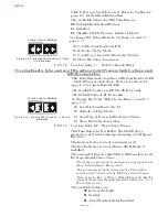
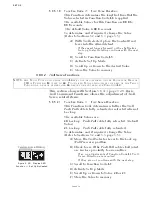
1. Move the Control Head’s lever(s) full Ahead and full Astern.
Ensure that there are no obstructions to the movement, the Pro-
cessor reacts to the lever movement, and that no tones are gener-
ated.
2. Place the Control Head’s lever(s) in the Neutral position.
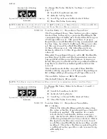
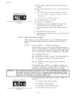
3. Depress and hold the Station transfer button while moving the
Control Head’s lever(s) to the Ahead detent. Release the transfer
button.
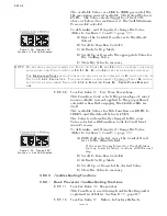
• The red LED on the Control Head should blink, indicating
Warm-up Mode has been entered. Warm-up Mode only oper-
ates in the Ahead direction.
6-2 S
TART
I
NTERLOCK
(E
NGINES
S
TOPPED
)
A) Turn the Processor DC power OFF.
• Verify that the engine(s) will not start.
B) Turn Processor DC power ON. Do not take command at a
Remote Station.
• Verify that the engine(s) will not start.
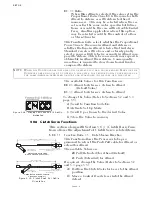
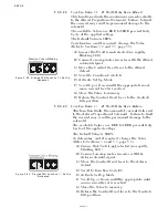
C) Take command at a Remote Station. Place the Control Head’s
lever(s) to approximately 50% of the throttle range.
• Verify that the engine(s) will not start.
D) Place the Control Head’s lever(s) in the Neutral/Idle position.
Take command at a Remote Station.
• Verify that the engine(s) will start in this position.
6-3 E
NGINE
S
TOP
S
WITCHES
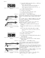
Start the engine(s) and verify that the Stop switches (normally
push buttons) function correctly at all Remote Stations.
WARNING: I
T
IS
IMPERATIVE
THAT
THE
INFORMATION
PROVIDED
IN
THE
PREVIOUS
S
ECTIONS
HAS
BEEN
READ
AND
FOLLOWED
PRECISELY
,
PRIOR
TO
ATTEMPTING
A
D
OCK
T
RIAL
.
CAUTION: With I/O or Outboard applications, do not attempt to shift into or out of
gear with engines stopped. This may cause a jam condition or damage to
the linkage to some clutch configurations.
NOTE: O
N
TWIN
SCREW
APPLICATIONS
,
THE
FOLLOWING
TESTS
MUST
BE
PERFORMED
ON
BOTH
SIDES
.
I
F
ANY
OF
THE
FOLLOWING
TESTS
FAIL
,
CONSULT
A
PPENDIX
B T
ROUBLESHOOTING
.
Содержание ClearCommand 9000 Series
Страница 1: ...ClearCommand 9000 Series Installation Operation and Troubleshooting Manual MM9000 I Rev C 2 5 08...
Страница 132: ......
Страница 133: ...APPENDIX A...
Страница 134: ......
Страница 139: ......
Страница 140: ...Page A 4...
Страница 143: ......
Страница 144: ...10...
Страница 148: ...Page A 18...
Страница 149: ...Page A 19 TEMPLATE...
Страница 150: ...Page A 20...
Страница 152: ...Page A 22...
Страница 154: ...Page A 24...
Страница 156: ...Page A 26...
Страница 157: ...Page A 27 Drawing 11488D 1 Twin Screw Single APS Connection Alternate Remote Switch...
Страница 158: ...Page A 28...
Страница 159: ...Page A 29 Drawing 11488D 2 Twin Screw Dual APS Connections...
Страница 160: ...Page A 30...
Страница 161: ...Page A 31 Drawing 11488D 3 APS Notes Page...
Страница 162: ...Page A 32...
Страница 164: ...Page A 34...
Страница 166: ...Page A 36...
Страница 170: ...Page A 40...
Страница 172: ...Page A 42...
Страница 176: ...Page A 46...
Страница 178: ...Page C 48 ZF Mathers LLC 12125 Harbour Reach Drive Suite B Mukilteo WA 98275...
Страница 179: ...APPENDIX B...
Страница 180: ......
Страница 234: ...Appendix B 6...
Страница 238: ...Appendix B 10...
Страница 242: ...Appendix B 14...
Страница 247: ...Service Field Test Unit Reference Manual MM13927 Rev E 4 07...
Страница 248: ......
Страница 250: ...Page ii Table of Contents...
Страница 264: ...SERVICE FIELD TEST UNIT MM13927 RvD 10 03 Page 3 2...
Страница 265: ...APPENDIX C...
Страница 266: ......
Страница 267: ...Appendix C 1 Drawing 12284A 1 ClearCommand Diagram all options...
Страница 268: ...Appendix C 2...
Страница 269: ...Appendix C 3 Drawing 12284A 2 ClearCommand Circuit Board Connections...
Страница 270: ...Appendix C 4...
Страница 271: ...Appendix C 5 Drawing 12284A 3 ClearCommand Drawing Notes Page...
Страница 272: ...Appendix C 6...