background image

97

CPSW Menu Structure

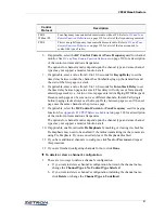
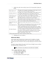
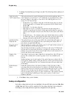
3. Configure the audio control settings as needed. The following table explains each 

setting:

4. Click 

Done

 when you are finished.

ANI Decode/Display

ANI (automatic number identification) is normally used for identification of mobile 
radios. ANI uses remote signaling tones that are either automatically or manually sent 
when the radio is keyed. One use for ANI is as a single-button-press on the radio to call for 
help.

On systems equipped with the ANI option, the ANI Decode / Display function will allow 
the ANI mode and the ANI address to be set.

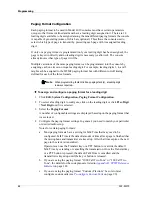
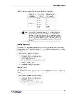
To configure ANI Decode / Display

1. Click 

Edit, Position Configuration

.

2. Click 

ANI Decode / Display

.

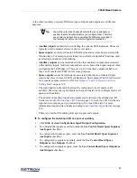
The ANI Configuration dialog window opens.

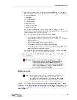
Muted Audio Level *

This number (0 to 99) represents the percentage of total volume to be used 
as a muted audio level for all channels of the position.

Minimum Audio Level *

This number (0 to 99) represents the percentage of total volume to be used 
as a minimum adjustable audio level for all channels of the position.

Default Volume Level *

This number (0 to 99) represents the percentage of total volume to be used 
as a power-up default volume level for all channels of the position.

Speaker Mute while 
Transmitting

When enabled, both select and unselect speakers will mute when you are 
transmitting. Disable if you want speakers to remain unmuted.

Mute all Idle Channels

When enabled, audio from channels that do not have “call” activity are 
muted. This is useful for a position that has many channels, since quiescent 
line noise will accumulate on the unselected speaker audio.

Unmute Idle Chan Upon 
Monitor

When enabled, channels unmute when the CTCSS monitor function is 
active.

Muting Signaling Tones

When enabled, tone remote signaling tones from the auxiliary audio input 
are muted at this position. Disable to hear the signaling tones.

Mic Delay Eliminator

The Mic Delay Eliminator puts a delay in the microphone voice signal so 
that the operator’s voice reaches the transmitting radio at the same time that 
the carrier is activated. Enable this to prevent the lost first syllables that can 
occur when transmitting over transmitter links or tone-remote control.
This function is typically disabled by default. Enable this for use with the 
Tone Remote System Adapter with Audio Delay, as described in the 
adapter’s technical sheet (P/N 011-0347).

* The percentage entered will be rounded to the nearest multiple of three.

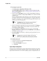
Note

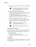
ANI decode is only possible from channels that have ANI enabled.

Содержание 4010

Страница 1: ...Model 4010 Radio Dispatch Console Installation and Programming 025 9227S ...

Страница 2: ...eriod of any defect If the defect is not the result of improper or excessive use or improper service maintenance or installation and if the Zetron Products or Zetron Accessories have not been otherwise damaged or modified after shipment AS ZETRON S SOLE AND EXCLUSIVE LIABILITY AND BUYER S SOLE AND EXCLUSIVE REMEDY Zetron shall either replace or repair the defective parts replace the Zetron Product...

Страница 3: ...ct with areas subject to high voltage or amperage Because some components can store dangerous charges even after power is disconnected always discharge components before touching Never insert objects of any kind through openings in the equipment Conductive foreign objects could produce a short circuit that could cause fire electrical shock or equipment damage Remove rings watches and other metalli...

Страница 4: ...Channel Card Jumpers and Switches on page 27 Corrected the channels associated with J2 J3 and J4 in Model 4010 Main Control Board on page 104 Added to the description of Instant Call on page 127 Updated JP6 B description in Configuration on page 51 Removed Entering IDs in Ericsson GE MDX Radio ...

Страница 5: ... Sequence 15 Console Installation 17 Overview 17 Important Notes 18 New Units 18 Program Run Switch 18 Physical Installation 18 Console Location 18 Console Access 18 Power 19 Primary Power 19 Auxiliary Power 19 System Grounding 20 Slot Mapping 21 Configuring Dispatch Consoles 24 Model 4010 Options 25 Configuring Dual Channel Cards 26 Channel Type 26 Line Termination 28 Busy Transmit Inhibit 28 Cha...

Страница 6: ...41 Level Adjustments 42 Receive Audio Adjustment 42 Microphone Adjustments 43 Auxiliary Audio Input Adjustment 44 Speaker Minimum Audio Level 44 Tone Level Adjustments 45 Transmit Audio Adjustment 45 Option Installation 47 Gooseneck Microphone 48 Desk Microphone 49 Footswitch 50 Headset Jackbox 50 Secondary Headset Jack Box 50 Introduction 50 Installation 51 Telephone Radio Headset Interface 53 Ov...

Страница 7: ...ettings 68 Model 4010 Parallel Status Option 69 Cable Installation 69 Channel Card Termination 69 Console Programming 70 GE Star Decoder 72 GE STAR Overview 72 GE STAR Decoder Setup 72 Error Indications 73 Output Format 73 Model 4010 T2 2R Base Station Installation 75 Method 1 75 Method 2 75 PTT Handset with Cradle 77 Programming 79 Introduction 79 Versions and Compatibility 79 DOS and Windows 79 ...

Страница 8: ...apter 107 Appendix B CPSW Reference Material 109 DC and Tone Remote Function Definitions 110 Achieving Motorola GE DC Control Currents 111 Paging Format Specifications 112 Description of Key Functions and Parameters 119 Channel Functions 119 System Functions 123 Auxiliary Input Output 128 Appendix C Maintenance 131 Battery Check Replacement 131 Firmware Upgrade 131 Display Board Adjustment 132 App...

Страница 9: ...s public service applications such as utility and industrial communications The Model 4010 may be tailored to fit the size of the system from 2 to 12 radio channels by adding dual channel cards as required The channels can be configured to support a mix of control types DC remote tone remote local control and E M control Figure 1 Model 4010 The diagram in Figure 2 illustrates a Model 4010 Radio Di...

Страница 10: ...el 4010 is a desktop console the Model 4010R is a rackmount console designed to be mounted into a rack or furniture with a built in rack mount compatible system In this manual both the Model 4010 and 4010R are referred to as the Model 4010 unless specifically stated otherwise RADIO D RADIO C RADIO B RADIO A Model 4010 Radio Dispatch Console Telephone Style 25 Pair Cable 10 Feet Long Channel Punch ...

Страница 11: ... Model 4010 This manual describes the installation of the Model 4010 Below is a list of the manuals and a description of their contents Manual Title Part Number Description Operator Manual 025 9226 Presents an overview of the console panels a description of the functions of each button and a detailed description of the Model 4010 Installation and Programming Manual 025 9227 Presents a description ...

Страница 12: ...uses 3 dB output increase Input Impedance 600Ω or 10KΩ 4 wire 3500Ω 2 wire Line Balance 66 dB at 1000 Hz Rx Sensitivity 30 dBm max at knee of compression adjustable Freq Response 3 to 1 dB from 250 5000 Hz except GT notch Compression Input level increase of 30 dB above the knee of compression causes 3 dB output increase Distortion 2 Call Light Sensitivity 20 dB below knee of compression Audio Outp...

Страница 13: ... Tone or DC Control detection LOTL optional Recorder Outputs 1 per channel TX RX audio summation plus 1 output per console various combinations of select unselect and microphone audio 0 dBm level 600Ω single ended outputs Capacity 12 radio channels plus 1 or 2 phone lines with an optional phone patch card Operating Temp 5 to 50 Celsius Voltage 13 5 VDC 11 5 VDC minimum 16 0 VDC maximum Current 2 5...

Страница 14: ... to be programmed to send one or an entire sequence of pages Each channel can be optioned to support a mix of control types DC remote tone remote local control and E M control The DC remote control requires one optional DC Control Daughter Board per DC channel This DC Control Daughter Board also has a line operated transmit light LOTL to show if a channel is in use via another source The tone remo...

Страница 15: ...quired per four channels Mapping Card slot mapping allocates a particular channel and console card slot to your base stations It also creates a cross reference between the channel and position names that you are familiar with After the card slots have been mapped the channel and console should be configured using their various jumpers and switches Wiring After the system has been configured then w...

Страница 16: ...tial operation the system will operate according to the programming done at the Zetron factory If you wish to alter operation through programming see Programming on page 79 Changes in the programming may be performed by you once the system is installed ...

Страница 17: ...ed option if ordered later Instructions for installing options are included in the following chapter Option Installation on page 47 Major sections in this chapter Important Notes on page 18 Physical Installation on page 18 Power on page 19 System Grounding on page 20 Slot Mapping on page 21 Configuring Dispatch Consoles on page 24 Configuring Dual Channel Cards on page 26 Wiring to the Channels on...

Страница 18: ...g the options in the 4010 On a desktop Model 4010 this switch is located on the bottom of the unit The normal or run switch position is to the right towards the Unselect speaker Detailed programming instructions are provided in Programming on page 79 Physical Installation Console Location When preparing to place the control panels consider the amount of tabletop space required not only for the con...

Страница 19: ... is labeled F1 on the Control Board near the input power connect J5 The fuse is accessible by lifting the top cover of the unit If replacement is required replace only with 2 5 ampere slow blow AGC type fuse Auxiliary Power A connection for auxiliary power is also provided internal to the unit Screw terminal connector J16 is used to connect 12 VDC and ground The specifications for the auxiliary DC...

Страница 20: ... gauge copper conductor or equivalent braided strap bus bar must be connected between the ground lug of each block and the earth ground or central star grounding point With the protected punch down blocks it is best to wire directly to the earth ground if possible Each piece of equipment should have its chassis grounded to the central star point with a separate ground wire The gauge of the wire de...

Страница 21: ...uested factory programming since the map is required before the system can be programmed If prepared at the factory you will find a copy of your slot map with this manual Even if the slot map has been provided you are encouraged to continue to read this section The first step in preparing your slot map is to become familiar with the channel cards and option boards contained in the console Open the...

Страница 22: ...d the channel cards already plugged into the assigned slots Slots J12 J7 are for channel cards or Auxiliary I O boards J6 is for the Phone Patch card On the back of the unit are three 50 conductor male Amphenol type plugs used to connect the Console to the punch down blocks and radios These are designated J4 channels 1 4 J3 channels 5 8 and J2 channels 9 12 Figure 6 A Model 4010 with its case open...

Страница 23: ...ard channels 1 2 Aux I O Card J11 Dual Channel Card channels 3 4 Aux I O Card J10 Dual Channel Card channels 5 6 Aux I O Card J9 Dual Channel Card channels 7 8 Aux I O Card J8 Dual Channel Card channels 9 10 Aux I O Card J7 Dual Channel Card channels 11 12 Aux I O Card J6 Phone Patch Card line 1 2 ...

Страница 24: ...set JP4 Headset Handset Unselect Monitor Occasionally it is desirable to monitor both Select and Unselect audio on the earpiece of the headset or handset Jumper JP4 may be used to enable the Unselect audio monitoring A Unselect audio not heard at headset handset B Unselect audio heard at headset handset JP5 Auxiliary Audio input impedance If an external encoder is used use JP5 to set the input imp...

Страница 25: ...y may be different than the typical positions listed here Note On the Model 4010 the program position is toward the Select speaker Option Code Description Default B DC I Boost enabled For DC channels only this provides an initially boosted current to overcome greater capacitance found in longer wire runs After the initial boost current returns to normal levels DC I Boost disabled Normal current le...

Страница 26: ... Each channel in the Model 4010 can be programmed to be one of three control types Local Tone or DC This programming is performed using CPSW software Refer to Channel Configuration on page 85 for details In addition to programming there are some jumper and switch settings that must be reviewed Local Control This is the default for all channels and no additional hardware is required If a Tone Remot...

Страница 27: ...s following Table 4 describe the jumper switch option settings Table 4 Dual Channel Card Jumpers and Switches Caution The cards in a Model 4010 are not hot swappable in the unit You must power the unit off before any cards can be safely removed or added to the system Caution When comparing the DIP switch s ON OFF labelling with the Model 4010 s ON OFF labelling the installer might notice that the ...

Страница 28: ... transmission on a Busy channel A channel is Busy whenever its cross busy input Busy In is activated by a locally paralleled control point or when its line operated transmit light LOTL is activated by a remotely paralleled control point Usually inhibiting while busy is desired to prevent confused communications and to keep proper line terminations and levels However when line conditions cause fals...

Страница 29: ... installed the OPT switch controls the current setting level for transmission In the OFF position the standard Zetron level which is appropriate for most applications is used In the ON position the standard Motorola GE settings are used Full Duplex Each channel may be configured for full duplex or simplex operation Full duplex operation requires a 4 wire system and allows the dispatcher to transmi...

Страница 30: ...is programmable via CPSW allowing the CALL indicator to remain on for a number of seconds after the actual voice activity ends The hang time for patching is controlled by the channel or telephone card VOX circuit Experience has shown that an optimal patch hang time is about one second which is the factory default Contact Technical Support if you need to change this timing ...

Страница 31: ...A channel B channel C and channel D Each channel has 12 signals brought out on these plugs These signals are the same regardless of the method of control used by the Dual Channel Card The following subsections describe the channel signals Push to Talk The dry contacts across these two signals close whenever the channel is transmitting This may be used for single function local transmitter keying o...

Страница 32: ...ltages up to 1500 VAC The 4 wire receive sensitivity may be adjusted to 30 dBm using the 4W RX adjustment on the channel card edge Cross Busy Input Output This input output pair is used for cross busy handshaking for multiple parallel control point arbitration The X Busy Output sinks current to ground when the channel is being transmitted upon The X Busy Input inhibits transmission on the channel ...

Страница 33: ...or Console I O Table 7 summarizes the signals found on each channel plug The table also contains the wire colors for the 25 pair cables often used to connect to the plugs 2 2uF 600 Ohm 600 Ohm 10K Ohm 2 2 uF 10K Ohm 3 3K Ohm 10K Ohm 12V 12V 600 Ohm 10 uF 50 Pin Connector Pin Numbers J2 J3 and J4 Ch A Ch B Ch C Ch D Signal 1 7 13 19 PTT 26 32 38 44 PTT 2 8 14 20 Record 27 33 39 45 Analog Ground 3 9...

Страница 34: ...11 Blue Black Chan B Rx Chan B X Busy Out Black Org 37 12 Org Black Chan B X Busy In Chan C PTT Black Green 38 13 Green Black Chan C PTT Analog Ground Black Brown 39 14 Brown Black Chan C Recorder Out Digital Ground Black Slate 40 15 Slate Black Chan C Aux Output Chan C TX Yellow Blue 41 16 Blue Yellow Chan C TX Chan C Rx Yellow Orange 42 17 Orange Yellow Chan C Rx Chan C X Busy Out Yellow Green 4...

Страница 35: ... J J 10 Chan B RX 36 J J 36 Chan B RX 11 J J 11 Chan B X Busy Out 37 J J 37 Chan B X Busy In 12 J J 12 Chan C PTT 38 J J 38 Chan C PTT 13 J J 13 Analog GND 39 J J 39 Chan C Record 14 J J 14 Ground 40 J J 40 Chan C Aux Output 15 J J 15 Chan C TX 41 J J 41 Chan C TX 16 J J 16 Chan C RX 42 J J 42 Chan C RX 17 J J 17 Chan C X Busy Out 43 J J 43 Chan C X Busy In 18 J J 18 Chan D PTT 44 J J 44 Chan D PT...

Страница 36: ...an A PTT Analog Gnd Chan A Record Ground Chan A Aux Output Chan A Tx Chan A Tx Chan A Rx Chan A Rx Chan A X Busy Out Chan A X Busy In Chan B PTT Chan B PTT Analog Gnd Chan B Record V Chan B Aux Output Chan B Tx Chan B Tx Chan B Rx Chan B Rx Chan B X Busy Out Chan B X Busy In Chan C PTT Chan C PTT Analog Gnd Chan C Record Ground Chan C Aux Output Chan C Tx Chan C Tx Chan C Rx Chan C Rx Chan C X Bus...

Страница 37: ...y I O Cards see Model 4010 Auxiliary I O Card on page 56 Each Auxiliary I O Card adds six auxiliary inputs and six auxiliary outputs There is no method for adding spare inputs or spare outputs Inputs The Console has eight inputs which are a standard feature and located on the Control Board as are the outputs below Inputs are programmed through CPSW see Input Output Configuration on page 90 Inputs ...

Страница 38: ... and normally open NO contacts brought out to connector P7 These contacts are capable of 1 Amp and 50 V non inductive load Wiring access is through the rear of the unit The mating connector is provided with the unit The connector pinout is listed in Table 9 Table 9 P7 Outputs Output 1 has a special function that can be used to generate an off hook signal for the TRHI see Telephone Radio Headset In...

Страница 39: ...key top from its plastic plunger Grasp the key top with thumb and forefinger placed on horizontal edges of the key Gently pull the key top off Pliers may be used but care must be taken so not to slip and scratch the cover Only the outer portion of the key should be grasped when removing to allow the lower locking rib to release Use a rocking motion to release one side at a time Labels may be made ...

Страница 40: ...anel via the loop cable from the Model 4010 Each panel is also protected by a fuse labeled F2 which is accessible via the cutout in the rear panel It should be replaced only with a 2 0 ampere AGC type fuse Loop Address Because two expansion panels may be included in the data loop of the console each of these units must have a unique loop address to identify it from another identical unit Jumper JP...

Страница 41: ... the number of DC channels found c the number of Aux I O channels found e the number of phone channels found i the number of ANI channels found The card status display represents the actual physical cards detected by the firmware and not necessarily the configuration programmed by CPSW although they should agree for proper console operation If the display shows PROGRAM instead of the console syste...

Страница 42: ...e been completed Also levels are best adjusted when the system is connected to the intended radio base stations Table 11 Level Adjustment Locations Receive Audio Adjustment The receive audio on the Dual Channel Card should be adjusted first Each channel has the adjustments labeled on the back of the console While a 1000 Hz tone with audio level 12dBm 193 mV AC RMS is being applied to the channel r...

Страница 43: ...ise to be amplified when the operator is not speaking Proper adjustment and microphone practices will eliminate background noise from the transmitted audio The microphone levels are adjusted by speaking into the console microphone while transmitting at a normal voice level and distance from the microphone and turning the adjustment until the background noise level is removed without reducing the a...

Страница 44: ...d audio from the console will be at 0 75 Vrms 0 dBm 2 2 VPP Speaker Minimum Audio Level The Select and Unselect Speakers have adjustments to set the minimum audio level that the front panel volume knobs may reduce the level to These are set at the factory for no audio output completely counterclockwise with the volume knobs completely off The minimum level can be set with the vertical mounted pote...

Страница 45: ... level and may be set as desired Paging alert and warning tones may be monitored on the Unselect or Select Speakers as determined by JP10 The level of the monitor signal may be adjusted with R104 Transmit Audio Adjustment Adjust the transmit audio on the Dual Channel Card after other audio adjustments have been made The TXA or TXB test points do not reflect the actual transmitted level and line lo...

Страница 46: ...Console Installation 46 025 9227S ...

Страница 47: ...phone Radio Headset Interface on page 53 Model 4010 Phone Patch Card on page 54 Model 4010 Auxiliary I O Card on page 56 Model 4010 Tone Remote System Adapter on page 62 Model 4010 DC Remote Daughter Board on page 64 Model 4010 Tone LOTL Daughter Board on page 66 Model 4010 Channel ANI Decoder on page 67 Model 4010 Parallel Status Option on page 69 GE Star Decoder on page 72 Model 4010 T2 2R Base ...

Страница 48: ...the microphone adapter with the two threaded studs The cable is connected to P12 on the Control Board near the microphone adapter mounting position Pin 1 of the cable is the white wire and is connected to the P12 Pin 1 which is nearest the rear of the console The system configuration normally uses the gooseneck microphone as the default audio source If the audio source has been changed e g to a de...

Страница 49: ...the desk microphone as the audio source use the Miscellaneous menu in CPSW to modify the system configuration Edit Position Configuration Miscellaneous Signal Rigid Desktop Microphone Flexible Desktop Microphone Aux Audio Connector Ground Shield Green Pin 6 Audio Yellow Blue Pin 7 Audio Bare wire White Blue Pin 8 PTT Red White Brown Pin 9 PTT Bare wire Brown Pin 10 Mon Black White Orange Pin 11 Mo...

Страница 50: ...h on the side of the Headset Jackbox to configure it The jack box 9 pin cable is plugged into the J1 headset connector on the back of the console or in the Expansion port J1 on the Secondary Headset Jackbox For additional instructions refer to S4000 Headset Jackbox Installation Instructions P N 011 0540 Secondary Headset Jack Box Introduction The Zetron Series 4000 Secondary Headset Jack Box SHJB ...

Страница 51: ...ttings PTT override operation may be used if each secondary headset jack box is provided with its own transmit switch such as a foot switch or 6 wire PTT headset When PTT override is enabled JP1 JP3 and JP6 set to position B pressing PTT on the primary jack box mutes the secondary jack box transmit audio and routes the primary jack box audio to the transmitter allowing the primary jack box user to...

Страница 52: ...to the console Wiring to Additional Jack Boxes If more than one jack box is to be installed for a single console only one Secondary Headset Jack Box connects to the console All additional jack boxes must connect in daisy chain fashion to the initial jack box at connector J1 expansion at the rear of the box If either the standard headset jack box P N 950 9327 or the Telephone Radio Headset Interfac...

Страница 53: ... types of telephone instruments do not provide an OFF HOOK contact This is especially true of systems controlled by an Automatic Call Distributor ACD or systems that use newer electronic telephones In these cases check with the phone or headset manufacturer to see if a modification can be made to provide an OFF HOOK signal If no OFF HOOK signal is available from the telephone instrument the TRHI c...

Страница 54: ...the back of the console and lifting the top open The card is inserted in the last slot J6 which has the cutouts in the back panel made to fit Insert the side away from the back panel in first then rock the card towards the back panel into position Take care that the LED is properly positioned Secure the board by inserting the screw through the hole in the back panel into the bracket on the card Th...

Страница 55: ...ment the Phone Patch card should be attached to its intended phone line Dial a phone number that can be answered and silenced no automated messages or loud background noises Transmit a 1000 Hz tone to the phone channel via the console The Alert 1 key is normally programmed at the factory for a continuous 1 kHz tone While monitoring the level at the receive audio test point alternately adjust poten...

Страница 56: ...back panel in first and then rock the card towards the back panel into position Secure the board by inserting the screw through the hole in the back panel into the bracket on the I O board Auxiliary Outputs The outputs are the common and normally open contacts of a relay whose contacts are rated at 1 A 50 VDC Each output has two jumpers associated with it One jumper will change the normally open o...

Страница 57: ...r than the 5 V interface level Auxiliary Output Jumper Settings Each relay output has two sets of jumpers as shown in Figure 9 Figure 9 Auxiliary Output Relay Jumpers By arranging these jumpers each relay output can be used as described in Table 15 Output Jumpers Output 1 JP1 and JP7 Output 2 JP4 and JP10 Output 3 JP6 and JP12 Output 4 JP2 and JP8 Output 5 JP3 and JP9 Output 6 JP5 and JP11 Typical...

Страница 58: ... second Auxiliary I O Board will be assigned values 15 20 and any additional boards will follow in groups of six For example Input 1 on the first Auxiliary I O Board will be Input 9 to CPSW and Input 2 will become Input 10 to CPSW This sequence is followed for output signal numbering also Table 16 I O Numbers vs CPSW Numerical Assignment Relay Contact Configuration Jumper Pair JPY Jumper Pair JPX ...

Страница 59: ...el Assignment vs Connector Pinout Table 18 Signal vs Pin Assignment Upper Half Note The locations of the Auxiliary I O Boards are sensed during power up and are assigned the proper sequence If an Auxiliary I O Board is added to a channel slot before an existing board the I O assignment of the existing board will have to be changed via CPSW to match the new I O numbers assigned to it by the Model 4...

Страница 60: ...t Lower Half Signal Pin Pin Signal open 38 13 Input 1 Analog GND 39 14 Input 2 Ground 40 15 Input 3 open 41 16 Input 4 RLY1B 42 17 RLY1A RLY2B 43 18 RLY2A RLY3B 44 19 RLY3A Ground 45 20 Input 5 open 46 21 Input 6 RLY4B 47 22 RLY4A RLY5B 48 23 RLY5A RLY6B 49 24 RLY6A ...

Страница 61: ...EN 34 J J 34 INPUT 6 9 J J 9 RLY 4B 35 J J 35 RLY 4A 10 J J 10 RLY 5B 36 J J 36 RLY 5A 11 J J 11 RLY 6B 37 J J 37 RLY 6A 12 J J 12 OPEN 38 J J 38 INPUT 1 13 J J 13 ANALOG GND 39 J J 39 INPUT 2 14 J J 14 GROUND 40 J J 40 INPUT 3 15 J J 15 OPEN 41 J J 41 INPUT 4 16 J J 16 RLY 1B 42 J J 42 RLY 1A 17 J J 17 Lower half for RLY 2B 43 J J 43 Slot 2 J 11 RLY 2A 18 J J 18 Slot 4 J 9 RLY 3B 44 J J 44 Slot 6...

Страница 62: ...r board lines up with the mounting hole in the back panel Secure the board by inserting the screw through the back panel hole into the bracket Adjustments The Tone Remote System Adapter comes from the factory adjusted for the nominal level required by most transmitters The guard tone level is set by the potentiometer that is labeled GT To maintain the proper signal level between the guard tone and...

Страница 63: ...h Filter Jumpers on the Tone Remote Board The notch filtering only applies to incoming audio Although the output does not notch any guard tone frequencies that may be present a third party notch filter can be used Audio Delay The Tone Remote with Audio Delay Board 950 9922 has an additional feature which allows for audio delay in both the Patch Bus and the MIC Bus for up to a maximum of 1 0 second...

Страница 64: ...e DC Remote Daughter Board P N 702 9380 is an option board that is installed on the Dual Channel Board This option will allow the channel card to generate the DC current required to control DC remote controlled transmitters Normally this option is installed at the factory but it can also be installed in the field with the following instructions Installation The cover of the Model 4010 must be rais...

Страница 65: ...pot R15 is accessible from the top of the unit with Model 4010 cover open and with a current meter in series with the transmission line can be adjusted to the desired level The factory adjustment is for 0 5 milliampere programmable steps Programming The Console Programming System CPSW is used to set the current levels for the various transmission requirements The DC board can be programmed in 0 5 ...

Страница 66: ...comes with two standoffs and mounting screws First remove the screws and then install the Daughter board into the strip connector Using the screws and standoffs secure the board to the Dual Channel Card Insert the Dual Channel Card into the channel slot by placing the side away from the back panel in first then rock the card towards the back panel into position Take care that the LEDs are properly...

Страница 67: ...the screws and standoffs secure the board to the Dual Channel Card Insert the Dual Channel Card into the channel slot by placing the side away from the back panel in first then rock the card towards the back panel into position Take care that the LEDs are properly positioned Secure the board by inserting the screw through the hole in the back panel into the bracket on the card Checkout After the c...

Страница 68: ...re used for 5 6 tone decoding only The standard setting is both jumpers in position B FSK Tone Decoder Jumper and Switch JP3 shorts out the incoming audio stream disabling the ANI decode This would normally be left open The SW1 4 position bitswitch is not used Note The Model 4010 is able to decode only the unit identification in a PTT ID ANIs that are configured with fleet or group designation sep...

Страница 69: ...ect PTT PTT Tx Tx Rx and Rx if 4 wire of the two channels The Busy Out signal must be connected to the Busy In of the associated channel of the second console and the Busy In to the associated Busy Out See Figure 10 for the split 50 block configuration The parallel status cable P N 709 7313 is installed between the two consoles Data Comb connectors 6 pin RJ 11 This cable transfers the frequency in...

Страница 70: ...he console must be programmed using the Console Programming System CPSW to enable the Parallel Status option If the console is ordered with the Parallel Status option it is programmed at Zetron Refer to Miscellaneous on page 99 for programming information ...

Страница 71: ... RX Chan B RX 11 J J 11 Chan B RX Chan B X Busy Out 37 J J 37 Chan B X Busy Out Chan B X Busy In 12 J J 12 Chan B X Busy In Chan C PTT 38 J J 38 Chan C PTT Chan C PTT 13 J J 13 Chan C PTT Analog GND 39 J J 39 Analog GND Chan C Record 14 J J 14 Chan C Record Ground 40 J J 40 Ground Chan C Aux Output 15 J J 15 Chan C Aux Output Chan C TX 41 J J 41 Chan C TX Chan C TX 16 J J 16 Chan C TX Chan C RX 42...

Страница 72: ...o 1 or 1 to 0 The format of the data is shown below Word 1 11 10 9 8 7 6 5 4 3 2 1 Sync Bits ID Bits Word 2 T1 T2 S1 S2 S3 S4 M1 M2 M3 M4 Tag Status Message Error Bits Bits Bits Detection Bits Typically the GE STAR information is transmitted in a short burst of three repeated messages of the above format preceded by a 16 bit preamble of alternating l s and 0 s The repetitions and error detection o...

Страница 73: ...le as a sequence of characters and numbers that represent the decoded GE STAR ID The displayed ID starts with either a number sign for non emergency ID s or a star for emergency IDs followed by the four digit ID number 0000 9999 followed by a status or message character if present in the transmission The possible outputs are shown below Switches 4321 Description Extra ID Bits 0110 12 bit Mobile Po...

Страница 74: ...Request to Talk ID xxxxC Stuck Mic ID xxxx PTI ID xxxx Emergency ID xxxxD Man Down ID where xxxx decoded GE STAR ID 0000 2047 w 11 bit decoding 0000 4095 w 12 bit decoding 0000 8191 w 13 bit decoding 0000 9999 w 14 bit decoding Output Description xxxx S Mobile Decode S Status if any xxxx S Portable Decode S Status if any Output Description xxxx S Decoded for system 0 1 2 or 3 only S Status if any ...

Страница 75: ...m the channel as a T2 2R channel In addition to a channel select button include a F1 F2 button sent at Xmit for transmit frequency selection and optionally an R2 On Off button for second receiver muting at the base station If Instant Select is desired use an F1 select and an F2 select button instead of the conventional select button Method 2 This method allocates two system channels to the T2 2R b...

Страница 76: ...st Frequency Receiver Second Frequency Receiver 2 Wire TX RX Channel B F2 RX 4 Wire RX see note Busy Output Busy Mute Input Busy Output Busy Mute Input 2 Wire TX RX Channel A F1 RX 4 Wire RX No Connection Channel B Configuration 2 wire termination low impedance Configuration switch 2 x mute On Channel A Configuration 2 wire termination high impedance Configuration switch 6 x mute On Base Station D...

Страница 77: ...y 2 PLCS 6 7 TO P3 10 PLCS 2 1 8 5 4 INSTALL PINS AND HOUSING ON OTHER END OF WIRES EACH WIRE TO HOOKSWITCH TERMINALS AS SHOWN 1 CUT WIRE INTO 2 6 PIECES SOLDER ONE END OF 11 NOTES ITEM QTY PART NUMBER DESCRIPTION 1 2 220 0200 SCREW 6 32x1 PAN PHL S Zn 4 2 234 0017 WASHER STAR 8 CTSK SS 3 2 234 0011 WASHER LOCK SPLIT 4 S Zn 7 1 401 0083 CONN CRIMP TERM HOUSING 2 POS 6 2 401 0082 CRIMP TERM 5 2 251...

Страница 78: ...Option Installation 78 025 9227S ...

Страница 79: ...support the Model 4010 or the Model 4116B and 4018 4118 This chapter provides instruction for CPSW for the Model 4010 only The following table can help you identify the correct documentation for your model Versions and Compatibility DOS and Windows CPSW replaces CPS an older program with similar functionality but created for use in MS DOS The older CPS application may be used within a command line...

Страница 80: ...er Installation Installation To install CPSW follow the instructions provided with it CPSW Installation Notes P N 011 0795 Uninstallation To uninstall CPSW CPSW uses the standard Windows procedure for uninstallation 1 From the Windows Control Panel double click Add Remove Programs 2 In the alphabetical list of installed programs find and click Zetron CPSW to select it 3 With Zetron CPSW selected c...

Страница 81: ...t Select Key Display Mode Received Call Light Duration Dynamic Mic Electret Mic Spare Input 9 Hookswitch Steers Display Operation Dashes 12 Hour Time 24 Hour Time Position Layout Panel 2 ANI Decode Display Operating Mode Unmute Channel Upon Receiving ANI Communication Help Recieve config from Position Set Serial Port Send config to Position Contents and Index About CPSW Open Save New Exit Save As ...

Страница 82: ... Call Tx unselected channels Monitor Site Intercom Burst Tone Select Wild Card II On Off CTCSS Select Repeat On Off Coded Clear Second Receiver Unmute Mute Wild Card I On Off DC TONE Spare Output Momentary Spare Output Toggle Spare Output Latching Volume Adjust Mute Adjust Volume Up Volume Down Volume Mute Custom Channel Functions Volume Reset Group Select Channel Test Clock Set Diagnostics Reset ...

Страница 83: ... step by step procedures to cover everything you need to do in order to configure your consoles Starting CPSW Start CPSW by double clicking on its shortcut Alternatively the program itself is located in C Program Files Zetron CPSW and titled CPSW_Application exe assuming the default location was used during installation If you don t use the shortcut CPSW will prompt you for the system type which i...

Страница 84: ... the bottom of the Model 4010 used to switch the console between RUN and PROGRAM modes Move the switch to the program position which is towards the gooseneck MIC and away from the DATA IN DATA OUT and COMB jacks The console display shows PROGRAM 3 In CPSW click Communication Receive config from Position 4 Click OK to begin receiving the configuration The console display shows UpLoading CPS while i...

Страница 85: ...l types paging formats and I O System Settings Channel Configuration To configure channels 1 Click Edit System Configuration Channel Configuration 2 Select the channel number to configure using the up and down arrows next to Channel Number 3 Enter a Channel Name Channel Name is used for reference only and can be left blank if desired Note CPSW configuration files ending in cf1 are used for M4010 a...

Страница 86: ...the channel type you have configured some of the following settings may not be relevant and available for configuration Note Channels 13 and 14 are only supported by the Phone Patch Interface Card Therefore the only compatible channel type for those channels is Telephone Control Control Protocol Description T1R1 Without Paging Single frequency standard tone controlled radio without paging option T...

Страница 87: ...age 109 for a description of the control currents and tone frequencies The options for channel monitor depend upon the channel type and some channel types may not support a monitor function at all 10 If applicable enable or disable De Emphasis by marking or clearing its checkbox De Emphasis may need to be enabled if the radios transmitting via the console are using Pre Emphasis If you are uncertai...

Страница 88: ...2 To select a leading digit to configure click on the leading digit or click Prev Digit Next Digit until it is selected 3 Select the Paging Format A number of configurable settings are displayed based upon the paging format that was selected 4 Configure the paging format settings In general you need to match your particular or desired radio setup Notes for certain paging formats a Most paging form...

Страница 89: ...rt 1 through 4 are predefined in the console only their duration is configurable by setting Alert Duration 5 If you have additional Leading Digits to assign repeat this procedure If you are finished click Done Edit Custom Calls Custom Calls defines your own custom two tone pages for the paging format Custom Plectron If you have assigned a leading digit to a custom paging format see To assign and c...

Страница 90: ...umber was previously defined the Tone Settings are already editable 4 Enter the Frequency and Duration parameters for each tone the Tone Gap Duration duration between tones 1 and 2 and the Talk Time For an explanation of Talk Time see Step 4 on 88 5 If you have additional Call Numbers to configure repeat this procedure If you are finished click OK To delete custom calls 1 To delete all custom call...

Страница 91: ...ares or all auxiliary Likewise the eight outputs on the main board can be configured to be all spares or all auxiliary The number of auxiliary inputs and outputs can be increased by adding Aux I O Cards see Model 4010 Auxiliary I O Card on page 56 Each Aux I O Card has six inputs and six outputs and you can add up to five Aux I O Cards For more information about auxiliary inputs and outputs see Au...

Страница 92: ...e Transmit Timeout TX Timeout The transmit timeout is the maximum amount of time in minutes that a channel can be keyed before the channel is automatically released The transmit timeout prevents an accidental keyup from tying up a channel for longer than the timeout duration To configure TX Timeout 1 Click Edit System Configuration TX Timeout 2 Use the slider or manually type in the number of minu...

Страница 93: ...one channel basis by the option bit switch on the back of the card as described in Tone Control HLGT Duration on page 29 To configure the custom HLGT duration 1 Click Edit System Configuration Custom HLGT Duration 2 Move the slider to the desired duration in milliseconds or click inside the number box and type in the precise value This parameter is adjustable from 10 to 630 ms in increments of 10m...

Страница 94: ...nel that you are configuring The layout of the key map matches the physical layout of the keys on the actual panel 3 Use the following procedures to define keys To erase key definitions 1 Click on Erase 2 Select all keys to erase by clicking on them Deselect keys by clicking on them again Selected keys are outlined in blue Undefined keys cannot be selected for erasure because there is nothing to e...

Страница 95: ...Selected keys are outlined in blue Undefined keys cannot be selected for copying because there is nothing to copy Although several keys can be selected and copied at the same time the layout of the source keys must match the layout of the destination keys In other words if you select a 3x4 group of keys to copy the keys you copy them to must also be a 3x4 group of keys 3 When done selecting keys c...

Страница 96: ...key select Spare Output from The Key s Functional Group 4 Depending upon the functional group and key choice some parameters may appear To map a key to a spare input A spare input can be defined to perform the same function as a defined console key by mapping it to that key 1 Click Map to Spare 2 Click a defined key to map Once selected the key will have a blue outline If the key is undefined you ...

Страница 97: ... level for all channels of the position Speaker Mute while Transmitting When enabled both select and unselect speakers will mute when you are transmitting Disable if you want speakers to remain unmuted Mute all Idle Channels When enabled audio from channels that do not have call activity are muted This is useful for a position that has many channels since quiescent line noise will accumulate on th...

Страница 98: ...addresses it is not displayed Only the digits following the Primary Secondary Address are displayed Digits prior to the address and the address digits are not displayed The Primary Address has priority over the Secondary Address If an incoming ANI happens to match both addresses the Primary Address is used for filtering the ANI Enter the primary address by entering up to six digits in the Primary ...

Страница 99: ...indow containing miscellaneous configuration settings To configure miscellaneous settings 1 Click Edit Position Configuration 2 Click Miscellaneous The Miscellaneous dialog window opens Configured Addresses Incoming PTT ID ANI Displayed at Console 111 and 123 11155 55 123777 777 12311 11 4411155 55 10166 Nothing 22299 Nothing Note The Model 4010 is able to decode only the unit identification in a ...

Страница 100: ... allows you to set the green LED for the selected Channel Frequency to either flash on off or stay constantly lit This option changes the display behavior only there is no operational difference Received CALL light duration Enter the number of seconds 1 60 that the console call light indicator remains on after the channel received audio has stopped Since the channel call light is typically on for ...

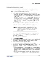
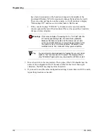
Страница 101: ...ch the console between RUN and PROGRAM modes Move the switch to the program position which is towards the gooseneck MIC and away from the DATA IN DATA OUT and COMB jacks The console display shows PROGRAM 3 Click Send config to position 4 If previous edits to the configuration file have not been saved you will be asked if you want to save them now To proceed click whichever action you prefer 5 Clic...

Страница 102: ...n file If the name of the file has fewer than eight characters the LCD may display extra characters 8 If you need to send the same configuration settings to more than one 4010 console repeat this procedure as needed Warning If the console displays DnLoading CPS or THX 084 after the PC has stopped sending data the console s key definition database has been corrupted and the console will not work un...

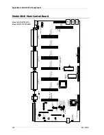
Страница 103: ... mount daughterboard such as the LOTL or Channel ANI Decoders For a list of jumpers and switches see Table 4 on page 27 For a list of potentiometers test points and audio adjustment information see Receive Audio Adjustment on page 42 and Transmit Audio Adjustment on page 45 JP7 JP4 JP2 JP1 JP3 B A B A B A B A B SW1 C A JP6 B C A 1 2 3 4 5 6 7 8 R52 R53 R54 R9 R10 R11 P1 P2 1 26 P3 1 26 Model 4010 ...

Страница 104: ...put Input Headset Remote Terminal Phone Patch Interface Card Spare Inputs Spare Outputs JP8 5 1 5 2 4 2 4 2 4 U27 U29 JP9 Eprom Backup Ram Battery To Display To Lower Keypad To Upper Key Panel U23 Processor Main U15 Generator Paging Function 1 0 1 4 J12 Dual Channel or Aux I O Card J11 Dual Channel or Aux I O Card J10 Dual Channel or Aux I O Card J9 Dual Channel or Aux I O Card J8 Dual Channel or ...

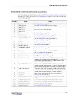
Страница 105: ...phone hook switch See PTT Handset with Cradle on page 77 P4 Tone Remote connector If there is no Tone Remote Card installed four jumpers must be installed across this connector at the following pins 1 2 3 4 5 6 7 8 Either the card or the jumpers have to be installed in order to pass Unselect Select Mic and Patch audio P5 System Wide ANI connector If there is no System Wide ANI Card installed a jum...

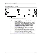
Страница 106: ...is located in the same location R7 Adjusts the unselect speaker bias This is adjusted at the factory Adjusting this incorrectly can lead to a damaged op amp See Display Board Adjustment on page 132 R21 Adjusts the display contrast This is adjusted at the factory and typically does not need adjustment R32 Adjusts the minimum volume of the select speaker Older units may have a different pot number b...

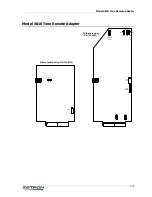
Страница 107: ...odel 4010 Tone Remote Adapter Model 4010 Tone Remote Adapter JP7 JP6 TP2 R47 JP2 JP3 TP1 JP1 1 1 1 GT AUDIO DELAY SEC MIC PATCH DLYD Without audio delay P N 702 9433 JP1 R1 A B With audio delay P N 702 9896 ...

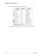
Страница 108: ...1 DELAY 25 25 sec delay JP1 50 50 sec delay JP1 75 75 sec delay JP1 1 0 1 0 sec delay JP2 MIC IN Enable delay JP2 OUT Disable delay JP3 PATCH IN Enable delay JP3 OUT Disable delay Notch Filter Jumpers JP7 PATCH IN Enable notch filter JP7 OUT Disable notch filter JP6 MIC IN Enable notch filter JP6 OUT Disable notch filter The default conditions for the jumpers are in the IN position and 75 seconds ...

Страница 109: ...th CPSW Console Programming System for Windows See Programming on page 79 Main topics in this appendix DC and Tone Remote Function Definitions on page 110 Achieving Motorola GE DC Control Currents on page 111 Paging Format Specifications on page 112 Description of Key Functions and Parameters on page 119 ...

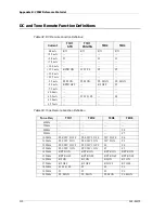
Страница 110: ...ON PL MON 5 0 mA RPTR OFF R2 OFF F3 7 5 mA 10 0 mA 12 5 mA F1 W O PL F4 15 0 mA 15 5 mA Tone Freq T1R1 T2R2 T4R4 T8R8 650Hz 750Hz 850Hz F8 950Hz F7 1050Hz PL4 WC 2 OFF PL4 WC 2 OFF WC 2 OFF F6 1150Hz PL3 WC 2 ON PL3 WC 2 ON WC 2 ON F5 1250Hz PL2 WC 1 OFF PL2 WC 1 OFF F4 F4 1350Hz PL1 WC 1 ON PL1 WC 1 ON F3 F3 1450Hz RPTR ON RPTR ON RPTR ON RPTR ON 1550Hz RPTR OFF RPTR OFF RPTR OFF RPTR OFF 1650Hz ...

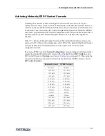
Страница 111: ...eeds Motorola GE standard currents close option switch 6 of the card s configuration switch If the B channel of the Dual Channel Card needs Motorola GE standard currents close option switch 2 of the card s configuration switch Then using CPSW locate the System Configuration menu and program all channels that require the standard Motorola GE currents with a Channel Type of DC Control and a DC Contr...

Страница 112: ...2 524 6 903 2 1433 4 912 0 A none none none none none none 1011 6 B none none none none none none 1122 1 Diagonal Tone 569 1 979 9 569 1 569 1 979 9 979 9 979 9 Tone Tone Groups Number Mot B Mot Z GE A GE B GE C Mot 10 Mot 11 0 371 5 346 0 682 5 652 5 667 5 1472 9 1930 2 1 412 1 384 6 592 5 607 5 712 5 1513 5 1989 0 2 457 1 426 6 757 5 787 5 772 5 1555 2 2043 8 3 507 0 473 2 802 5 832 5 817 5 1598...

Страница 113: ...2 2 2 2 2 2 2 4 3 4 3 3xx 5 1 3 3 3 3 3 3 4 2 4 2 5 2 3 3 3 3 4xx 1 6 4 4 3 2 3 2 4 4 4 4 2 6 4 4 4 4 5xx 5 5 3 2 5 5 2 6 5 5 2 6 5 5 5 5 3 6 6xx 6 6 2 4 2 5 6 6 2 5 6 6 6 6 3 5 6 6 7xx 6 1 4 2 5 2 6 2 4 5 6 2 6 2 4 5 6 3 8xx 5 6 3 4 3 5 3 6 5 4 4 6 5 6 5 4 4 6 9xx 6 5 4 3 5 3 6 3 5 2 6 4 6 5 5 3 6 4 Groups 1 5 6 2 3 4 2 3 4 5 2 3 4 6 2 4 5 2 4 6 2 5 6 2 3 4 5 2 3 4 6 Mot V Groups Mot W Groups Mot...

Страница 114: ... 4 4 569 1 4 4 569 1 4xx 953 7 Mot 4 5xx 5 5 979 9 5 5 979 9 5xx 953 7 Mot 5 6xx 2 1 N A 6 6 979 9 6xx 979 9 Mot 1 7xx 4 5 N A N A N A 7xx 979 9 Mot 5 8xx 5 4 N A N A N A 8xx 979 9 Mot 4 9xx 2 4 N A N A N A Axx2 3 3 569 1 N A N A 1 For General Alternate Code Plan the last two digits of the capcode are the same 2 The General Plan has an eleventh pager block with Capcodes Axx which is not coded on t...

Страница 115: ...84 0 39 1025 0 55 588 0 8 3000 0 24 1723 0 40 990 0 56 568 0 9 2898 0 25 1664 0 41 956 0 57 549 0 10 2799 0 26 1608 0 42 923 0 58 530 0 11 2704 0 27 1553 0 43 892 0 59 512 0 12 2612 0 28 1500 0 44 862 0 60 495 0 13 2523 0 29 1449 0 45 832 0 14 2437 0 30 1400 0 46 804 0 15 2354 0 31 1352 0 47 776 0 Tone Tone Groups Number Z1 Z2 Z3 Z4 Z5 0 1980 0 1177 0 1400 0 832 0 588 0 1 2704 0 1608 0 1912 0 1137...

Страница 116: ...igit encoding shown by x and y reverses position for each 100 pager block In Motorola GE plans the first tone is always the tens digit and the second tone is the ones digit For REACH group call 0xx group is not present Instead ten group calls are accessible using pager numbers 000 011 022 099 These pager numbers generate the ten group call tones from tone group Z1 The group calls activate the firs...

Страница 117: ... No 8 1747 1747 1728 2000 2000 1830 2000 Tone No 9 1860 1860 1869 2200 2200 2000 2200 A Group 2400 1055 2151 2800 885 825 970 C X Tone 2247 2400 2010 970 740 2800 2800 E Repeat 2110 2110 459 2600 970 2400 2600 Timing2 CCIR EEA EIA ZVEI DDZVEI DZVEI PZVEI Preamble 673 673 673 673 673 673 673 Gap 65 65 65 65 65 65 65 Tone 100 40 33 70 70 70 70 X Tone 100 40 65 70 70 70 70 1 Frequencies are shown in ...

Страница 118: ... 1000ms Group call 5000ms if 1st and 2nd tone pairs are same Tone A Series B Series Z Series No Freq 1 1 Frequencies are shown in hertz Code Freq Code Freq Code 0 358 9 CA 371 5 CB 346 7 CZ 1 398 1 DA 412 1 DB 384 6 DZ 2 441 6 EA 457 1 EB 426 6 EZ 3 489 8 FA 507 0 FB 473 2 FZ 4 543 3 GA 562 3 GB 524 8 GZ 5 602 6 HA 623 7 HB 582 1 HZ 6 668 3 JA 691 8 JB 645 7 JZ 7 741 3 KA 767 4 KB 716 1 KZ 8 822 2...

Страница 119: ...red telephone is off hook this key toggles the hold function Frequency Select This key is only applicable with a tone or DC controlled radio with multiple frequency capability By selecting this key the desired frequency command will be sent The current or tone will be sent to the radio in order to select the desired frequency Please note that no current is different from 0 0 ma Selecting 0 0 ma wi...

Страница 120: ...fic channel to be set or changed at the console Pressing the key will cause the current volume level in percentage to be displayed Turning the channel volume knob while holding the key down will cause the volume level to be changed with the new value displayed on the console display Mute Adjust This is a dual function key and is more correctly called the Volume Adjust Mute abbreviated V Adj Mute P...

Страница 121: ...s When audio is received on one of the patched channels the other transmitter s are activated as long as the audio is active The patch keys on at least two channels must be activated in order to have any effect Release This key requires telephone control and thus is only available for channels 13 and 14 The key is used to end a telephone call and thus release the line Main Standby This key activat...

Страница 122: ...ons that can be assigned to Standard Tone and or DC controlled channels CTCSS Select This command activates CTCSS constant tone coded squelch signal over ride This key will cause the PL private line feature to be disabled thereby allowing all radio channel activity to be monitored by the console operator Refer to DC and Tone Remote Function Definitions on page 110 for the actual tone or DC current...

Страница 123: ... for receive and transmit Tone If the channel has been defined as a tone controlled channel you will be asked to select the desired transmit and receive tone The receive tone selected will be sent whenever the key is pressed The transmit function will be sent on transmit System Functions System functions are assigned to individual keys but may affect more than a single channel Transmit Keys The fo...

Страница 124: ... the audio lines as an intercom path When this key is pressed only the audio is sent to the channel the transmitter is not keyed Alert Select a key to generate the desired alert tone to be transmitted to the Selected channel The desired alert will be sent as long as the key is held down All Mute This All Mute function key will cause the audio from all Unselected channels to be muted The selected c...

Страница 125: ...umber for a specific channel or click Select or Transfer Clicking Select will cause the marker to be sent on the Selected channel Clicking T will cause the marker to be sent to the channel of the next select key pressed Simultaneous Select Holding this key and pressing channel Select keys will cause multiple channels to be Selected All the channels thus selected will transmit when the transmit key...

Страница 126: ...g with seconds then minutes hours month day and finally year The display will automatically show the date once the three units of the time of day have been set You may distinguish a time display from a date display by the colon units separator used for time versus the slash units separator used for date Channel Test This key is for diagnostic use only Pressing this key will cause all indicator LED...

Страница 127: ...sole DTMF paging keypad is in progress this function will abort the current key entry sequence and clear the paging display without altering the existing page stack If a page entry is not in progress pressing this key will delete all console page stacks If a page transmission is in progress it will also immediately abort the page transmission This function should always be programmed if the consol...

Страница 128: ...olume Adjust key usable for all channels instead of several Volume Adjust keys one for each channel Phone On Off Hook Transfer This key will activate the auxiliary output line of the next channel Selected It is intended for use as an off hook signal to answer an incoming phone line when the optional telephone is installed Each channel has one auxiliary output line Phone Hook Flash Transfer The pho...

Страница 129: ... will display the AUXILIARY INPUT OUTPUT menu From the menu you may assign an auxiliary input one of three different types of auxiliary outputs or spare outputs Outputs 7 and 8 in Reverse Selective Calling Mode If either a primary or secondary ANI address is programmed see ANI Decode Display on page 97 the console operates in Reverse Selective Calling RSC mode Radios must support one of the follow...

Страница 130: ...d the output will be active when released the output will be inactive Spare Output Spare Output Latching The eight spare outputs are located on pin block P7 When an output is ON its voltage is greater than 3 5 volts DC relative to ground When the output is OFF its state is less than 0 5 volts If Spare outputs 7 and 8 are not reprogrammed Spare Output 7 will be ON whenever an ANI is displayed on th...

Страница 131: ...age should be 3 0vdc or greater If the voltage is lower than 3 0vdc The battery should be replaced soon Removing power may cause the configuration to be lost or corrupted You should have a backup configuration file to reprogram the console If the battery needs replacing contact Zetron to order a replacement See Model 4010 Battery Replacement Instructions P N 011 0789 Firmware Upgrade A firmware up...

Страница 132: ...010 and check the LCD display for contrast quality Adjust R21 on the Display Board for the best contrast 2 Disconnect the Select Speaker from JP3 3 Connect a digital volt meter DVM across JP3 and adjust R34 until the DVM reads 0 0 0 02 VDC 4 Remove the DVM and reconnect the Select Speaker to JP3 5 Disconnect the Unselect Speaker from JP1 6 Connect a digital volt meter DVM across JP1 and adjust R7 ...

Страница 133: ...0 N 8 1 no flow control The battery is too weak or has died Check the battery voltage and replace if necessary See Battery Check Replacement on page 131 The configuration is invalid Use CPSW to send a known valid configuration to the console See Programming on page 79 Scratchy or no audio on older consoles Older consoles may suffer from oxidation on the P4 connector pins see Model 4010 Dual Channe...

Страница 134: ...Appendix D Troubleshooting 134 025 9227S ...

Страница 135: ...bit 28 Button labeling 39 C Channel ANI Decoder 67 Channel Configuration 85 Channel Cross Mute 29 Channel Functions 119 Custom 123 Extended 122 Channel Test button 126 Channel VOX Hang Time 30 Channel Wiring 31 Clock Set button 126 Coded Clear button 122 Connectors 105 Console Programming 79 Control Board jumpers and switches 24 CPS 79 CPSW 79 CPSW Menu Structure 81 Cradle 77 Cross Busy I O wiring...

Страница 136: ...lation Sequence 15 Instant Call button 127 Instant Select button 120 Instant Select with Voting button 120 Instant Transmit button 120 J Jackbox 50 K Key Definitions 94 Key Functions and Parameters 119 L Labeling 39 Last Call Transmit Any Channel button 124 Last Call Transmit Selected Channels button 124 Last Call Transmit Unselected Channels button 124 Level Adjustments 42 Line Termination 28 Loc...

Страница 137: ...Q Quick Call One Two Plus Two Frequencies and Timing 118 R Reach encoding 115 Receive audio adjustment 42 Receive Audio wiring 32 Release button 121 Repeat On Off button 122 Reverse Selective Calling Mode 129 RX level adjustment 42 S Second Receiver Unmute Mute button 122 Secondary Headset Jackbox 50 Select button 119 Simplex operation 29 Simultaneous Select button 125 Site Intercom button 121 124...

Страница 138: ...oubleshooting 133 TX Timeout 92 V Volume Adjust Knob 120 Volume Adjust Transfer button 128 Volume Adjust button 120 Volume and Mute Keys 120 Volume Down button 121 Volume Mute button 121 Volume Reset button 124 Volume Up button 120 W Wild Card I On Off button 123 Wild Card II On Off button 123 ...

Отзывы: