background image

PREMIER EVACS 1-16 INSTRUCTION MANUAL: 2-ZONE NETWORKED VOICE ALARM PANEL 


Document no: GLT-237-7-1 


PAGE 29 

Issue: 1.5 

Date: 02/04/2014 

Consider a system consisting of: 
 

1x 12W speaker system 
1x 8W speaker system 
100mA equipment draw on Aux power 
300mA equipment draw on Aux power during alarm 
480mA sounder channel 1 
360mA sounder channel 2 
 
-


The system must remain on standby for 24 hours 

-


The system must also be able to handle the alarm condition for a minimum of 1 hour 


Referring to the audio output power graph – 
 

The 12W speaker system will have a maximum current draw of about 1.4A 
The 8W speaker system will have a maximum current draw of about 1.1A 


Standby requirements


Quiescent current 

0.06A   


Auxiliary equipment  

0.1A   


Total standby current 

0.16A 

x standby time of: 

24h 

3.84 Ah 

(1)


Alarm requirements


System current 

0.5 A   


Auxiliary equipment 

0.3 A   


Sounder circuit 1 

  0.48 A   


Sounder circuit 2 

 0.36 A   


Audio channel 1 

1.4 A   


Audio channel 2 

1.1 A   


Total Alarm current 

4.14 A 

x alarm time of: 

1 h 

4.14 Ah 

(2)


Total capacity requirements 


Sum of 

(1)

 and 

(2)


(1) 

3.84 Ah 

(2) 

4.14 Ah 

7.98 Ah 

(3)


Minimum battery capacity 

(3) 

7.98 Ah


x 1.25 

9.975 Ah 


The next battery capacity upwards from this is 12Ah, which would be suitable for this installation. 


Содержание PREM1ER EVACS 1-16

Страница 1: ...PREMIER EVACS 1 16 INSTRUCTION MANUAL 2 ZONE NETWORKED VOICE ALARM PANEL Document no GLT 237 7 1 PAGE 1 Issue 1 5 Date 02 04 2014 PREM1ER EVACS 1 16 INSTALLATION MANUAL ...

Страница 2: ... Mounting the voice evacuation panel 9 Planning cable entry 9 Wiring the PCB 10 Display Controls 11 Display 11 Controls 12 Speaker circuits 12 Sounder circuits 12 Networking the panel 13 Connecting the EVACS 1 16 to an analogue addressable panel 15 Address settings 16 Configuring the Voice Messages and Trigger Inputs 17 Alarm Configuration 18 Alert Configuration 19 Mic Configuration 19 Batch Load ...

Страница 3: ...a Voice Alarm Condition 25 Fault display fault finding 26 Fault Finding 26 Power Supply fault 26 Loss of Mains power 26 Loss of Battery power 26 Loss of Charger 26 Speaker Circuit Fault 27 Speaker Circuit Open Circuit fault 27 Speaker Circuit Short Circuit Fault 27 Speaker Failure 27 Earth Fault 27 Amp Fault 27 System Fault 27 Specifications 28 ...

Страница 4: ...VACS 1 16 configuration software lets you easily customise and program the panels features including volume control trigger matrix microphone configuration as well as downloading of bespoke alert and evacuate messages of up to a minute long each The pre recorded message can be initiated via the built in keypad via the remote trigger inputs or via the loop interface The remote trigger inputs and th...

Страница 5: ...t damage to the sensitive electronic components on the display board and the control board due to electrostatic discharge If anti static equipment such as an anti static wrist strap is not available you should discharge any static electricity you may have accumulated by touching a convenient earthed object such as an unpainted copper radiator pipe You should repeat the process at regular intervals...

Страница 6: ...nd transporting batteries DANGER Do NOT attempt to remove the battery lid or tamper with the internal workings of the battery Electrolyte is a highly corrosive substance and presents significant danger to yourself and to anything else it touches In case of accidental skin or eye contact flush the affected area with plenty of clean fresh water and seek immediate medical attention Valve Regulated Le...

Страница 7: ...cessarily It should be mounted at eye level in order for it to be viewed without need of a ladder It should be installed in a dry weatherproof place away from direct sunlight It should be easily accessible so that the responsible person can perform their regular fire alarm checks Fixing the back box to the wall Plan view of enclosure Side view for surface installation Dimensions mm Fix the enclosu...

Страница 8: ...ification of EN 50200 including the 120 min survival time of BS 8434 2 Note that all cables should be at least 1mm2 cross section On the Premier EVACS 1 16 Panel the general recommendation would be to use standard fire resistant cable such as GLT Exports Fire Defence Cable Firetuff FP200 or an equivalent These cables are screened and will provide good EMC shielding when properly grounded at the pa...

Страница 9: ...ixing the back box to the wall Planning cable entry The figure below shows the location of the cable entries to facilitate planning of wiring to be brought to the panel If a cable entry push out is removed fill the hole with a brass cable gland If any knockout is removed but subsequently not used it should be covered up using a 20mm blanking grommet The 230V AC Mains cable must be fed into the enc...

Страница 10: ... connection to an analogue control panel such as the Premier Quatro Fault relay Connection to the fault relay this is normally energised when the system is functioning correctly Alert Trigger input for the Alert signal Evacuate Trigger input for the Evacuate signal Aux Auxiliary power output Network Network connection to other EVACS 1 16 panels Microphone input Connects to the panels microphone Ch...

Страница 11: ...blem EARTH FAULT YELLOW The system has detected a wiring fault shorting to earth AMP FAULT YELLOW There is a problem with one of the systems amplifiers COMMON FAULT YELLOW There is a fault on the system Check specific LED for further information COMMON ALARM RED The system is playing the pre recorded alert message DISABLEMENT YELLOW A zone has been disabled MIC ACTIVE RED The panels live emergency...

Страница 12: ...of a selected message or to stop an existing message 1 16 Select buttons for channels 1 to 16 Speaker circuits The EVACS 1 16 has two 667Ω speaker outputs running at 100v nominal allowing up to 30W RMS output per channel Wiring the speakers Te premier EVACS II checks for line integrity by using a 10K End of Line resistor on each speaker circuit which should be connected to the last speaker on the ...

Страница 13: ...ard The master panel or a panel which is not part of a network must be set an address of 1 Address SW1 SW2 SW3 SW4 1 Master or stand alone panel OFF OFF OFF OFF 2 OFF OFF OFF ON 3 OFF OFF ON OFF 4 OFF OFF ON ON 5 OFF ON OFF OFF 6 OFF ON OFF ON 7 OFF ON ON OFF 8 OFF ON ON ON 9 ON OFF OFF OFF 10 ON OFF OFF ON 11 ON OFF ON OFF 12 ON OFF ON ON 13 ON ON OFF OFF 14 ON ON OFF ON 15 ON ON ON OFF 16 ON ON ...

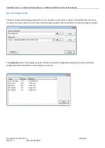
Страница 14: ... via the USB link To set the number of zones connect the PC to the EVACS 1 16 panel via a suitable USB cable and run the EVACS 1 16 configuration software Note that the panel must be powered on In the configuration software select settings select the desired number of zones and click OK The panel should now be configured with the correct number of zones SWITCH ON OFF Notes SW5 RESERVED RESERVED RE...

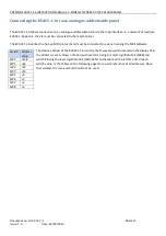
Страница 15: ...lises the Fyreye MKII protocol and must be connected to a panel running the MKII software The device address of the EVACS 1 16 is set by the 8 way dip switch located on the display PCB the address is set in binary notation with switch 1 being the most significant bit MSB and switch 8 being the least significant bit LSB Refer to the table on the left for a list of each switch value or the tables on...

Страница 16: ...ON OFF ON 157ON OFF OFF ON ON ON OFF ON 221 ON ON OFF ON ON ON OFF ON 30OFF OFF OFF ON ON ON ON OFF 94OFF ON OFF ON ON ON ON OFF 158ON OFF OFF ON ON ON ON OFF 222 ON ON OFF ON ON ON ON OFF 31OFF OFF OFF ON ON ON ON ON 95OFF ON OFF ON ON ON ON ON 159ON OFF OFF ON ON ON ON ON 223 ON ON OFF ON ON ON ON ON 32OFF OFF ON OFF OFF OFF OFF OFF 96OFF ON ON OFF OFF OFF OFF OFF 160ON OFF ON OFF OFF OFF OFF OF...

Страница 17: ...els most settings are only available to the panel configured as master On the Premier EVACS 1 16 alert and evacuation messages can be uploaded from a PC running the configuration software The messages cannot be recorded direct to the panel due to the microphones limited dynamic range which would result in poor quality pre recorded messages Any suitable Audio file can be uploaded The file format is...

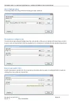
Страница 18: ... dialogue allows the user to upload a custom alarm message it also allows the user to set the alarm tone used which is a short tone intended to grab people s attention before the alarm messages is played The Readback button on this dialog as well as the other audio file configuration dialogs will read the audio file configuration from the EVACS 1 16 and display it on screen ...

Страница 19: ... Microphone Configuration The microphone signon signoff dialog allows the customisation of the sign on and sign off tones these are short tones or custom announcements that are played when the microphone is activated and de activated respectively Batch Load Audio Files A batch load option is available for the convenience of vendors who may work on multiple EVACS 1 16 systems utilising the same cus...

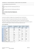
Страница 20: ...iles to be played for the sign on and sign off for the microphone Comms section specifies the communications parameters The communications port the EVACS 1 16 panel is detected on should be displayed in the lower left of the EVACS software main screen List of available tones Tone Type Primary f1 start frequency Hz Secondary f2 end frequency Hz Sweep duration mS On Period or f1 time mS Off period o...

Страница 21: ...CS 1 16 INSTRUCTION MANUAL 2 ZONE NETWORKED VOICE ALARM PANEL Document no GLT 237 7 1 PAGE 21 Issue 1 5 Date 02 04 2014 Channel Volume This provides a volume control interface to set the output volume of each zone ...

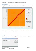
Страница 22: ...er input In this example the zone activated will go into alarm whilst all other zones will go into alert however it is possible to set a variety of configurations using this interface When you are happy with the configuration be sure to click on the Send button to upload the trigger matrix to the panel Settings From here you can set the number of zones configured on a network Select 1 for a standa...

Страница 23: ...NSTRUCTION MANUAL 2 ZONE NETWORKED VOICE ALARM PANEL Document no GLT 237 7 1 PAGE 23 Issue 1 5 Date 02 04 2014 Status Monitor This displays the status of all nodes on the network and reports any errors that may be present ...

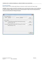
Страница 24: ... version of the currently loaded firmware and provides a utility to update the firmware image WARNING firmware updates should NOT be attempted unless under the specific instruction of the manufacturer An incorrect firmware update may cause the panel to operate outside its design and conformity specifications and may even cause permanent damage to the panel ...

Страница 25: ...d via the PC Software Sample configurations are Play evac alarm on selected zone Play evac alarm on selected zone and alert on all other zones Play evac alarm on selected zone and alert on floor above floor below As shown above the number of zones operated will depend on the configuration of the remote inputs Resetting from a Voice Alarm Condition The EVACS 1 16 can be reset in various ways depend...

Страница 26: ...y will clear automatically when the fault has been fixed Fault Finding Power Supply fault A power supply fault is indicative of one or more of the following faults Loss of Mains power Check that 230V AC is present at the mains terminal block Check mains fuse Check charger fuse FS1 Loss of Battery power Check that 2 X 12V batteries are fitted in series to give 24V backup Check battery fuse Check th...

Страница 27: ...Because the Premier EVACS 1 16 monitors the speaker circuits for a change in impedance the system can usually detect a broken speaker For example a broken wire to the drive cone will not affect the speaker line s continuity but it will affect its impedance Presently the only way to check for this is by verifying sound output at each speaker on the speaker circuit reporting the fault Earth Fault Th...

Страница 28: ... the audio system it is important to note that the relationship between output power volume and power drain is non linear and may differ depending on the message store used The following graph shows the typical current drawn by a single audio channel based on the output power Standby current will consist of the quiescent current draw of the panel plus the current draw of any equipment connected to...

Страница 29: ... The 12W speaker system will have a maximum current draw of about 1 4A The 8W speaker system will have a maximum current draw of about 1 1A Standby requirements Quiescent current 0 06A Auxiliary equipment 0 1A Total standby current 0 16A x standby time of 24h 3 84 Ah 1 Alarm requirements System current 0 5 A Auxiliary equipment 0 3 A Sounder circuit 1 0 48 A Sounder circuit 2 0 36 A Audio channel ...

Страница 30: ...ments Quiescent current A Auxiliary equipment A Total standby current A x standby time of h Ah 1 Alarm requirements System current A Auxiliary equipment A Sounder circuit 1 A Sounder circuit 2 A Audio channel 1 A Audio channel 2 A Total Alarm current A x alarm time of h Ah 2 Total capacity requirements Sum of 1 and 2 1 Ah 2 Ah Ah 3 Minimum battery capacity 3 Ah x 1 25 Ah When selecting the correct...

Страница 31: ...layed and may push the system beyond its recommended operating parameters Volume controls Please note that maximum output of the unit is indicative only and that setting the unit beyond the maximum recommended ratings may degrade audio performance Actual output power will vary depending on the speaker system installed 0 01 0 10 1 00 10 00 100 00 40 32 24 16 8 0 Max RMS output Power W Volume settin...

Страница 32: ...r consumption vs Output power Main power 29 5V Backup Power 23 7V 1KHz continuous sine wave 0 20 40 60 80 100 120 140 160 180 200 64 56 48 40 32 24 16 8 0 Power Consumption W Volume per channel dB Power consumption vs Volume setting Main Power 29 5V Backup Power 23 7V 1KHz continuous sine wave 0 1 2 3 4 5 6 7 0 10 20 30 40 50 60 Current consumption A Output power channel W Current consumption vs O...

Страница 33: ...E VOLTAGE 100V NOMINAL MINIMUM SPEAKER IMPEDANCE 600Ω 1KHz MINIMUM RESISTIVE LOAD 1260Ω MAXIMUM CAPACITIVE LOAD 110nF OUTPUT PER CHANNEL MAX 30W TOTAL OUTPUT MAX 60W ALARM OUTPUT 2 x 500mA 28V DC FAULT OUTPUT 1X RELAY SELV NORMALLY ENERGISED PANEL INPUTS 1X ALERT 1X EVACUATE DESCRIPTION VALUE DIMENSIONS h x w x d 475 5 x 400 x 143mm WEIGHT 7 1Kg TOP CABLE ENTRIES 28 BOTTOM CABLE ENTRIES 6 FUSE NO ...

Отзывы: