


There is a dedicated terminal for the live and neutral of each output
circuit. Channels 1 to 12 are on the left hand side, and channels 13 to
24 are on the right hand side. A shared Earth bus bar is mounted on
the chassis of the dimmer for channels 1-12, and a separate bus bar
for 13-24.
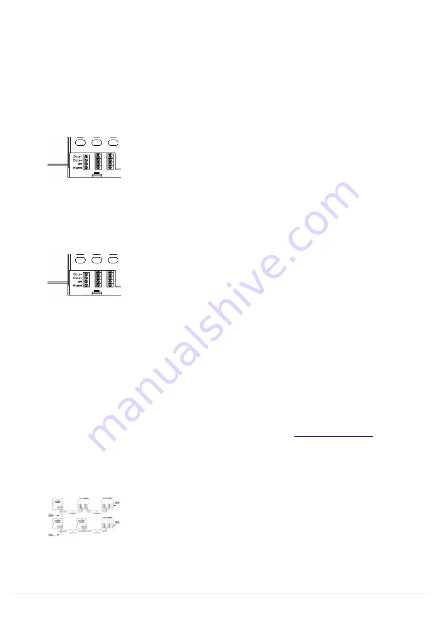
Connecting DMX
DMX input is connected through a 4-way screw terminal block located
on the control PCB.
To loop through to another dimmer, simply connect both sets of wires
into the same terminal block.
The terminals to be used are labelled RS485-, RS485+ and 0V.
Alarm input
The Alarm Input is connected through a 4-way screw terminal block
located on the control PCB (Figure 2-15).
The terminals to be used for the Alarm Input are labelled 0V and AL.
Any connection to the Alarm Input must be volt free and have a cable length of less than 50 metres. Cabling for this
input should be segregated from power wiring.
The connector is in two parts and the screw terminal part may be removed from the PCB to ease making the
connections. If removed for wiring, ensure that the orientation is correct when replacing the connector.
Connecting ChilliNet
Chilli Pro dimmers can be connected to Chilli Control Panels over ChilliNet. Other
compatible.
Each ChilliNet device has a set of network terminals or an RJ12 socket provided for connection to the Chilli network.
The cable used to connect the various devices in the network must be CAT 5 (100MHz) FTP cable.
This is an example ChilliNet system, featuring Chilli Control Panels
and Chilli Pro dimmers.
Zero 88 - Chilli Pro - Page 10 of 60
Printed: 23/03/2021 09:13:40 ES