zero
HOME AUTOMATION
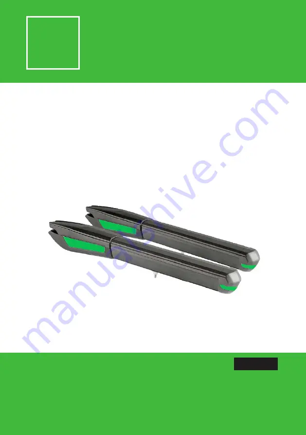
Z03 - SWING GATE
PG1
USER MANUAL AND CONFIGURATION
Z03.REV01.2018
IT | EN | FR
Z03 - SWING GATE MOTOR
SUPPLY 230-24V
Страница 1: ...zero HOME AUTOMATION Z03 SWING GATE PG1 USER MANUAL AND CONFIGURATION Z03 REV01 2018 IT EN FR zero HOME AUTOMATION Z03 SWING GATE MOTOR SUPPLY 230 24V ...
Страница 2: ...zero HOME AUTOMATION Z03 SWING GATE PG2 zero HOME AUTOMATION ...
Страница 3: ...ERO SRLS is not responsible for the improper use of the product or other use than that for which it was designed ZERO SRLS is not responsible if safety standards were not taken into account when instal ling the equipment or for any deformation that may occur to it ZERO SRLS is not responsible for the safety and proper operation when using components not sold by them Do not make any modifications t...
Страница 4: ...00 400 600 dimensions are the following Z03 Z02 24 Power Supply 230Vac 50 60Hz 24Vdc Power 300W 80W Current 1 4 A 3 A Capacitor 12 5µF RPM 1400 1650 Noise level LpA 50 dB A Force 2800 N Operating temperatures 25 C to 65 C Thermal protection 120 C Protection class IP23 Working frequence 25 INTENSIVE Opening time 13 18 seconds ...
Страница 5: ...e from the floor to the top of the rear support Dimension B Vertical distance from the floor to the top of the front support Example Set dimension A this can be any size of your choice After you set dimension A subtract 56mm to find dimension B If the height of the rear bracket dimension A is set at 600 mm then the height of the front bracket dimension B will be 544 mm 600mm 56mm It is very import...
Страница 6: ...for the installation of the automated system Legend Dimension X Horizontal distance between hinge axis of the door and the rear axle of the motor Dimension Y Vertical distance between hinge axis of the door and the rear axle of the motor Dimension W Distance between axis of the motor brackets 770mm ...
Страница 7: ...s Legend Dimension X Horizontal distance between hinge axis of the door and the rear axle of the motor Dimension Y Vertical distance between hinge axis of the door and the rear axle of the motor Dimension W Distance between axis of the motor brackets 770mm During the installation process it is required to respect the dimensions that are within the hi ghlighted area ex y 190 x 180 ...
Страница 8: ...r supports 03 Install the pins removed earlier on each side with a small amount of lubricant for lessfriction Unlock the motor and move the door manually to see if the door opens and closes uniformly and correctly wi thout any irregular friction during its entire movement This will ensure that the motor is not subjected to problems during ope ration 04 Connecting operator to control board and conf...
Страница 9: ...be damaged It is important to use junction boxes for connections between motors components and control unit All cables must enter and exit on the bottom of the junction and control board box 01 Connect the 3 automation wires in the terminal 02 Connect the two automation white wires with the capacitator wires 03 Connect the power supply wires in the opening the motor will rotate one way and during ...
Страница 10: ...n the pillars and gate to ensure proper functioning of the equipment Lubricate pins Place a small amount of lu bricant on the holes that contains support pins 04 MAINTENANCE Check motor supports Make sure that supports remain well fixed on the pillars and gate to ensure proper functioning of the equipment These maintenance measures must be applied every year in order to insure proper functioning o...
Страница 11: ...zero HOME AUTOMATION Z03 SWING GATE PG11 ...
Страница 12: ...sn t close Unlock motor and move the gate by hand to closed position Lock motor again and turn off power supply for 5 se conds Reconnect it and send start signal using transmitter Gate opened but didn t clo se again Check if there is any obsta cle in front of the photo cells Check if any of the control devices key selector push button video intercom etc of the gate are jam med and sending perma ne...
Страница 13: ...there is some security systems malfunction photocells safety edges etc 1 Close with a shunt all safety systems on the control board check manual of the control board in question If the automated system starts working normally check for the problematic device 2 Remove one shunt at a time until you find the malfunction device 3 Replace it for a functional device and check if the motor works correctl...
Страница 14: ..._____________________________________________________ _____________________________________________________________________ _____________________________________________________________________ _____________________________________________________________________ _____________________________________________________________________ __________________________________________________________________...
Страница 15: ...zero HOME AUTOMATION Z03 SWING GATE PG15 zero HOME AUTOMATION ...
Страница 16: ...zero HOME AUTOMATION Z03 SWING GATE PG16 zero HOME AUTOMATION ZERO SRLS Via ROMA 25 A ALTAVILLA VIC ITALIA info miozero it www miozero it ...