background image

Revision Date – 15/07/2020 


page 25  

8.2  Test AC Rectifier 


WARNING: This test should only be performed by a licensed electrician. 


Both the DC power supply and AC power supply are controlled via the AC rectifier unit.  If the fridge is 

not receiving adequate power from the supply source, it is recommended to first eliminate the AC 

rectifier as the possible cause. 


TEST ON AC POWER 


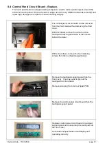
Remove the front cover as described in Section 

9.3

. 


Plug the AC power plug into the front of fridge and 

turn the fridge on. 


WARNING: 

Certain components inside the fridge will be 

live 100-240VAC.  Contact with these 

components may cause serious injury or 

death.  Please be very careful not to contact or 

touch any components other than described 

in this instruction. 


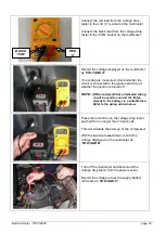
Take a multimeter and set the display to DC 

voltage. 


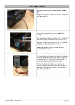
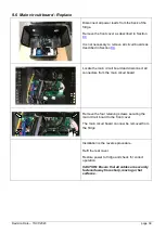
Locate the compressor control unit on the left 

hand side of the fridge connected to the 

compressor. 


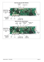
With the multimeter terminals, insert the negative 

terminal into the black wire at the top “-“. 


Insert the positive terminal into the red wire, 

second from the top “+”. 


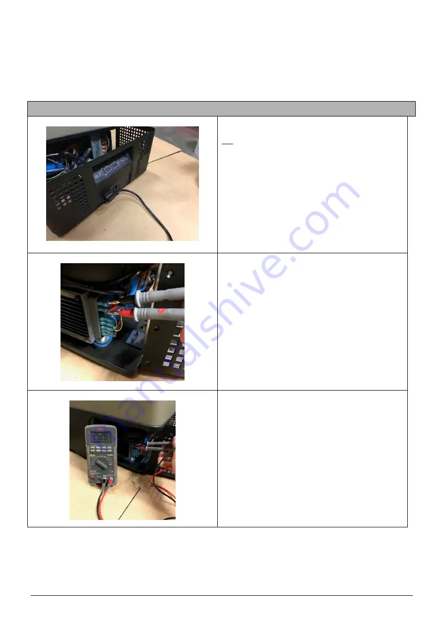
The multimeter will display the voltage produced 

from the AC rectifier.  Typically, this voltage 

should be 24VDC which indicates the AC rectifier 

is working correctly for AC rectification. 


The 12VDC will also need to be checked.  Please 

follow the steps below to complete this test. 


Содержание ARB

Страница 1: ...SERVICE MANUAL ZERO Single Zone Models 36L 38qrt 44L 46qrt 60L 63qrt 73L 77qrt 105L 111qrt Dual Zone Models 69L 73qrt 96L 101qrt...

Страница 2: ...un on 100 240V AC power 20 7 2 Fridge will not run on 12 24V DC power 21 8 CHECKS AND TESTS 22 8 1 Vehicle wiring system 22 8 2 Test AC Rectifier 25 8 3 Test Compressor control unit 12 24V DC 28 8 4 T...

Страница 3: ...working practices must be exercised while performing any work on an ARB Fridge Freezer 1 2 How to use this manual This manual has been developed as an electronic resource To navigate through this man...

Страница 4: ...e eg scratches dents stain etc and documented on the application 2 Assess the fridge to identify the fault s 3 Complete a copy of the warranty claim form and forward it to your regional ARB Office To...

Страница 5: ...red Light LED is only covered under warranty for the first 3 months after the initial purchase date ARB will not pay for the removal or replacement of a fridge freezer that has been built in unless au...

Страница 6: ...MBLY REAR ZERO 36 44L 1 kit 10910182 23 HANDLE SUPPORT BRACKET ZERO 36 44L 1 kit 10910183 24 HANDLE SUPPORT BRACKET ZERO 60 69 73 96 105L 1 kit 10910184 25 RUBBER FOOT ZERO 1 10910185 26 DRAIN PLUG 1...

Страница 7: ...Revision Date 15 07 2020 page 6 4 2 Spare parts exploded drawing The items in the following exploded diagram correspond with the items in the table in section 4 1...

Страница 8: ...58 74 MAIN PCB ZERO DUAL ZONE 1 10910219 75 INTERIOR LIGHT PCB ZERO 1 10910170 76 DC SOCKET COVER ZERO 1 10910198 77 VENT SHROUD SCREWS BASE ZERO 1 10910205 78 FRIDGE BASE PLUG ZERO 1 10910212 79 THER...

Страница 9: ...ble Short length of insulated wire terminated with spring loaded clips or push on connectors at each end The following tools will be required to perform specific non refrigeration based servicing of t...

Страница 10: ...e freezer off because the fan is drawing more than 0 6 amp while the compressor is running This could be because the fan is running slowly or not running at all Check that the fan is not obstructed or...

Страница 11: ...g is correct and that power is available at the outlet socket The DC supply voltage is below the minimum voltage needed to operate the fridge Connect the fridge to a 12 or 24V DC power supply Check th...

Страница 12: ...if necessary refer to section 9 4 Faulty main circuit board Test compressor control unit refer to section 8 3 If control unit is ok test fridge with new main circuit board and replace if necessary re...

Страница 13: ...voltage and voltage at supply socket NOTE Voltage readings must be taken with a load on the circuit to allow for voltage drop within the circuit refer to section 8 1 Check that plug is correctly inst...

Страница 14: ...ed to the compressor control unit Check the fan wiring to ensure the ve and ve fan wires are correctly connected to the compressor control unit refer section 9 9 Faulty fan Test with new cooling fan r...

Страница 15: ...electrician Faulty main circuit board Test with new main circuit board If symptom resolved replace circuit board refer to section 9 6 Faulty compressor control unit Test compressor control unit on AC...

Страница 16: ...ssor and condenser If a leak is detected contact a qualified refrigeration mechanic for service advice If no leak detected contact a qualified refrigeration mechanic and request that the system is pre...

Страница 17: ...ze with fridge set to warmest setting Faulty thermistor Test thermistor refer to section 8 4 and replace if necessary refer section 9 10 Faulty control panel circuit board Test fridge with new control...

Страница 18: ...y main circuit board Test fridge with new main circuit board and replace if necessary refer to section 9 6 Insufficient charge of refrigerant in compressor system Contact a qualified refrigeration mec...

Страница 19: ...customer that latch must be correctly closed before transportation Faulty latch Inspect latch and latch pivot for damage Lid will not open when fridge is running The air inside the fridge has cooled f...

Страница 20: ...f voltage 12V DC 10 1 0 3 V 11 4 0 3 V 11 8 0 3 V Restart voltage 12V DC 11 1 0 3 V 12 2 0 3 V 12 6 0 3 V Switch off voltage 24V DC 21 5 0 3 V 22 5 0 3 V 23 0 0 3 V Restart voltage 24V DC 23 0 0 3 V 2...

Страница 21: ...TO DC TESTING TEST COMPRESSOR CONTROL UNIT YES YES FRIDGE DOES NOT RUN Contact ARB for technical advise IS THE MAIN CIRCUIT BOARD FAULTY IS THE COMPRESSOR CONTROL UNIT FAULTY YES NO YES NO CHECK DEVIC...

Страница 22: ...nic for assistance NOTE THIS IS EXTREMELY UNLIKELY RECONNECT CONTROL UNIT YES YES NO YES COMPRESSOR DOES NOT RUN Contact ARB for technical advice YES CHECK BATTERY PROTECTION SETTING CHECK VEHICLE WIR...

Страница 23: ...some 12V vehicle wiring systems the voltage drop between the battery and the rear factory accessories socket can exceed 2V DC It is important that the vehicle is not running while these voltage readi...

Страница 24: ...gnition is turned off NOTE ARB recommend that a dedicated wiring circuit be used to connect the fridge directly to the battery via a suitable fuse Refer to the wiring advice below Press the red button...

Страница 25: ...he circuit should be connected directly to the negative terminal of the battery It should not be grounded directly to the vehicle body or chassis B Check that all terminals and joints are clean and in...

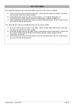
Страница 26: ...40VAC Contact with these components may cause serious injury or death Please be very careful not to contact or touch any components other than described in this instruction Take a multimeter and set t...

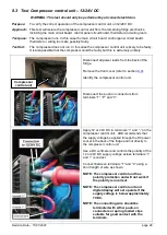
Страница 27: ...e compressor With the multimeter terminals insert the negative terminal into the black wire at the top Insert the positive terminal into the red wire second from the top The multimeter will display th...

Страница 28: ...omprehensive check on all other potential causes the AC rectifier may be the cause and should be replaced The measured DC voltage is considerably less than the supply voltage A Remove the DC power sou...

Страница 29: ...ads from the back of the fridge Remove the front cover refer to section 9 3 Identify the compressor control unit Disconnect the push on connectors from terminals T P and C Apply 12 or 24V DC to termin...

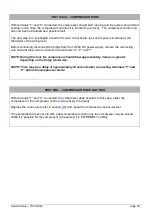
Страница 30: ...refit the push on connectors to terminals C P and T NOTE During this test the compressor should draw approximately 3 amps or greater depending on the fridge model size NOTE There may be a delay of ap...

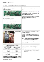
Страница 31: ...istance between the two metal contacts in the plastic connector plug as shown NOTE The resistance of the thermistor will increase as the fridge gets colder Measure the temperature of the plastic liner...

Страница 32: ...he internal temperature calibration should not be changed Procedure Connect the fridge to 12 24V DC or 100 240V AC Turn the fridge on Press and hold and simultaneously until A 0 appears on the display...

Страница 33: ...ND REPAIR 9 1 Handles Replace With Allen key remove all six fasteners securing the handle assembly Remove the plastic handle assembly With Allen key remove all four fasteners securing the handle suppo...

Страница 34: ...off the fridge and remove easily To refit corner columns To refit column align column on corner of fridge Hold firm in position and install the top fastener and tighten loosely Insert the remaining th...

Страница 35: ...er as described in Section 9 2 Remove the side screws from the front cover There are three screws on each side of the front cover Remove the base screws from the front cover There are twelve 12 screws...

Страница 36: ...the power supply panel Remove four screws and pull the power supply panel from the front cover To remove the touchpad panel first peel back the decal with thin blade This will allow access to four sc...

Страница 37: ...for the touchpad and power supply Insert all wire terminals into their correct position Flip the front cover back over the fridge cabinet as shown Fasten the front cover to the body of the fridge usi...

Страница 38: ...ing the front cover With thin blade remove the corners of the touchpad decal to gain access to the screws behind the decal With screw driver remove the four retaining screws from the touchpad support...

Страница 39: ...terminals Remove two mounting screws securing the compressor control unit to the side of the compressor Pull the compressor control unit away from the compressor as per the arrow shown Remove the thr...

Страница 40: ...9 3 Locate the main circuit board and disconnect all connectors from the main circuit board Remove the four retaining screws securing the main circuit board to the front cover The main circuit board...

Страница 41: ...NET LIGHT THERMISTOR COMPRESSOR CONTROL UNIT FAN USB EMERGENCY OVERIDE SWITCH DC JUNCTION BOX COMPRESSOR CONTROL UNIT LIGHT FRONT THERMISTOR REAR DISPLAY PCB DC JUNCTION BOX COMPRESSOR CONTROL UNIT TH...

Страница 42: ...e plate To do this you will need to hold the top securing nuts with a spanner It is recommended to the prop the compressor while doing this as the compressor is quite heavy and will damage other compo...

Страница 43: ...age 42 With screw driver remove all remaining screws securing the base plate to the fridge cabinet and column The compressor base plate can now be removed To refit the new base reverse the process as...

Страница 44: ...n Section 9 7 Pull out the AC Rectifier assembly to gain access to the assembly Remove the plastic cover by unscrewing the four retaining screws Remove the AC Rectifier PCB from the plastic housing by...

Страница 45: ...d remove the wires connected to the AC power socket Disconnect and remove the wires connected to the Main PCB The AC Rectifier can now be removed from the fridge To refit the AC Rectifier reverse the...

Страница 46: ...been confirmed Remove fan retaining screws that secure the fan to the condenser CAUTION Take care not to stretch the refrigeration lines or power cables Remove fan Install the new fan and fasten to th...

Страница 47: ...zone fridges there are two thermistors The longer thermistor cable is for the rear zone and the shorter thermistor cable is for the front zone Single Zone main circuit board Thermistor Dual Zone main...

Страница 48: ...nsert the thermistor wire until the mark made in the previous step lines up with the body of the fridge Secure the thermistor wire in place with the P clip screw and sealing compound Install the new t...

Страница 49: ...G10A Reassemble the plug and test for continuity 9 12Device fuse 100 240V AC Replace Remove the AC and DC power leads from the power sockets Remove the fuse insert from the rear panel of the fridge as...

Страница 50: ...e pressure tested If the pressure test identifies a leak the location of the leak should be found To locate the leak the refrigerant system should be split into two sections see below and pressure tes...

Страница 51: ...Revision Date 15 07 2020 page 50 11 WIRING 11 1Wiring diagram Single Zone...

Страница 52: ...Revision Date 15 07 2020 page 51 11 2Wiring diagram Dual Zone...

Отзывы: