


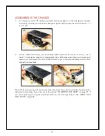


31
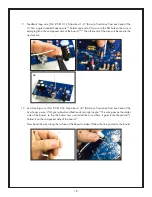
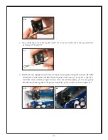
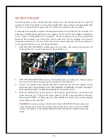
c. Now solder the wires to the lug. Be careful not to use too much heat or the lug could start
melting out of the plastic.
87
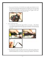
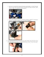
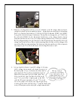
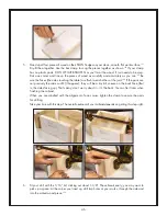
d. Bend both wires slightly forward and push the power receptacle through the chassis. BE SURE
TO INSTALL IT WITH THE CORRECT SIDE UP (look at the picture).
88
It may be a tight fit; it
could take some wrenching to get it to seat. Once it is seated properly, you can very gently
bend the four retaining tabs of the power receptacle up if you want to ensure a tighter fit.
89
87
88
89
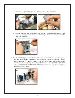
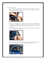
the wire.
82
Thread the hook through the small hole on the grounding lug (Part # CB20) and crimp
it tight with your pliers.
83
Solder that connection.
84
Put this assembly aside until next step.
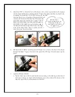
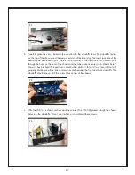
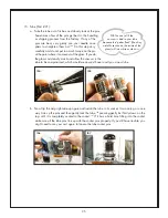
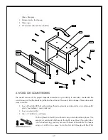
11. IEC Power Receptacle (Part # J3):
a. Strip about 1/4” (6mm) of insulation off the ends of the other 4cm hookup wire (Part #
CB10.3).
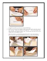
85
Attach the wire to the power receptacle lug as shown, with the wire pointing to
the left away from the power receptacle (study the picture carefully). Use the same hook and
crimp technique that you used in the previous step, but don’t solder it yet. MAKE SURE YOU
ATTACH THE WIRE TO THE CORRECT POWER RECEPTACLE LUG.
b. Now attach the other 4cm wire (the end opposite the ground lug) to the same power receptacle
lug . Attach it so the ground lug is pointing to the right, away from the power receptacle (study
the picture carefully).
86
82
83
84
85
86