


19
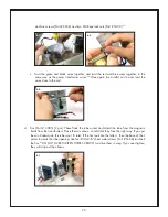
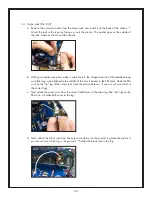
13. 10.5cm Twisted pair hookup wire (Part # CB10.2): This wire is used to transmit the 6.3V heating
filament voltage to the tube. Untwist about 1/4” (6-7mm) of each end of the twisted pair and
straighten the ends out with your pliers.
40
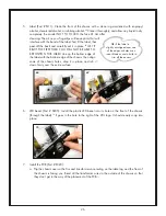
Strip off about 1/8” (3-4mm) insulation from each end
of the two wires.
41
On the solder side of the board, install the four stripped ends in the holes
marked “HEATERS”.
42
It doesn’t matter which wire goes into which of the two holes. Solder each
of the four ends on the component side of the board.
43, 44
40
41
42
43
44
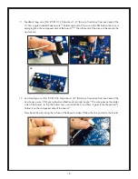
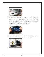
11. Feedback loop wire (Part # CB10.1): Strip about 1/4” (6mm) of insulation from each end of the
10.5cm single stranded hookup wire.
34
Solder one end of this wire to the FBL hole so the wire is
emerging from the component side of the board.
35, 36
The other end of the wire will be used in the
next section.
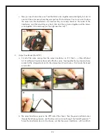
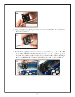
12. 6cm Hookup wire (Part # CB10.4): Strip about 1/8” (3-4mm) of insulation from each end of the
6cm hookup wire. With your pliers bend both ends at a right angle.
37
This wire goes on the solder
side of the board, so flip the board over and install the wire where it goes (note the picture
38
).
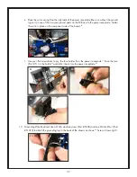
Solder it on the component side of the board.
39
Now bend the wire along the surface of the board to make it follow the line printed on the board.
34
35
36
39