


12
b. Continue with the 220K resistors (R5, R9, R10), labeled RED, RED, YELLOW, GOLD.
c. Continue with the 1.5K (or 1K5) resistors (R7, R14, R17), labeled BROWN, GREEN, RED,
GOLD. R17 has a larger lead spacing than most of the other resistors so estimate where to
bend the leads.
d. Continue with the 47K resistors (R3, R8), labeled YELLOW, VIOLET, ORANGE, GOLD.
e. Continue with the 120 ohm (or 120R) resistors (R12, R15), which are blue in color and are
labeled BROWN, RED, BLACK, BLACK, BROWN.
f. Continue with the 2.2K (or 2K2) resistor (R13), which is also blue in color and is labeled RED,
RED, BLACK, BROWN, BROWN. The lead spacing on R13 is also abnormal, so bend the
leads the proper length to fit into their holes.
6
g. Continue with the 1M resistor (R2), labeled BROWN, BLACK, GREEN, GOLD.
h. Continue with the 820 ohm (or 820R) resistor (R4), labeled GRAY, RED, BROWN, GOLD.
i. Last, install the 4.7K (or 4K7) resistor (R16), labeled YELLOW, VIOLET, RED, GOLD.
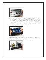
j. You should have a whole forest of bent leads coming out the solder side of the board.
7
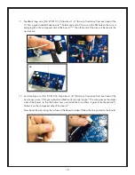
Now
you can turn the board solder-side-up and solder each one to the board.
8
k. Now clip each lead with your flush cutters at the solder joint.
9
l. Before installing any more components on the circuit board, double check the resistance values
of each of the installed resistors. Set your digital multimeter to the “ohms” or “resistance”
setting, and measure across all of the resistors. Compare the measured value to the listed
value in Figure 2 on the previous page.
10
Make sure they are all correct (within 5%) before
moving on!
6
7
8
9
10