background image

1

QUAVERATO TROUBLESHOOTING GUIDE

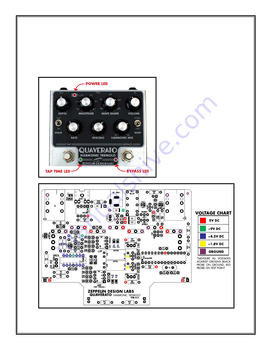
If your Quaverato kit isn’t working properly please read through this guide and follow these steps in 
order. You’ll be required to use your multimeter to test DC voltage, resistance, and continuity on various 
points.

Содержание QUAVERATO

Страница 1: ...TING GUIDE If your Quaverato kit isn t working properly please read through this guide and follow these steps in order You ll be required to use your multimeter to test DC voltage resistance and conti...

Страница 2: ...reads around 1 5V then reverse the probes and check again If when reversing the leads red on round black on square it gives a reading of 1 7V it means the LED is in backwards 2 Does the tap tempo LED...

Страница 3: ...e bypass LED turn on and off as you toggle the bypass foot switch If not A Are the lugs on the bypass foot switch shorted use your continuity tester to see if they are connected when the switch is not...

Страница 4: ...center lug of the VOLUME pot to the tip of the output jack If you don t have continuity between either of these connections there is a problem with the relay circuit Are you able to hear the relay cl...

Страница 5: ...nob fully clockwise A Is the relay properly switching the signal path I With the bypass LED OFF check for continuity between the tip of the input jack and the tip of the output jack Check for good sol...

Страница 6: ...hit your guitar strings hard and then the signal punches through in a distorted burst Most of the time bumping or hitting the pedal against something can help you know if the distortion is caused by...

Страница 7: ...the optocouplers iv Is the optocoupler LED in backwards Check this with your meter s diode tester With the red probe on the LED s square pad and the black probe on the round pad the meter should read...

Страница 8: ...of the pins in each amplifier section and their associated parts Opamp A Pins 1 2 3 with associated parts C3 R21 24 Opamp B Pins 5 6 7 with associated parts C1 R2 R3 R15 Opamp C Pins 8 9 10 with asso...

Страница 9: ...to TP1 If JP2 is bad run a jumper wire from R4 the pin closest to C11 to TP2 If JP3 is bad run a jumper wire from pin 1 of U2 to TP3 If JP4 is bad run a jumper wire from R5 the pin closest to C11 to T...

Страница 10: ...051320...

Отзывы: