background image


16 

3. SPECIAL TOOLS 


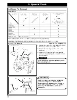
Rod Assy: 3350-96230 

EBZ30 Series, EB4300, EBZ4800, EBZ51 Series 

1.  Remove the engine short block (refer to “3-1 Rotor 

Removal”) and then remove the cylinder. 

2.  Remove the snap rings from both sides of the 

piston pin. 

3.  Insertion the rod assy (special tool) against the 

piston pin and gently tap with a plastic hammer to 
push out the pin. 


Hard hammering may damage the big end of 
the connecting rod. 


Rod Assy: 2750-96230 

EB6200, EB70 Series 

1.  Remove the engine short block (refer to “3-1 Rotor 

Removal”) and then remove the cylinder. 

2.  Remove the snap ring from starter side of the 

piston pin. 

3.  Rest the rod assembly against the end of the piston 

pin and pull the piston pin out from the piston. 


CAUTION 

Rod assy. 

Piston Pin 

Piston 

Rod Assy. 

Piston Pin 

Piston 

Piston Pin 

Snap Ring 

(Don’t remove) 

Snap Ring 

(Remove) 

Snap Ring 

Rod Assy. 

Содержание HB2311EZ

Страница 1: ......

Страница 2: ......

Страница 3: ...enance tasks Frequently asked questions are also included in this manual However many cases need rich maintenance experience and informed judgment Please refer to this manual for maintenance support N...

Страница 4: ...41 5 cm3 47 9 cm3 50 2 cm3 62 0 cm3 64 9 cm3 71 9 cm3 Engine Type G23L GZ25N GZ30N G4K GZ48N GZ51N G62L GZ65N GZ72N JAP HB2311EZ EBZ3000 EB4300 EBZ4800 EB7001 General HB2302 HBZ2601 EBZ3000 EB4300 EB...

Страница 5: ...o confirm engine type and blower model Engine Type G Z 25 N Engine series L N K Displacement cm3 Strato charged engine green engine Blower Model HB Z 26 01 Minor changed code Handheld Bower EB Z 71 00...

Страница 6: ...ston Inserting Direction 24 4 9 Piston Pin Snap Ring Assembly 24 4 10 Positioning of Lead Air Intake Tube 25 4 11 Reed Valve Assembly 25 4 12 Gasket Assembly 26 4 13 Scavenging Duct Cover Assembly 27...

Страница 7: ...ap Removal Installation 44 6 5 Idling Speed Adjustment 44 6 6 Carburetor Inspection 45 6 7 Carburetor Adjustment 47 7 Maintenance Standards 7 1 Engine 51 7 2 Tightening Torques 52 8 Troubleshooting 8...

Страница 8: ......

Страница 9: ...facturer s blower of the same class Large air cleaner employing models EB7000 EB7001 EBZ7100 EBZ8001 Volute Case Frame Guard Net Engine Centrifugal Fan Guard Net Open Vane Fan Closed Vane Fan Backpack...

Страница 10: ...tion Timing rpm 24 6000 35 7000 37 7500 28 7000 35 7000 33 7000 35 7000 28 7000 34 7000 33 7000 Type RCJ6Y CMR7A CMR7H RJ6C CMR7H BPMR7A CMR7H Spark Plug Gap mm in 0 6 0 7 0 024 0 028 Type Primary coi...

Страница 11: ...xible Pipe Swivel Joint Straight Pipe Silencer Pipe End Form Diameter D 87 3 43 87 3 43 94 3 70 99 5 3 92 70 2 76 70 2 76 80 3 15 61 2 40 74 2 91 80 3 15 74 2 91 61 2 40 73 2 84 73 2 87 79 3 11 79 3 1...

Страница 12: ...4300 335 13 2 489 19 3 454 17 9 495 19 5 1222 48 11 EBZ4800 352 13 9 452 17 8 476 18 7 1248 49 13 EBZ5100 5100RH 5150 5150RH 401 15 8 483 19 0 441 17 4 495 19 5 1195 47 05 EBZ5100Q 5150Q 401 15 8 483...

Страница 13: ...nance procedures categorized by type and series are explained below Each drawing includes information on parts such as mount screws and disassembly cautions How to use Procedure Handheld Blower HB23 S...

Страница 14: ...emove the fan 4 Remove the extension using the wrench 5 Remove the four mounting screws separate the volute case and the engine short block Stopper HB23 Series HBZ26 Series Stopper Box Wrench 12 mm Mo...

Страница 15: ...mm Disassembly Flowchart Air Inlet Net Spring Damper Frame Volute Cover Assy Engine Cover Below the procedure Volute Cover Assy Mounting Screw 8 TORX T27 M5 L25 Mounting Screw 3 Mounting Bolt 1 M5 L16...

Страница 16: ...al tool into the plug hole 3 Remove the four mounting screws then remove the fan 4 Remove the four mounting screws separate the volute case and the engine short block Stopper Fan Mounting Bolt TORX T2...

Страница 17: ...or recoil starter and fuel tank if necessary Disassembly Flowchart Air Inlet Net Frame Engine Cover Below the procedure Rotor Puller Assy Puller Bolt 8 mm Box Wrench 12 mm Mounting Nut 12 mm Hex Volut...

Страница 18: ...hed but stays inside the volute cover assembly and the volute case 4 Remove the six mounting screws then remove the engine short block from the volute case 5 Remove the mounting nut using the box wren...

Страница 19: ...4 k 0 3 0 4 0 012 0 016 EBZ3000RH 3050RH GZ30N USA Side 31 6 k Side 37 4 k 2 05 k 0 3 0 4 0 012 0 016 EB4300 G4K 0 17 k 1 4 k 0 3 0 4 0 012 0 016 EBZ4800 GZ48N EBZ5100Q 5150Q GZ51N 0 33 k 2 77 k 0 3 0...

Страница 20: ...bstructive parts in order to see the rotor and the module Refer to 3 1 Rotor Removal 2 Insert a gauge special tool between the rotor magnet metal and module Tighten the mounting bolts while pushing th...

Страница 21: ...otor Gauge 848 8W4 0050 T 0 4 mm EBZ5100 EBZ71 80 Series 1 Remove the module cover 2 Insert a gauge special tool between the rotor magnet metal and module Tighten the mounting bolts while pushing the...

Страница 22: ...puller Puller 4500 96100 HBZ26 Series 1 Remove the recoil starter and the spark plug 2 Insert the stopper special tool to the plug hole Refer to 3 1 Rotor Removal 3 Engage the puller special tool to...

Страница 23: ...according to the type of the rod assy Rod Assy 1101 96220 HB23 Series HBZ26 Series 1 Remove the engine short block refer to 3 1 Rotor Removal and then remove the cylinder 2 Remove the snap rings from...

Страница 24: ...stic hammer to push out the pin Hard hammering may damage the big end of the connecting rod Rod Assy 2750 96230 EB6200 EB70 Series 1 Remove the engine short block refer to 3 1 Rotor Removal and then r...

Страница 25: ...r pulley Never remove the starter pulley by hitting with a hammer Doing so may damage the pulley 4 2 Air Inlet Net Removal EB6200 EB70 Series EBZ4800 EBZ30 51 71 80 Series The air inlet net is mounted...

Страница 26: ...rt of the volute to the frame to slacken the strap and then pull out the plate 4 Pull the strap out from the volute case 5 Remove the spring from the volute case then the spring holder The spring is e...

Страница 27: ...aft Removal EBZ4800 EBZ30 51 71 80 Series Be sure to extract the key beforehand The precision fit between crankshaft and main bearings is very tight Be sure to use the press to remove the crankshaft N...

Страница 28: ...they have seized replace the oil seal and bearings with new ones Be sure to use the press to remove the bearings Be sure to use the press to press the bearings out during bearing removal Without jig...

Страница 29: ...ankcase Snap Ring Crank Case Construction Push the oil seal within 0 to 0 5 mm 0 02 in from the crankcase surface Oil Seal Fan Side Starter Side Bearing Push the bearings until they contact the crankc...

Страница 30: ...not cover the lubrication hole with the snap ring Lubrication Hole Push the oil seal within 1 5 to 2 3 mm 0 06 to 0 09 in from the crankcase surface Oil Seal Bearing Push the bearings until they conta...

Страница 31: ...the bearing Face the bearing identification mark mark is recessed toward the inside of the crankcase and then insert it Press the bearings from the outside of the crankcase using combined special tool...

Страница 32: ...n EBZ4800 EBZ30 51 71 80 Series Fit the snap ring in the groove firmly and position the end gap of the snap ring opposite the notch If the snap ring is poorly inserted or the end gap of the snap ring...

Страница 33: ...Check that there is no foreign matter inside the valve case Check the gap between the valve case and the reed valve Replace with new valve if the gap is larger than 0 2 mm 0 008 in or the valve is di...

Страница 34: ...engine is overhauled replace the gaskets with new ones Model Gasket Positions Model Gasket Positions HB23 Series EBZ4800 EBZ51 Series HBZ26 Series EB6200 EB70 Series EBZ30 Series EBZ71 Series EBZ80 Se...

Страница 35: ...70 Series EBZ4800 EBZ51 71 80 Series Tighten the three muffler mounting bolts to the same pressure The bracket may be damaged if the two muffler mounting bolts long on the upper side are securely tigh...

Страница 36: ...Cord Assembly EBZ30 Series Secure the switch cord terminal black with the module mount bolt Tilt the terminal about 45 degrees rightward Ensure the cord is not bent nor interfering with the crankcase...

Страница 37: ...ule s terminal until the cord is clear of the crankcase Switch Cord Assembly EBZ4800 EBZ51 71 80 Series Secure the switch cord terminal with the module mounting bolt Bring the terminal into contact wi...

Страница 38: ...the cord on the module side is not caught between volute case and crankcase Set the lead cords and clamp them as shown in the figure at left Align the cord not to interfere with the clamp mounting scr...

Страница 39: ...EB70 Series EBZ4800 EBZ51 71 Series Firmly insert the tip of the air supply nozzle into the frame air inlet pipe 4 19 Upper Spring Damper Assembly EBZ30 Series Reassembly of the upper spring damper i...

Страница 40: ...not tilted Improper installation will result in rapid damage 4 21 Lower Damper Assembly EB4300 6200 EB70 Series EBZ4800 EBZ51 71 80 Series Grip the damper s metal flange with the pliers in order not t...

Страница 41: ...et Assembly HB23 Series When the engine cover is installed pay attention to installing the muffler s gasket to the inside the cover to protect the fuel tank from heat Check of the Gasket Assembly HBZ2...

Страница 42: ...l be reduced EB4300 6200 EB70 Series Check that the master gasket is set outside of the cylinder plate and the insulator gasket is set inside the volute case before the engine cover is installed If th...

Страница 43: ...Series 6 9 9 8N m 70 100kgf cm HBZ26 Series 6 9 10 8N m 70 110kgf cm 3 Remove the spark arrester EBZ30 Series 1 Remove the engine cover Refer to 3 Special Tools 2 Remove the two mounting bolts and the...

Страница 44: ...se specifications Remove any carbon slag adhering to the spark arrester screen with a brush preferably wire type or equivalent Never overheat the spark arrester with a gas torch or other flame The spa...

Страница 45: ...gine trouble is observed resolve the trouble cause then replace the filter with a new one Inspection Period Operating Hours Inspection Item Daily 25 hours 50 hours 100 hours Remarks Element Pre filter...

Страница 46: ...layer half wet urethane foam EBZ51 Series Loosen the knobs then remove the element Two stage dry element Pre filter Paper filter EB70 Series EBZ71 Series Loosen the knob bolts then remove the element...

Страница 47: ...EBZ71 80 series pre filter dry it after rinsing and then install it Caution for element installation EB4300 6200 EBZ4800 EBZ51 Series The half wet urethane element should be moistened with 2 cycle eng...

Страница 48: ...42 to 1 65 mm 0 056 to 0 065 in Snap Ring Washer Spring Washer Washer Shaft Caution in switch cord installation Thread the switch cord into the handle case slit and set its terminal 90 to 100 mm 3 54...

Страница 49: ......

Страница 50: ...Engine Start Loosen then tighten Engine Speed rpm Standard Engine Speed rpm Sales Region Blower Model Engine Type Throttle Valve Adjust Screw L needle Adjustment Angle H needle Adjustment Angle ID Pe...

Страница 51: ...ck valve Check of throttle valve Readjust the engine rotational speed referring to 6 7 Carburetor Adjustment if the engine speed is not steady after the above mentioned adjustment and the checks are e...

Страница 52: ...valve Carburetor adjustments with caps removed must be conducted by Emission Certified Servicing Dealers ONLY The dealer must supply the unit to the customer in original configuration using the manuf...

Страница 53: ...prevent tampering Be sure to install only a new limiter cap The limiter cap is a very small part Pay attention not to lose it 6 5 Idling Speed Adjustment Slow and Middle Speeds All Models Adjust the...

Страница 54: ...mm 0 059 0 006 in Check that no wear exists on the metering lever or diaphragm contacting areas If wear exists replace it with a new one Remove the inlet valve and check for dirt sludge rusting and or...

Страница 55: ...l is not supplied though the priming pump is operated c Throttle valve normality check Check that no wear exists in the throttle valve slide Carefully slide a screw driver tip along the plunger s cont...

Страница 56: ...driver 2 5mm flat tip Electronic digital tachometer Limiter cap removal tool New Limiter cap Adjustment when engine activated 1 Start the engine and alternate three times between the idling state 10 s...

Страница 57: ...limiter clockwise from this position until the regulated angle is attained Refer to 6 1 Specifications Adjustment Angle for Engine Start L needle Adjustment Angle When tightening the L needle clockwi...

Страница 58: ...throttle within the regulated number of revolutions Refer to 6 1 Specifications Standard Engine Speed USA HBZ2601 only After the above adjustment is completed adjust the H needle 1 Turn the H needle...

Страница 59: ...ap Removal Installation Be sure to reattach the dust cover If the engine is run while the throttle valve s dust cover is removed dust or alien matter may adhere to the throttle valve s rear contoured...

Страница 60: ......

Страница 61: ...024L 0 005L 0 00020T 0 021L 0 00083L 0 06L 0 00024L 0 005L 0 00020T 0 021L 0 00083L 0 07L 0 0028L 0 005L 0 00020T 0 021L 0 00083L 0 07L 0 0028L Micrometer Cylinder Gauge Replacement End Gap at Cylinde...

Страница 62: ...size mm M5x0 8 Air Cleaner and Carburetor Torque kgf cm N m 30 40 2 9 3 9 30 60 2 9 5 9 30 45 2 9 4 4 30 45 2 9 4 4 Thread size mm M5xL50 M5xL60 Chalk Cup and Carburetor Large Air Cleaner Torque kgf...

Страница 63: ...rn out cylinder piston or piston ring Replace Fueling normal but poor compression 2 Gas leakage from cylinder and crank case gasket Apply liquid gasket and reassemble 1 Choked breather air hole Clean...

Страница 64: ...djust carburetor 2 Clogging of cylinder fins with dust Clean 3 Poor fuel quality Replace with clean fuel 4 Carbon deposited in the combustion chamber Clean Overheating 5 Spark plug electrode red hot C...

Страница 65: ......

Страница 66: ...Printed in Japan 0901 SY 015...

Отзывы: