6
A100K10873
VSP 12-Way Batteryless Telephone System
Technical Manual
2 Functional Description
30V
S
E
L
E
C
T
O
R
ST
AT
I
O
N
N
U
M
BE
R
1
1
12
12
Mic line
Speaker
line
+24 VDC
Line 12
Line 1
Line 2
GND
2
4
3
16
15
14
13
12
11
10
9
8
7
6
5
1
SW1
P10
6
5
4
3
1
2
HANDSET
AMPLIFIER
Q1-5
IC1
SIGNAL
TONE
Z2
D1-D12
C7
P6
P7
P11-P22
Z1
39V
NC
24
0V
23
HAND
CRANK
P8
P9
D17
+
+
+
D19
D21
TP11
TP12
TP13
INDUCTOR
MOTOR
J7/J8
J6/J6
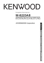
Figure 2:
Main station VSP-211-L principle diagram
2.1 Power
● An AC voltage appears between TP10/TP11 and TP12/TP13 when
the hand crank is activated. This voltage is rectified in D19 and D21,
providing DC power for two purposes:
-
Powering the amplifier
-
Creating a call signal
L
P8 and P9 together with D17 enables the use of the board with the old inductor.
● When a call is being made, the actual line will carry a generated
voltage. This voltage is fed through the active line via the
corresponding diode D11 and D12 to the amplifier.
● A permanent amplifier 24 VDC power can be supplied on the
connection block terminal 23 (+) and 24 (-).
L
To avoid noise problems, the 24 VDC power supply must be connected via a DC/
DC converter.
L
Note that the circuit boards can be used as spare parts for the older VSP units.
When using boards with inductors, remove jumpers from pins J6 and J7/J8 and
insert a jumper on pin J9 located to the left of the DIP switches.
2.2 Calling
● The station’s extension number is set by DIP switches P11 - P22.
This will activate the call signal generator in the called station and
provide power to the amplifier.
● The desired station is selected by a 12-way rotary switch.
When turning the hand crank, a voltage is supplied to the selected
line.
Содержание Vingtor Stentofon VSP 12-Way
Страница 1: ...Amplified BatterylessTelephone System VSP 12 Way A100K10873 TECHNICAL MANUAL...
Страница 17: ...17 VSP 12 Way Batteryless Telephone System Technical Manual A100K10873 8 2 VSP 122P...
Страница 18: ...18 A100K10873 VSP 12 Way Batteryless Telephone System Technical Manual 8 3 VSP 211 L 8 4 VSP 213 L...
Страница 19: ...19 VSP 12 Way Batteryless Telephone System Technical Manual A100K10873 8 5 VSP 223 L...