A100K11939
EA1400/EA1600 Installation & User Manual
9
3
Installation & Wiring
3.1. Unpacking
In addition to the amplifier, 3 pieces mounting plugs (for Audio Input, Audio Output and Fault Relay) are
included in the delivery.
3.2. Mounting
The amplifier is prepared for mounting in a rack with a standard width of 483 mm (19”) and 89 mm (2 HU -
3½”) vertical space.
Rack Temperature:
-15°C to +55°C
Zenitel recommends installing the amplifier in a ventilated technical instrument room with temperatures
b
18°C to +25°C
. This will also extend the life span of the system. If operated in higher
temperatures, the output RMS power may be degraded by <2dB after a period of continuous operation.
Humidity: <95% RH
Compass Safe Distance: >145 cm
AC power outlet with provision for grounding.
Forced cooling may be needed to avoid overheating of the rack.
WARNING
Failure to observe the above precautions could result in overheating that could damage the equipment or
create a fire hazard.
3.3. Cable Layout
Do not run the installation cable from microphone and alarm panels parallel to, or too near the
cables for loudspeakers or power cables.
The shields must be interconnected in junction boxes and grounded in the amplifier unit only. It is
good practice to have separate conductors for each type of signal cabling.
Two-conductor shielded cable is required for the microphone.
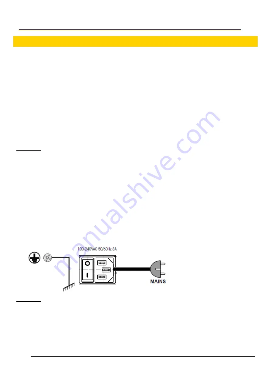
3.4. Mains Power and Grounding
WARNING
Do NOT connect AC power to the amplifier until all the necessary input and output connections have been
completed. Use a dedicated single-phase power input that adheres to the following recommendations:
100..240 VAC, 50-60 Hz, fused and capable of delivering a maximum of 8A .
The operating power should be wired and fused independently from all other inputs.
A warning tag should be attached to circuit-breaker-type fuses to prevent unauthorized manual
operation.


