background image


CHAPTER 4  - SYSTEM OPERATION 


Carl Zeiss 

Left Tool Area and Hardware Control Tools 

Lightsheet Z.1 


56 

000000-1790-528 

02/2013 

Light Sheet Illumination Settings 

The first choice to make regarding the 

Light Sheet illumination

 is given in the drop down menu and 

determines if the light sheet should only illuminate the sample from one side (

Single Side

) or if the light 

sheet is sequentially generated from both sides (

Dual Side

) (configuration dependent). The third mode is 

Dual Side when Experiment

. Here a single side illumination is kept during the setup of the experiment, 

hence when using the 

Continuous

 or 

Snap

 action buttons, which facilitates the setup of the imaging 

parameters. The dual side illumination is only activated when the 

Start Experiment

 button is pressed in 

the Multidimensional tool selection panel.  
If Single Side is chosen, the direction, 

Left

 or 

Right

, must be marked. This part of the panel is inactivated 

when the 

Dual Side

 illumination is selected.  

The 

Thickness

 of the Light Sheet at its center is displayed in µm.  

If 

Dual Side

 illumination is selected for each image (z-slice, time point) two frames are acquired, each 

with one illumination direction. The corresponding frames can be processed during image acquisition and 
combined into one frame when activating the 

Online Dual Side Fusion

 checkbox. The raw data will not 

be kept when 

Online Dual Side Fusion

 is selected, but only the resulting fused images. Or the raw data 

can later be fused using the 

Lightsheet Processing

 tools in the 

Processing 

tab.  


Pivot Scan Settings 

The 

Pivot Scan

 (configuration dependent) is used to move the light sheet within the focal plane of the 

detection optics in a wavelike motion. This results in a reduction of shadows which might otherwise be 

cast by optically dense structures within the sample. It can be used when activating the checkbox next to 

Pivot Scan


Acquisition area settings 

Information about the used number of 

Pixels


within the frame is given as well as the dimensions 
of the 

Image Size

  and the 

Pixel Size

  are 

displayed in 

µ

m. The dimensions will change when 

using the Zoom function described above. 

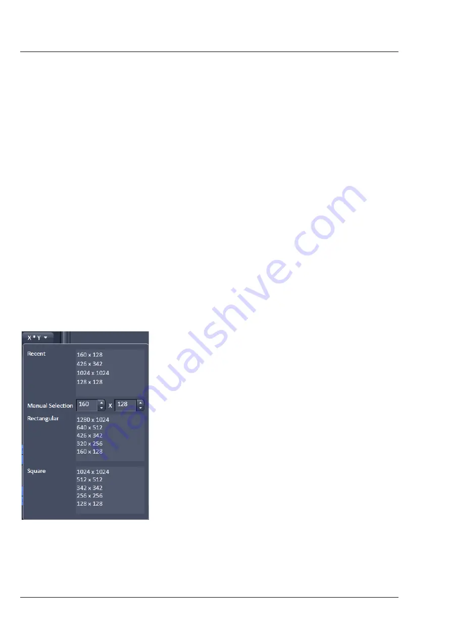
Frame 

Size

  and therefore the number of 

Pixels

  to be 

used  can be adjusted  by opening the drop down 
sub menu. Here you can choose either from a list 
of 

Rectangular

  or 

Square

  predefined crop 

settings. The last five used pixel numbers  from 
either list will appear in the 

Recent

 section of the 

sub menu. For individual adjustment you can type 

in the desired pixel amount for x and z next to 

Manual Selection

.  

When the 

Reset All

  button is pressed,  the full 

frame with all available pixels will be imaged. This 
button has no influence on the zoom settings.  


Fig. 77 

Frame Size  


Содержание Lightsheet Z.1

Страница 1: ...Lightsheet Z 1 Operating Manual February 2013 ZEN 2012 black edition ...

Страница 2: ...he specifications are subject to change the manual is not covered by an update service Unless expressly authorized forwarding and duplication of this document and the utilization and communication of its contents are not permitted Violations will entail an obligation to pay compensation All rights reserved in the event of granting of patents or registration of a utility model Issued by Carl Zeiss ...

Страница 3: ...ION Lightsheet Z 1 Carl Zeiss 02 2013 000000 1790 528 III Contents of this Manual Chapter 1 Hardware Chapter 2 Sample Preparation Chapter 3 Quick Guide Chapter 4 Software Operation Annex Lightsheet Z 1 Overview ...

Страница 4: ......

Страница 5: ...ions for the Detection Module Standard 23 3 3 Assembly of the Sample Chamber 24 3 3 1 Assembly of the Sample Chamber Windows 24 3 3 2 Assembly of the Sample Chamber Body and the Sample Chamber Dove Tail Slide 27 3 3 3 Insertion of the Drain Connector Luer Lock Connectors and Blind Plugs 29 3 3 4 Insertion of Accessories for Incubation 30 3 4 Removing and Inserting the Sample Chamber 31 3 5 Assembl...

Страница 6: ...Detection Optics 43 3 9 1 Removing and Inserting the Illumination Optics Unit 45 3 9 2 Removing and Inserting the Detection Optics Unit 46 3 10 Removing and Inserting the Reflector Turret for Emission Selection 47 3 11 Removing and Inserting the Reflector Turret for Laser Blocking Filter 49 4 INDEX 52 ...

Страница 7: ...water to which a small amount of cleaning agent has been added Do not use a solvent Dry off with a lint free cloth b To clean and disinfect the system cavity proceed as follows Switch the device off completely and pull the mains plug Make sure that no cleaning fluid is allowed to enter the system Take care not to touch the front lens of the illumination and detection optics units Remove these opti...

Страница 8: ...has been removed The parts may be laid in a disinfecting bath of 70 ethanol 1 hour and then thoroughly rinsed with distilled water The steel parts of the sample chamber may also be autoclaved as necessary Sealing rings hose connectors and blank plugs must be cleaned and disinfected as follows These parts may not be autoclaved First of all lay these parts in distilled water and then in a 70 ethanol...

Страница 9: ...cleaning procedure described above for special sterility requirements the front lens area of the detection modules can be cleaned several times with a lint free lens cloth or lens paper soaked in 100 ethanol Here again observe the general notes on cleaning the optics The clean microscope 1 1 Maintenance of the Liquid Cooling System If detection modules in your Lightsheet Z 1 are connected to a liq...

Страница 10: ...et Z 1 6 000000 1790 528 02 2013 2 ErgoDrive Operating Panel 1 Z axis control 2 Rotation button switches 6 to rotation drive 3 Mode button fine coarse 4 Axis button switches 6 to y axis drive 5 X axis control 6 Y axis Rotation control Fig 1 ErgoDrive operating panel ...

Страница 11: ...the movement of the specimen can be controlled as well The function to rotate around the center of the image Rotate around Center of image Fig 2 is only available through the software interface Even if chosen there the rotation controlled by the ErgoDrive operating panel will always rotate around the axis of the motor drive The steering elements are two vertical rotary controls for the x y and rot...

Страница 12: ...r pressing the Rotation button Fig 1 2 Clockwise clockwise rotation of the sample the angle is reduced in the software interface Counter clockwise counter clockwise rotation of the sample the angle is increased in the software interface Y axis control Upper rotary control Fig 1 6 after pressing Axis button Fig 1 4 Clockwise upward movement of the sample Counter clockwise downward movement of the s...

Страница 13: ...our convenience in accordance with the following disclaimer Carl Zeiss Microscopy GmbH hereinafter we hereby informs you that we will warrant the specified and agreed performance of the Lightsheet Z 1 system only if sample chambers are applied and used that either are delivered or explicitly approved by us The sample chamber design has been optimized to ensure the most established applications of ...

Страница 14: ...d misalignment The detection module should be gripped as close as possible to the contact ring A rotation guard plate Fig 3 7 is mounted on the contact ring of each detection module When mounting on both ports this must point toward the front side of the Lightsheet Z 1 It prevents rotation of the detection module and carries the laser protection notice Never remove the rotation guard plates of the...

Страница 15: ...2 transmission Cam2 3 Securing screw 4 Sensors 2 in sensor ring 5 Contact pins 2 on blind cap 6 Blind cap 7 Rotation guard plate with laser protection notice 8 Detection module varies 9 Contact ring of the detection module 10 Contact pins 2 on contact ring 11 Sensor disk 12 Sensor ring Fig 3 Mounting and dismounting the detection modules ...

Страница 16: ...ld remain on the system Hold the detection module firmly in one hand Loosen the securing screw with an Allen wrench Fig 3 3 on the sensor ring Fig 3 12 of the detector port Fig 3 1 and 2 Carefully pull away the detection module Fig 3 8 with contact ring Fig 3 9 using a slight tilting motion if necessary Cover the detector port Fig 3 1 and 2 on the main system module Lightsheet Z 1 and on the detec...

Страница 17: ...stem control are turned on and the operation system has booted start the software ZEN Configuration Tool This can be found either as a shortcut on your desktop or in this directory C ZEN HWT as Configuration Tool 2012 exe In the opening window press the Start configuring button Fig 5 1 Cable e g of the detection modules 2 Cable tie 3 Cable holder on system table Fig 4 Cable strain relief Fig 5 ZEN...

Страница 18: ...ules on a regular basis it can be helpful to create two databases one for each detection module type To do so copy the original database with a different name you find it in the directory C ZEN database and modify it with the Configuration Tool accordingly Make sure to always keep the original database Name both databases to easily identify them When ZEN is started open the Boot Status with the bl...

Страница 19: ... the process When the Cancel button is pressed the operation is aborted without saving any result This routine must be conducted before the Automatic or Manual Detector Alignment At the end of this process you be informed if the detector recognition had to perform any changes If so please restart the ZEN software before continuing 3 2 1 Adjustment Automatic Detector Alignment This adjustment is ne...

Страница 20: ...zard and first manually adjust the focus of the grating The necessary steps are described in section 3 2 3 Adjust the Grating Focus for the Automatic or Manual Detector Alignment Tool In Step 2 the movement of the correction plates is calibrated for both channels There is no interaction needed Press the Next button to continue after the task is done The following text is displayed Calibration of c...

Страница 21: ... Manual Detector Alignment tool see section 3 2 3 Adjust the Grating Focus for the Automatic or Manual Detector Alignment Tool 3 2 2 Adjustment Manual Detector Alignment This adjustment is necessary for one or two detection modules when you recognize a pixel shift between channels or when the zoom is not centered The Automatic Detector Alignment should always be performed first since it might alre...

Страница 22: ...us button in the Manual Detector Alignment window or in the Main tool tabs a new image will open with a live image of the grating Fig 11 When the grating is out of focus you need to refocus it for the relevant channel by performing the steps described in section 3 2 3 To check the focus zoom into the image using the Zoom function and look at the center cross within the square Fig 12 If the white p...

Страница 23: ...m1 or Cam 2 X and Cam 2 Y for Channel 2 Cam 2 to move the lines of the grating to overlay each other You can leave the Manual Detector Alignment by pressing the Close button at the bottom of the window 3 2 3 Adjust the Grating Focus for the Automatic or Manual Detector Alignment Tool During the Automatic Detector Alignment tool wizard and the Manual Detector Alignment tool a grating is brought int...

Страница 24: ...ench Fig 14 2 Monitor the live image of the grating while you turn the screw in any direction and find the position of the screw that results in the sharpest image Stop the continuous scan and close the front system door Set focus for Cam 2 Channel 2 Use the Light Path of the Manual Detector Alignment to direct light towards channel 2 and activate channel 2 Cam2 Press afterwards the Continuous but...

Страница 25: ... the grating while you turn the screw in any direction and find the position of the screw that results in the sharpest image Stop the continuous scan and place the black screw cap back on the system 1 Black screw cap 2 Allen wrench Fig 15 Position of the screw to adjust the focus of the grating for Cam 2 channel 2 ...

Страница 26: ... detection module is used first to the transmission port Cam2 approx 100 cm and then a third hose approx 200 cm leads back to the cooling unit The detection module cables are connected as follows CameraLink cables A and B are each plugged into the PC for system control The upper slots of the PC for system control are assigned to the detection module of the reflection port Cam1 CamLink A right and ...

Страница 27: ...s on the PC for system control the detection module from the reflection port Cam1 is connected to position FW 1 from the transmission port Cam2 to position FW 3 The trigger cable is plugged into the respective detection module and the three ends on the rear side of the main system module Lightsheet Z 1 to Camera 1 or Camera 2 as well as Camera 1 IN and Camera 1 OUT reflection port Cam1 or Camera 2...

Страница 28: ...clean circular 18 mm cover slip place cover slip into the empty sample chamber body window so it fits into the smallest groove Fig 18 2 you will need a fine forceps 3 Now place the O ring 18 mm O ring black into the corresponding groove Fig 18 3 Make sure not to disturb the positioning of the cover slip 4 Take the silver illumination adapter ring Fig 18 4 and lay it into the window making sure the...

Страница 29: ...ition with the forceps if necessary c Now place the O ring 18 mm O ring black into the corresponding groove on top of the cover slip Fig 19 5 d Take the silver retaining ring Fig 19 6 and place it inside the detection optics adapter 5x with the flat side with two notches facing you Using the circular pin side of the sample chamber window tool Fig 19 9 turn clockwise until finger tight e Placing th...

Страница 30: ...detection optic 5x 0 16 3 Detection optic adapter 5x 0 16 4 Cover slip 5 O ring 18mm O ring black 6 Retaining ring 7 8 For the detection optic 20x 1 0 40x 1 0 63x 1 0 7 Detection optic adapter 20x 1 0 40x 1 0 63x 1 0 8 O ring 15mm O ring black 9 Sample chamber window tool Fig 19 Assembly of sample chamber window for the detection optic ...

Страница 31: ...bottom of sample chamber body The sample chamber body Fig 21 3 can now be attached to the sample chamber dove tail slide Fig 21 1 Lay down the sample chamber dove tail slide with the two positioning pins facing upwards Fig 21 2 Take the sample chamber body and position it on to the sample chamber dove tail slide with the detection optic adapter window facing to the back relative to the sample cham...

Страница 32: ... Lightsheet Z 1 28 000000 1790 528 02 2013 1 Sample chamber dove tail slide 2 Positioning pins 3 Sample chamber body 4 Screw holes 5 Screws diameter M3 length 14 mm Fig 21 Assembly of the sample chamber body and the sample chamber dove tail slide ...

Страница 33: ...ids and or gasses For CO2 incubation the Luer Lock connector must be positioned at the upper right corner of the sample chamber Fig 22 2 For syringe based perfusion one can use any of the three lower screw holes The lower right corner screw hole is recommended for convenience Fig 22 4 For perfusion pump use the right side bottom screw hole for the perfusion input and either of the front lower corn...

Страница 34: ... sensor sleeve securely into the sample chamber body groove Fig 23 2 Place a cover on top of the sample chamber body Fig 24 3 This will minimize evaporation of medium or contamination of the sample chamber If CO2 module Lightsheet Z 1 is used configuration dependent chapter 2 7 2 the cover is recommended to maintain the CO2 gas concentrations Keep the opening as small as possible Use the 3 mm open...

Страница 35: ...the upper system cavity door Fig 25 3 If necessary remove the connections for the incubation device Fig 25 8 Loosen the screw Fig 25 4 on the sample chamber and pull the sample chamber out by the grip Fig 25 5 Inserting the sample chamber Take hold of the sample chamber by the lower grip Fig 25 5 and push the sample chamber Fig 25 6 into the guide rails Fig 25 7 Tighten the screw Fig 25 4 without ...

Страница 36: ...ary of choice Fig 26 6 2 The capillary should hold the sample and the appropriate plunger Fig 26 5 see as well the CHAPTER 2 SAMPLE PREPARATION in this manual The plungers that fit into capillary size 2 4 have to be used with corresponding Teflon tips that are already assembled onto the plungers Note that in addition 10x Teflon tips of each as well as matching Teflon tip tools are provided in the ...

Страница 37: ...in the Chamber Sample Holder Starter Kit Lightsheet Z 1 3 The sleeves are tube shaped with four slits at one end Insert the sleeves into the capillary sample holder stem Fig 26 2 so that the two slit endings point outwards and the non slit endings face toward the center 4 Take the clamp screw Fig 26 4 and position it onto the capillary sample stem holder turning clockwise three times 360 each turn...

Страница 38: ... the capillary stem holder with specimen into the sample disc holder until the ball bearing click position is felt 8 Before taking the capillary out chapter 2 6 retract the sample back inside the capillary glass via using plunger 9 For removal loosen the clamp screw and carefully pull the capillary through the stem sleeve by using the glass end nearest the color coded marking 10 Unscrew the clamp ...

Страница 39: ...ds Fig 29 3 Insert the sample holder gliding the sample holder disc along the guide rails Fig 29 2 It is placed correctly into a click position if the sample holder disc ball bearings lock into the three holes Notice the white line marking at the outer edge of the disc It can be used as a reference point for reorienting the sample holder disc once it was taken out Close the upper system cavity doo...

Страница 40: ...e to the Load position via the Specimen Navigator tool Fig 28 in the ZEN software see CHAPTER 4 SYSTEM OPERATION Open the upper system cavity door Fig 29 1 Take the sample holder out by gliding the sample holder disc along the guide rails Fig 30 1 Upper system cavity door 2 Guide rails 3 Capillary 4 Hole for disc ball bearings Fig 29 Inserting the Sample Holder Fig 30 Removing the Sample Holder ...

Страница 41: ...les and their connections to the system The second part deals with the registration of the incubation modules using specific software tools 3 7 1 Heating Components There are two different heating components available 1 Heating Block Sample Chamber Lightsheet Z 1 enables to heat the sample chamber from ambient temperature to 42 C 2 Peltierblock Sample Chamber Lightsheet Z 1 permits heating and coo...

Страница 42: ...to 1 5 min heating up to 1 0 min cooling The temperature inside the sample chamber is monitored by a temperature sensor Fig 23 1 Fig 32 3 For insertion of the temperature sensor in the sample chamber refer to section 3 3 4 Insertion of Accessories for Incubation The TempModule CZ LSFM contains a water based coolant reservoir For safety reasons Risk of electrical shock as a result of leakage the un...

Страница 43: ...needed follow the instructions from the PeCon manual After CO2 calibration the Lightsheet Z 1 system must be completely turned off before work with the system can continue Position the Luer Lock connector for CO2 incubation at the top right corner of the sample chamber Place a cover on top of the sample chamber body Fig 24 chapter 3 3 4 to maintain the CO2 gas concentrations The sterility of the C...

Страница 44: ...on with tubing 3 Temperature sensor with 4 pin connection cable 4 Blind plug 5 Luer Lock connector for perfusion pump in with tubing or alternatively for syringe based perfusion 6 Peltier Block S with 8 pin connector 7 Cooling liquid Silicon tube with male connector 8 Cooling liquid Silicon tube with male connector 9 Luer Lock connector for perfusion pump out with tubing 10 Drain connector with tu...

Страница 45: ... 1 and the PC for system control are turned on and the operation system has booted start the software ZEN Configuration Tool You find it either as a shortcut on your desktop or in this directory C ZEN HWT as Configuration Tool 2012 exe On the opening window press the Start configuring button Fig 33 On the Configuration tab Fig 34 you find an Incubation Components field with check boxes for CO2 Mod...

Страница 46: ...lectrical connection of the incubation components into the TempModule S1 Channel 1 4 Control Sensor We recommend to assign Channel 1 to the heating component Heatingblock Peltier Block and Channel 4 to the Heating Device Humidity if available Do not check the check boxes for external Sensor as well as an Humidity Sensor These components are not part of the Lightsheet Z 1 incubation modules Leave t...

Страница 47: ...ivate the incubation components by setting the Incubation switch to the OFF position Be aware that all incubation components will continue working with the in Incubator tool window specified parameters after ZEN has been shut down or stopped working This will keep your sample alive under precisely defined conditions even if ZEN stops unexpected during an experiment 3 9 Illumination and Detection O...

Страница 48: ... 312 217 217 87 87 63 1 0 382 382 198 198 138 138 55 55 Tabelle 2 Detection module PCO Edge Zoom Detection Optic 0 36x 0 7x 1 0x 2 5x x µm y 2 µm x µm y 2 µm x µm y µm x µm y µm 5 0 16 4157 5570 2138 2864 1497 2005 599 802 20 1 0 1039 1392 534 716 374 501 150 201 40 1 0 520 696 267 358 187 251 75 100 63 1 0 330 442 170 227 119 159 48 64 Tabelle 3 Detection module Standard 1 Typical values for Ligh...

Страница 49: ...can then be unscrewed by turning anticlockwise To insert the illumination optics proceed in the reverse order by screwing it clockwise into the unit until finger tight Finally the protective caps can be removed and the sample chamber inserted After the illumination optic has been exchanged the currently used optic must be registered in the ZEN software The necessary software interface can be found...

Страница 50: ...ved before re inserting the illumination optics unit and the sample chamber After the detection optic has been exchanged the currently used optic must be registered in the ZEN software The necessary software interface can be found in the Objectives tool window under the Maintain tab Each detection optic unit is labeled with an individual serial number It ensures that the specific calibration file ...

Страница 51: ... grip Fig 37 6 When inserting it is recommended that the reflector turret first of all be held by the short grip Fig 37 5 and inserted into the guide rail Fig 37 3 and then pushed in as far as it will go using the long pull rod Fig 37 6 Return the locking lever to its original position Finally close the system door The filters are not push and click filters and cannot be taken out as a whole The f...

Страница 52: ...eflective side of the filter must point towards the light source Put the ring on top of the filter and tighten it with the same tool without applying force The emission filters facing towards the side of the turret are part of the channel 1 Cam1 Emission Filter 1 light path the filters facing the top are part of channel 2 Cam2 Emission Filter 2 After replacing the reflector turret for emission sel...

Страница 53: ...ng and Inserting the Reflector Turret for Laser Blocking Filter To remove the reflector turret for laser blocking filter Fig 40 7 first open the upper rear system door Fig 40 4 Beneath this is an additional cover plate Fig 40 3 on which the knurled screws left and right Fig 40 1 can be loosened manually to lift off the cover by the black grip Fig 40 2 Turn the silver colored lever Fig 40 5 and pul...

Страница 54: ... Press the filter module against the upper spring clips until it engages firmly After replacing the reflector turret for laser blocking filter or individual filter cubes it must be registered in the database with the Configuration Tool software or modified in the ZEN software under the Maintain tab within the Filters tool window Fig 42 The position number on the turret is on the left side of the f...

Страница 55: ...CHAPTER 1 HARDWARE Lightsheet Z 1 User Interfaces Carl Zeiss 02 2013 000000 1790 528 51 Fig 41 Configuration Tool Filters tab Fig 42 ZEN software Maintain tab Filters tool window ...

Страница 56: ...7 Installation of Incubation Modules 37 Peltier Block S 38 Registration of modules 41 Temperature sensor 30 Tempmodule CZ LSFM 38 M Manual Detector Alignment 17 P Plunger reference number 33 R Reflector Turret for Emission Selection Database configuration 49 Exchange 47 Reflector Turret for Laser Blocking Filter Exchange 49 Push and click filter exchange 50 Rotate around Center of image 7 S Sample...

Страница 57: ... Chambers 18 2 3 2 Molding and Mounting Supports 20 2 3 3 Sample Holder 22 2 3 4 Gels and Polymers 23 2 3 5 Hydrogel Preparation 24 2 4 Fixation and Fixatives 25 2 5 Stains and Staining 25 2 5 1 Choosing a Fluorescent Label 26 2 6 Antifading Agents 26 2 7 Cleaning Labelling and Storing Samples 26 3 SPECIFIC EXAMPLES OF SAMPLE PREPARATION 28 3 1 Preparation of Fluorescent Beads 28 3 2 Preparation o...

Страница 58: ...ss Content Lightsheet Z 1 2 000000 1790 528 12 2012 4 TIPS TROUBLESHOOTING AND ADDITIONAL INFORMATION 37 4 1 Tips 37 4 2 Troubleshooting 37 4 3 Suggested Additional Sources of Information 40 4 4 References and Further Reading 41 5 INDEX 44 ...

Страница 59: ...t sheet heavily lipids lipid vesicles or dense collagen fiber arrays that scatter light strongly then the well defined shape and thickness of the sectioning light sheet degrades along the illumination axis In a second effect the detected image from a well illuminated sample might still be degraded by such a poorly transparent sample These effects can contribute independently to the final image qua...

Страница 60: ...lane illumination SPIM SPIM Jorand et al 2012 Planchon et al 2011 Zanacchi et al 2011 Verveer et al 2007 Plant Biology Live imaging of root growth Consecutive imaging of vertically growing root Arabidopsis thaliana Arabidopsis thaliana DSLM SPIM Maizel et al 2011 Sena et al 2011 Developmental Biology Imaging of developing organs Embryogenesis visualisation Zebrafish development Cell identity linea...

Страница 61: ...nce Large organism general biology Whole organism 3D reconstruction Whole organism 3D reconstruction Imaging copepod gut contents Whole organism 3D reconstruction Ormia ochracea Emblemasoma auditrix Drosophila melanogaster Calanus pacificus Thermocyclops consimilis LSP Ultramicroscope PLIF LSFM Huber et al 2001 Jahrling et al 2010 Jaffe et al 2009 Boistel et al 2011 ...

Страница 62: ...nd can increase further if immersion oil is needed The depth of the field of view is dependent on the type of objective lens and the sample properties and will deteriorate with the thickness of the sample Light Sheet based Fluorescence Microscopy LSFM utilizes illumination along an axis that is perpendicular to the detection axis Fig 1 C Moreover it usually allows sample rotation to record multipl...

Страница 63: ...s has several consequences for sample preparation First the refractive index of the mounting medium should be close to that of the sample buffer The mounting medium should not scatter the illumination or the detection light Second the mounting medium should not dissolve in water Third its diffusive properties should be close to those of water medium Fourth the medium should be non toxic for live s...

Страница 64: ...simplest way is to place the sample on a slide or a cuvette filled with medium underneath the objective Dodt et al 2007 alternatively the sample can be embedded in a gel rod that can be rotated In a horizontal configuration like the Lightsheet Z 1 the sample can be either embedded in a stiff gel Fig 3 A Huisken et al 2004 hooked and positioned in front of the objective Fig 3 B Engelbrecht et al 20...

Страница 65: ...f the LSFM optics geometry is that it allows so called Multiview imaging In this case the sample must be mounted to support the required positioning One approach used in Lightsheet Z 1 to support this experimental paradigm is to place the object in a gel rod that can be rotated Fig 3 A and E in front of the objective The hydrogel cylinder must be sufficiently stable to avoid movement during rotati...

Страница 66: ...capillaries for precise positioning translation and rotation of the cylinder shaped object for observation through the detection optics The used gel such as agarose behaves like mechanically stabilized water supporting the object It can be easily molded and the gel chosen should have an optical refraction index close to that of water The object can be any size as the gel can be molded accordingly ...

Страница 67: ...e image quality due to the optical properties of the material For smaller samples a capillary can be used as a sample embedding container There are several commercial companies that provide glass capillaries with specific Teflon plunger The Lightsheet Z 1 sample preparation kit comes with four sizes of capillaries and their specific plunger for this purpose Make sure you use the right capillary fo...

Страница 68: ...f an appropriate diameter Once the sample embedding container is prepared the sample preparation can begin The first step consists of preparing the supporting agent at a suitable concentration and temperature The gelling agent is usually a 0 7 to 1 solution of low melting agarose in water or PBS depending of the sample to be embedded fixed living sensitivity to osmotic pressure etc If the sample n...

Страница 69: ... to align the specimen in the most suitable way for imaging The orientation of the sample must then be optimized so that interesting details are facing the surface of the agarose cylinder with as little material as possible in the optical path One solution is to fill a syringe with agarose and allow it to cool until it solidifies The agarose is then pushed out of the syringe Fig 8 A and B A small ...

Страница 70: ...way of imaging an object is to simply take it as it is and place it in front of an objective In an LSFM this can be done by hanging the object in front of the objective where the axis of rotation and gravity are parallel This can be achieved using a simple hook made of glass stainless steel or plastic Fig 9 A This mounting technique can be used for large samples such as organs for example the brai...

Страница 71: ...ll require some initial adaptations to the sample holder The last important technique of holding samples to be mentioned in this section is to create a container that can hold the object in front of the objective lens This technique is particularly suitable for specimens that should not be embedded for example due to temperature physical constraints etc or that need to be constantly maintained in ...

Страница 72: ...epend on the size of the container walls and the inside chamber It is recommended to use a higher concentration of gelling agent to ensure the stability of the container We have used a 1ml syringe as a molding system and a concentration of 1 5 agarose for the container molding The stability is good and the degradation of the optical path is minimal Higher agarose concentrations may generate aberra...

Страница 73: ...e However the last two options have the disadvantage of partially obscuring the field of view This technique has been successfully used to image living cells Engelbrecht et al 2007 and cell clusters Pampaloni et al 2007 2 2 4 FEP Tubing More recently the availability of Fluorinated Ethylene Propylene FEP tube of different diameters has been successfully used for long term imaging of Zebrafish embr...

Страница 74: ...nce of the coverslips for the light sheet and the water filled space in between are a crucial measure in the optics calculation of the Lightsheet Z 1 system To ensure the functionality of the system these have to be maintained when a custom made chamber is designed Temperature control heating devices cooling devices Volume size of the sample buffer used cost drug treatment cost Fitting objective i...

Страница 75: ...d syringe 5 Sample chamber grip Fig 13 Removing and inserting the sample chamber The chamber has five entry points allowing the positioning of the objective the sample holder the light sheet and the observation by the user Heated chamber The chamber can be equipped optional with a Peltier Block that can be tuned according to needs or a Heatingblock For further details on the sample chamber handlin...

Страница 76: ... pumping and movement of the agarose rod used to embed the sample They can also be used to hang the sample by effectively using the plunger and syringe body as forceps The sample holder disc for syringes Fig 14 I and K provided should be used in this case Moreover they can be purchased sterile for single use applications In the case of Lightsheet Z 1 the sample kit is provided with four types of c...

Страница 77: ...3 1 5 mm size 4 2 15 mm B Specific plungers and Teflon tips for each capillary C Specific color coded sleeves to adapt each capillary to the sample holder F D Sample holder stem for capillaries clamp screw ejection tool E Sample holder disc for capillaries F Sample Holder diagram showing the capillary the stem and disc of the sample holder G and H Sample holder handling and insertion in the Lights...

Страница 78: ...d While in conventional imaging there is a suitable platform on which to place the glass slide or the chamber in LSFM the object must be held from above via the sample holder Depending on the size of the sample there are two different types of sample holders available sample holder for capillaries and syringes Fig 14 C F and I Always use the minimal cylinder diameter necessary for your specimen si...

Страница 79: ...is lower than that of normal agarose However to obtain the same strength a higher concentration needs to be used With a concentration of 1 w w the low melting point agarose has the same stability as a 0 5 agarose normal The refractive index at this concentration is still lower than that of normal agarose minimizing distortions when imaging In our laboratory we preferentially work with agarose as i...

Страница 80: ...in a water bath or on a heating plate It is very important especially for sensitive samples to ensure that the agarose is at 37 C before use Note Alternatively you can aliquot your agarose solution into 1 ml or 2 ml Eppendorf tubes for later use Label them and store them in a cool and dry place In this case each aliquot can be liquefied using a heating block 80 C 90 C then transferred to a heating...

Страница 81: ...he three dimensional reconstruction capability of the LSFM microscope the use of a fixative that does not destroy in vivo structure and organization is imperative It is important to remember that different specimens may require different fixation methods Testing and optimizing for each new sample type will ensure that the best balance between preservation and labeling is obtained Fixing and permea...

Страница 82: ...antifading agents so far However some applications may require the use of radical scavengers during long time imaging of GFP expressing samples as repeated exposure may lead to a regular increase of the free radical contents which might affect its behavior over time 2 7 Cleaning Labelling and Storing Samples One important point about samples is their handling In the case of LSFM all the samples ar...

Страница 83: ...e kept up to years In the case of LSFM the samples are imaged in a water environment and must be always kept wet even for long time storage This can be a challenge Usually we keep fixed samples in the fridge using a sample embedding container support and we refill the buffer tank from time to time However we never kept samples for more than a month under such conditions A longer storage possibilit...

Страница 84: ...P Agarose in deionised water Capillary Size 4 Blue 701910 BRAND GmbH Sonicator Heating block Vortex Method 1 Vortex the bead solution to make a homogeneous dispersion 2 Dilute a small volume of the bead dispersion in deionized or distilled water to a concentration 100x higher than the one desired for the specimen Depending on the size of the beads and the magnification required it is first necessa...

Страница 85: ...rose to have approximately 400 particles in the volume of interest Having too few of them less than 100 in the three dimensional image will give you no or poor processing results while too many of them more than 1000 might considerably increase processing time without a significantly improving the final results Moreover a gel with sufficient stiffness but minimal impact on the image has to be used...

Страница 86: ...move all medium and add the liquid agarose 3 Let the embryo fall to bottom of the Eppendorf tube Insert a capillary into the tube and suck the embryo into it by pulling out the thread or plunger like a syringe piston When sucking up the agarose make sure that initially the plunger is sticking out of the capillary within the liquid agarose to avoid air bubble formation Furthermore leave some space ...

Страница 87: ...pillary Size 4 Blue 701910 BRAND GmbH Heating block 90 C and 40 C Method 6 Choose a pupa Drosophila melanogaster Melt 1 LMP agarose aliquot 0 5 ml into a 1 5 ml Eppendorf tube Invert the tube to mix and allow agarose to cool to 40º C 7 To allow sample preparation the pupa must be submerged in agarose by pouring it directly on top of it in a large drop of molten low melting point agarose 8 The pupa...

Страница 88: ...ing block Method 1 Several agarose beakers are prepared as described in the enclosed sample section 2 Instead of pushing out the plunger to extract the agarose beaker the plunger is pulled in to the end of the syringe where it can be released leaving the beaker inside the syringe You need to make a long walled beaker to avoid inconvenient breakages and leakages that may be caused by the following ...

Страница 89: ... The incubation options for the Lighsheet Z 1 are described in another section of this manual CHAPTER 1 HARDWARE However cells must be mounted in a way that allows them to hang in front of the objective from above This protocol describes one way of imaging MDCK cells that naturally form cysts when grown in an extracellular matrix Equipment and reagents MDCK cells grown in an extracellular matrix M...

Страница 90: ... check viability and changes 3 6 Immunostaining and Preparation of MDCK Cell Cysts Immunofluorescence allows highlighting of specific proteins or structures using specific antibodies This protocol is used to perform immunofluorescence on cysts which are three dimensional cell structures that can be grown in extracellular matrix gel such as collagen Equipment and reagents 1 5 Low Melting Point LMP ...

Страница 91: ...12 The cysts can be stained at this stage with Hoechst to label the nuclei 13 The gel is pelleted and as much of the supernatant as possible is removed 14 The gel pellet is mixed with low melting point agarose mixed and pumped into a capillary The extracellular gel tends to clump once fixed and may stay as one piece when mounting Care should be taken to quickly but efficiently resuspend the gel 15...

Страница 92: ...rior to embedding Fig 19 B The syringe is prepared as previously described and filled with molten low melting point agarose 40 C The insect can then be inserted into the agarose cylinder and aligned using a needle or forceps Fig 19 C The insect can then be imaged Fig 19 D This technique can be applied to any insect or similar type of organism possessing an exoskeleton Depending on the animal part ...

Страница 93: ...match Light is refracted when it crosses the interface between two media of differing refractive indices RI Mismatching the refractive index of the objective immersion medium and mounting medium is one of the main causes of image degradation in microscopy Refractive index mismatch results in stretching compression of the z axis Also spherical aberration is worsened by axial spreading of the point ...

Страница 94: ...vel The specimen has to be fully immersed for good image quality Sample image is partially obscured or unevenly illuminated This can be a simple optical problem objectives or filters are dirty Clean them accordingly You can also check that all the components are well in place and aligned Your light sheet might not be properly aligned For Lightsheet Z 1 please realign the light sheet using the Ligh...

Страница 95: ...Other instruments that produce vibrations not completely dampened by the system table are in close proximity e g fridges centrifuges etc The stage is not properly fitted or damaged and prone to vibrations This includes the sample holder and the imaging chamber support Optical aberrations As in any optical technique the LSFM has advantages and disadvantages Some optical aberrations are more general...

Страница 96: ...Polish any cosmetic shop near you PBS local supplier Distilled water local supplier Ethanol local supplier Companies Sigma Aldrich http www sigmaaldrich com Applichem http www applichem de MP BIomedicals http www mpbio com Merck KGa http www merck de Materials Capillaries 100 µl color code Blue Brand GmbH Ref 7087 45 200 µl color code Red Brand GmbH Ref 7087 57 Companies Brand GmbH http www brand ...

Страница 97: ...itative fluorescence imaging of protein diffusion and interaction in living cells Nature biotechnology 29 9 pp 835 839 Dodt H U et al 2007 Ultramicroscopy three dimensional visualization of neuronal networks in the whole mouse brain Nature methods 4 4 pp 331 336 Ejsmont R K et al 2009 A toolkit for high throughput cross species gene engineering in Drosophila Nature methods Engelbrecht C J et al 20...

Страница 98: ...llumination microscopy Neuron 57 5 pp 661 672 Huber D Keller M Robert D 2001 3D light scanning macrography Journal of microscopy 203 2 pp 208 213 Huisken J et al 2004 Optical sectioning deep inside live embryos by selective plane illumination microscopy Science 305 5686 pp 1007 1009 Jährling N et al 2010 Three dimensional reconstruction and segmentation of intact Drosophila by ultramicroscopy Fron...

Страница 99: ...E G Stelzer E H K 2007 The third dimension bridges the gap between cell culture and live tissue Nature reviews Molecular cell biology 8 10 pp 839 845 Ritter J G et al 2008 High contrast single particle tracking by selective focal plane illumination microscopy Optics express 16 10 pp 7142 7152 Rubio Guivernau J L et al 2012 Wavelet based image fusion in multi view three dimensional microscopy Bioin...

Страница 100: ...nd Equipments Sample Chambers 18 Molding and Mounting Supports 20 Sample Holder 22 Gels and Polymers 23 Hydrogel Preparation 24 S Sample Holding 8 Sample Preparation Preparation of Fluorescent Beads 28 Preparation of a Medaka Fish Embryo 29 Preparation of a Fly Pupa 31 Preparation of a Plant Root 32 Samples Embedded 10 Hanging 14 Enclosed 15 Cleaning Labelling and Storing 26 Stains and Staining 25...

Страница 101: ...2 Adjustment of Z Stack Settings 39 3 3 Start Z Stack Experiment and evaluate Data 41 4 Z STACKS IN COMBINATION WITH TIME SERIES 45 4 1 Defining the Time Series 45 4 2 Start Z Stacks Experiment in Combination with Time Series and evaluate Data 48 5 SEE MORE FROM DIFFERENT ANGLES USING MULTIVIEW QUICK SETUP 52 5 1 Multiview Quick Setup 52 5 2 Start Multiview Experiment and evaluate Data 66 6 INDEX ...

Страница 102: ...pillary To locate the capillary or similar device which is holding the sample press the Locate Capillary button The white LED illumination is turned ON and the overview camera acquires a live image from the inside of the sample chamber Click Locate Capillary The live image from the inside of the sample chamber is displayed in the Center Screen Area ...

Страница 103: ...ured that there is no leakage within the sample chamber Please open the Camera Tool window to access the light intensity adjustment for the displayed image Click Camera Please adjust the light intensity by using the slider Light Intensity in the Camera Tool until details within the sample chamber become visible in the live image display Click Light Intensity The Zoom function is not available whil...

Страница 104: ...he sample holder Instead of using the Specimen Navigator you can also move and control the capillary containing the sample using the ErgoDrive operating panel Rotary controls X axis red control Y axis green control after pressing Axis button Or Rotary control after pressing Rotation button Z axis blue control Buttons The Rotations button changes the upper rotary control to move the rotation drive ...

Страница 105: ...1790 528 5 Click Y axis The capillary becomes now apparent in the displayed image Please bring the capillary in focus via the Z axis slider Click Z axis Moving the light grey cylinder representing the embedding medium into the light sheet graphic light blue can be used as a focus finding guide ...

Страница 106: ... the X direction Click X Axis The capillary is placed correctly when it is centered just above the detection optic lens Open the upper system cavity door and eject the agarose cylinder Please adjust the light intensity by using the slider Light Intensity in the Camera Tool until the specimen becomes visible in the live image display Click Light Intensity ...

Страница 107: ...790 528 7 Press the plunger of the capillary or syringe until the embedded specimen is roughly centered in front of the detection optics lens The Specimen is now properly centered in front of the detection optic lens Press the Stop button to end the image acquisition of the live image Click Stop ...

Страница 108: ...e sample within the sample chamber the Locate Sample button activates an infrared light source and shows a live transmitted light image in the Center Screen Area This image is taken using Channel 1 Cam1 Click Locate Sample Please fine adjust the X position of the capillary and bring the specimen into the center of the image Click X axis ...

Страница 109: ...Z 1 Locating Capillary and Sample Carl Zeiss 02 2013 000000 1790 528 9 Please use the Zoom slider to zoom into the image Click Zoom Please use the Light Intensity slider to increase the illumination on the sample Click Light Intensity ...

Страница 110: ...o access the lower tool tabs The distance between the Load Position and the y position for imaging is often quite large This results in very large numbers for the y coordinate which are not so convenient for use The current y position can be set to zero by pressing the Reset Y Reference button for your convenience Click Reset Y Reference ...

Страница 111: ...ng the sample to the desired point and pressing the Set Home Position button Click Set Home Position To return to this position click the Home Position button Use Rotate around Center of image to automatically correct the X and Y positions for rotational movement and keep the sample within the chosen field of view This can be helpful when the sample is not in the center of the embedding medium ...

Страница 112: ...8 02 2013 Please rotate the capillary until the specimens back side is in front of the detection optic lens Click Rotation axis Please fine adjust the X position of the capillary and bring the specimen into the center of the image Click X axis You can focus in Z through the specimen Click Z axis ...

Страница 113: ...ocating Capillary and Sample Carl Zeiss 02 2013 000000 1790 528 13 Please re focus in Z until you found the desired plane Click Z axis Press the Stop button to end the live image acquisition and turn off the infrared light source Click Stop ...

Страница 114: ...en is now properly orientated You can now proceed with adjusting your image settings The Zebrafish for illustrative purposes due to its larger size was shown for positioning in this chapter The following chapters demonstrate how to adjust image settings with Drosophila melanogaster as another possible model organism ...

Страница 115: ...f the Light Path Please click Acquisition to access all functions necessary for setting up and controlling light sheet fluorescent imaging and multidimensional data acquisition Click Acquisition The Light Path panel allows for new and or existing beam path configurations to be created and or edited and saved Click Light Path ...

Страница 116: ...iguration of the Light Path Lightsheet Z 1 16 000000 1790 528 02 2013 Pressing the Laser icon displays the laser control submenu Click Laser Lines Activate the laser s necessary for excitation by checking the corresponding boxes Click 488 ...

Страница 117: ...guration of the Light Path Carl Zeiss 02 2013 000000 1790 528 17 A dialog box appears for switching ON the selected laser s Click YES The Incubator button accesses all possible attached equipment Temperature C control and or Atmosphere control ...

Страница 118: ...QUICK GUIDE Carl Zeiss Configuration of the Light Path Lightsheet Z 1 18 000000 1790 528 02 2013 Detection Optics Display Select a suitable Laser Blocking Filter for blocking the laser light Click Laser Blocking ...

Страница 119: ...790 528 19 According to the chosen laser lines an appropriate Laser Blocking Filter can be selected Click LBF 405 488 561 The Beam Splitter button opens a drop down menu for choosing the Beam Splitter to direct the emission light towards the desired detector module Cam1 or Cam2 Click Beam splitter ...

Страница 120: ...GUIDE Carl Zeiss Configuration of the Light Path Lightsheet Z 1 20 000000 1790 528 02 2013 Click SBS LP 560 The activated Secondary Beam Splitter SBS will move into position and its name is displayed in the light path ...

Страница 121: ...Emission Filter 2 in front of Cam 2 will change as well in the light path Even though the specimen is only stained with one dye it is advisable to choose a Beam Splitter with an Emission Filter instead of only a Mirror for fluorescence detection Activate the imaging Channel by checking the box Cam 1 next to the detection module icon Make sure a suitable Emission Filter is selected for the specimen...

Страница 122: ... 1790 528 02 2013 Assign a specific color to the channel image by clicking on the detection module icon Channel Camera 1 A drop down menu opens for selecting a color or look up table LUT Click Channel Camera 1 Please select the green color for the dye shown in this presentation Click Green ...

Страница 123: ...onfiguration of the Light Path Carl Zeiss 02 2013 000000 1790 528 23 2 1 Adjust Acquisition Parameters In the Acquisition Mode tool tab acquisition parameters can be set Click Acquisition Mode Here the actual selected Bit Depth is displayed ...

Страница 124: ...Zoom during an acquisition session the light sheet alignment Lightsheet Auto Adjust in the Channel tool window needs to be re done The Single Side illumination is displayed by default from the Left direction irrespective of the configuration This setting corresponds to the standard configuration where the light sheet only illuminates the sample from one side If Single Side is chosen for Illuminati...

Страница 125: ...Light Sheet Thickness is displayed in µm The Pivot Scan configuration dependent is used to move the light sheet within the focal plane of the detection optics in a wavelike motion This results in a reduction of shadows which might otherwise be cast by optically dense structures within the sample Click Pivot Scan ...

Страница 126: ...settings for multidimensional acquisition but takes into account the imaging settings within the Acquisition Mode Tool and the Channels Tool Click Continuous After its activation the Continuous button changes into the Stop button Please adjust the Zoom to restrict the area you would like to image It is recommended to use a Zoom 0 7 this optimizes the image quality towards the edges Click Zoom ...

Страница 127: ...adjust Detectors and Illumination Settings The Channels tool provides definition of channels and tracks adjustments for Detectors Illumination settings as well as Display options Click Channels For each chosen laser line a slider with input box and arrows appears Here you can set the laser power in percentage of total output Click Laser power ...

Страница 128: ...ve in the histogram you can set the limit for the white value right This influences the contrast and brightness of the displayed image The detection module controls are marked as Cam1 or Cam2 and show up with a vertical line in the selected Channel color The Exposure Time ms is regulated with the slider input box and arrows Click Exposure Time ...

Страница 129: ...th Carl Zeiss 02 2013 000000 1790 528 29 To end Continuous acquisition press the Stop button Click Stop 2 3 Lightsheet Auto Adjust Wizard Please adjust the light sheet right before you start the acquisition by using the Lightsheet Auto Adjust wizard Click Auto Adjust ...

Страница 130: ...just wizard shows a live image of your sample on the left hand side The beam path and illumination settings are taken from the Channels Tool and Light Path Tool so no additional corrections are necessary The Specimen Navigator Tool is present on the right hand side A short description on what to do during this step is given at the bottom of the window ...

Страница 131: ... imaging conditions as possible Since the embedding medium is an optical element that will influence the formation of the light sheet for its adjustment the position and thickness of the embedding medium should be the same as during imaging When a position above or below your sample with only the embedding medium cylinder is in view press the Next button When you press Cancel you will leave the wi...

Страница 132: ...m the beam path so stray light from the activated laser can be seen as a live image on the left hand side Hence any bright or blocking structures like the sample holder or the sample are visible If this is the case the sample must be moved optimally in the y direction resulting in an evenly illuminated field of view Click Next You can follow the status of the adjustment on the progress bar ...

Страница 133: ...33 Click Finish The original position of your specimen will be restored after the wizard is finished The resulting settings from the light sheet alignment are automatically written into the input boxes Left and Right or only one of them if Single side illumination is chosen in the Acquisition Tool window ...

Страница 134: ...age using all active channels and tracks It thereby ignores the parameters activated in the multidimensional acquisition area but takes into account the imaging settings within the Acquisition Mode Tool and Channels Tool Click Snap The basic image settings are now optimized You can now proceed with a multidimensional image acquisition ...

Страница 135: ...0 1790 528 35 3 Quick Steps to a Z Stack 3 1 Defining the First Slice and the Last Slice Please activate the Z Stack checkbox in the Multidimensional acquisition field to acquire an image series in z Click Z Stack The Z Stack tool tab is only available when the Z Stack checkbox is ticked ...

Страница 136: ...sheet Z 1 36 000000 1790 528 02 2013 Click on the Arrow down button to access the lower tool tabs If the Z Stack tool bar is expanded the Z Stack control panel becomes available Click on the Hide button to hide the Right Tool Area and expand the Center Screen Area ...

Страница 137: ...cquisition using the currently active imaging parameters for defining the First Slice and the Last Slice within the Z Stack control panel Click Continuous When you reach the position within the specimen where you would like to start the stack press Set First and this position will be taken as the first position in the stack Click Set First ...

Страница 138: ...e end position within the stack is reached then press Set Last Click Set Last Be aware that you might need a wider range for the z stack which includes enough fiducials or other landmarks for the landmark alignment processing later To end the Continuous acquisition and save the specimen from unnecessary light exposure press the Stop button Click Stop ...

Страница 139: ...th of the stack in micrometers Press the Optimal button to set the number of slices to match the optimal Z interval This adjusts the number of Slices to keep within the Range set from marking Set First Set Last Pressing the Optimal button sets Interval to a value of half the optical slice thickness Two adjacent slices therefore have always a 50 overlap Click Optimal interval ...

Страница 140: ... up the Z Stack acquisition significantly When the Continuous Drive checkbox is ticked the Z Stack is performed by continuously moving the z drive The stack size is retained The z drive will move the distance of the optical slice thickness during one exposure time that is set within the Channels tool tab However the overlap of two adjacent frames resulting from the interval distance is kept in thi...

Страница 141: ...ick Steps to a Z Stack Carl Zeiss 02 2013 000000 1790 528 41 3 3 Start Z Stack Experiment and evaluate Data Click Start Experiment to begin recording the Z Stack Click Start Experiment You can follow the process by the displayed progress bar ...

Страница 142: ...rl Zeiss Quick Steps to a Z Stack Lightsheet Z 1 42 000000 1790 528 02 2013 The Gallery view displays images from the Z Stack Click Gallery Click on the Hide button to hide the Left Tool Area and expand the Center Screen Area ...

Страница 143: ...013 000000 1790 528 43 All the slices from the Z Stack are represented in the Gallery view side by side in a tiled fashion The maximum intensity projection shows an output image whose pixels contain the maximum value over all images in the stack at the particular pixel location ...

Страница 144: ...0000 1790 528 02 2013 You have successfully acquired a Z Stack You may now proceed with either 1 View tabs in the Center Screen Area Ortho View Cut View 3D View Image VisArt or 2 Processing tab in the Left Tool Area Maximum Intensity Projection as shown here Lightsheet processing ...

Страница 145: ...ies 4 1 Defining the Time Series Please activate in addition to the Z Stack the Time Series check box in the Multidimensional acquisition field to acquire an image series in Z in combination with a time series Click Time Series In the Time Series tool the parameters for the sequential image frame acquisition for a time series are defined Click Time Series ...

Страница 146: ...s in Combination with Time Series Lightsheet Z 1 46 000000 1790 528 02 2013 Click on the Arrow down button to access the lower tool tabs Click Arrow down If the Time Series tool bar is expanded the Time Series control panel becomes available ...

Страница 147: ... 528 47 To set up a time series acquisition first define the Duration it should acquire the images by using the slider or the text field or the arrow buttons Click Duration This selection box chooses the dimensions for setting the Duration either cycle msec milliseconds sec seconds min minutes h hours d days ...

Страница 148: ...90 528 02 2013 Click on the Hide button to hide the Right Tool Area and expand the Center Screen Area Click Hide 4 2 Start Z Stacks Experiment in Combination with Time Series and evaluate Data Click Start Experiment Click Start Experiment to begin recording the Z Stack in combination with a Time Series ...

Страница 149: ...1 Z Stacks in Combination with Time Series Carl Zeiss 02 2013 000000 1790 528 49 You can follow the process by the displayed progress bar The Gallery view displays images from the Z Stack in combination with the Time Series Click Gallery ...

Страница 150: ...the Left Tool Area and expand the Center Screen Area Click Hide The Gallery view displays images from the Z Stack within the Time Series The Gallery view in this example shows all slices from the Z Stack acquired at Time point number 7 The additional dimensions can be changed using the sliders and control blocks in the Dimensions View control block ...

Страница 151: ... Zeiss 02 2013 000000 1790 528 51 You successfully acquired a Z Stack over Time You may now proceed with either 1 View tabs in the Center Screen Area Ortho View Cut View 3D View Image VisArt or 2 Processing tab in the Left Tool Area Maximum Intensity Projection Lightsheet processing ...

Страница 152: ...ng Multiview Quick Setup 5 1 Multiview Quick Setup Activate the Multiview checkbox in the Multidimensional acquisition field to acquire diversely sized Z stacks using different Views A View is determined by the X Y and Alpha rotation motor position of the sample holder Click Multiview Along with a Multiview experiment a Z Stack is automatically activated and greyed out ...

Страница 153: ...ngles using Multiview Quick Setup Carl Zeiss 02 2013 000000 1790 528 53 Click on the Arrow down button to access the lower tool tabs Click Arrow down When the Multiview Setup tool tab is expanded the Multiview Setup control panel is available Click Multiview Setup ...

Страница 154: ... Lightsheet Z 1 54 000000 1790 528 02 2013 The Multiview Setup tool window is divided into three regions 1 The upper region is the organization region and provides access to the Quick Setup wizard 2 In the middle you find a list of created Views if already available and their control buttons ...

Страница 155: ...icated by the dot at the bottom of the outer circle When Views are already defined when starting Quick Setup you can choose to overwrite them or add the new Views to the list Note the Quick Setup will use all settings in the tool tab windows as they are for creating the views list They cannot be changed afterwards For example if you want to use the Continuous Drive for the Z Stacks that are create...

Страница 156: ...th a software interface that guides you through the process of setting up a multiview experiment This includes the positioning of the sample defining the necessary Z stacks Range Slices and Interval and the number of views Click Quick Setup The initial window for the Lightsheet Quick Setup wizard shows a live transmitted infrared light image of your sample on the left hand side ...

Страница 157: ...iview Quick Setup Carl Zeiss 02 2013 000000 1790 528 57 On the right hand side is the Image settings tool tab Here you have easy access to the Light Intensity slider for adjusting the infrared illumination The Specimen Navigator provides access to the focus and specimen position ...

Страница 158: ...t Angles using Multiview Quick Setup Lightsheet Z 1 58 000000 1790 528 02 2013 A short description of what to do during this step is given at the bottom of the window Move the Light Intensity slider to adjust the infrared illumination Click Light Intensity ...

Страница 159: ...Carl Zeiss 02 2013 000000 1790 528 59 If you have finished the image brightness and position adjustment please press Next Click Next To select the acquisition volume view x y a red rectangle is displayed in the live image window The red rectangle must be adjusted to completely surround the sample ...

Страница 160: ...heet Z 1 60 000000 1790 528 02 2013 To change its size grab it with the left mouse button on one of the corners and adjust the length of the adjacent sides Grab Corner To change its size grab it with the left mouse button on one of the corners and adjust the length of the adjacent sides Grab Corner ...

Страница 161: ...using Multiview Quick Setup Carl Zeiss 02 2013 000000 1790 528 61 Check by moving the Z drive to see if the red rectangle encircles the whole sample along its Z axis After pressing the Next button the sample is turned by 90 before proceeding to the next step Click Next ...

Страница 162: ...les using Multiview Quick Setup Lightsheet Z 1 62 000000 1790 528 02 2013 1 Re adjust the sample focus by using the Specimen Navigator tool tab if necessary It might be necessary to reposition the specimen using the X and Y drives as well Do not change the angle ...

Страница 163: ...ides and drag it to the wanted position Alternatively you can reposition the sample into the middle of the rectangle by using the Specimen Navigator Move the rectangle by grabbing the side Check by moving the Z drive to see if the red rectangle encircles the whole sample along its Z axis and continue with Next If you have finished Re focussing and selecting the acquisition volume view z y please p...

Страница 164: ...ck Setup Lightsheet Z 1 64 000000 1790 528 02 2013 This interface defines the number of views by entering the number of Rotations within the input box or by using the arrows Pressing the Optimal button sets Interval to a value of half the optical slice thickness Click Optimal Interval ...

Страница 165: ...ist For later Multiview Processing press the Sort Angles button that is present below the list of views Be aware that the Zoom setting will change when the volume defined in step 2 and 3 of the Multiview Quick Setup requires a larger field of view then with the Zoom set in the Acquisition tool window The Multiview Quick Setup uses the higher value of either the largest possible diagonal through th...

Страница 166: ...ng the Multiview Quick Setup the alignment of the light sheet must be checked and adapted Following the rule the light sheet adjustment is the last step before image acquisition 5 2 Start Multiview Experiment and evaluate Data Click Start Experiment to start acquiring the Multiview experiment Click Start Experiment You can follow the process by the displayed progress bar ...

Страница 167: ...s and corresponding slices from the Z Stacks Click Gallery All the Views and corresponding slices from the Z Stacks can be represented in the Gallery view side by side The Gallery view in this example shows all Views from the Experiment at Z Position 209 The additional dimensions can be selected with the sliders and control blocks in the Dimensions View control block ...

Страница 168: ...Lightsheet Z 1 68 000000 1790 528 02 2013 You successfully acquired a Multiview experiment You may now proceed with either 1 View tabs in the Center Screen Area Ortho View Cut View 3D View Image VisArt or 2 Processing tab in the Left Tool Area Maximum Intensity Projection Lightsheet processing ...

Страница 169: ...Acquisition Mode 23 B Beam Splitter 19 C Camera Tool 3 D Duration 47 E Emission filters 21 Exposure Time 28 G Gallery view 42 L Laser Blocking Filter 18 Light Intensity 3 6 Locate Capillary 2 Locate Sample 8 M Multidimensional acquisition 52 P Pivot Scan 25 R Rotary controls 4 Rotations 64 S Single Side 24 Slices 40 Snap 34 Specimen Navigator 4 T Thickness 25 ...

Страница 170: ......

Страница 171: ...2 INTRODUCTION TO THE SOFTWARE APPLICATION LAYOUT 13 2 1 Overview on the Screen Layout 13 2 2 Introduction to ZEN 14 2 3 Function Elements 16 2 4 Application Bar 18 2 5 Menu Bar 18 2 5 1 File 20 2 5 2 Maintain 20 2 5 2 1 Camera 21 2 5 2 2 Hardware Administrator 21 2 5 2 3 Test Grid 21 2 5 3 Help About 22 2 6 Main Toolbar 23 2 7 Status Bar 25 2 8 Left Tool Area 27 2 8 1 Tool Groups and Tools 29 2 8...

Страница 172: ... 2 7 Acquisition Parameter Acquisition Mode 53 3 2 8 Acquisition Parameter Channel 57 3 2 8 1 Defining Channels and Tracks 57 3 2 8 2 Defining Detector and Illumination Settings 61 3 2 8 3 Defining Display Options 64 3 2 9 Acquisition Parameter Incubator 65 3 2 10 Multidimensional Acquisition Z Stack 66 3 2 10 1 Performing a Z Stack Using First Last Mode 66 3 2 10 2 Performing a Z Stack Using Cent...

Страница 173: ...ion Fourier Transform 136 3 3 16 Processing Channel Alignment 137 3 3 17 Processing Lightsheet Processing 142 3 3 17 1 Dual Side Fusion 142 3 3 17 2 Multiview Processing 143 3 3 17 3 Online Multiview Processing 152 3 3 18 Processing Copy 153 3 3 19 Processing ICS 155 3 3 19 1 Remove Structure 156 3 3 19 2 ICS Correlation 157 3 3 19 3 Map Filter 158 3 3 20 Processing Adjust 159 3 3 20 1 Burn in Bri...

Страница 174: ...83 4 2 2D View 184 4 2 1 Dimensions 184 4 2 2 Display 188 4 2 3 Player 189 4 2 4 Graphics 190 4 2 5 Preview View 193 4 3 Split View 194 4 4 Gallery View 195 4 5 Ortho View 196 4 5 1 Ortho Select Function 197 4 5 2 Ortho Distance Function 198 4 6 Cut View 199 4 7 2 5 D View 200 4 8 3D View 3D VisArt 202 4 8 1 Shadow Projection 204 4 8 2 Transparency Render Mode 207 4 8 3 Maximum Mode 208 4 8 4 Surf...

Страница 175: ... ROI Additional View Type for Time Series 232 4 13 Information View 235 5 RIGHT TOOL AREA DATA MANAGEMENT AND STORAGE 236 5 1 General 236 5 2 Comments on Data Management 237 5 3 ZEN File Browser 239 5 3 1 Gallery View of the ZEN File Browser 240 5 3 2 Form View of the ZEN File Browser 243 5 3 3 Table View of the ZEN File Browser 244 5 4 Images and Documents Panel 246 5 5 Opening of Files via the O...

Страница 176: ...itch To switch on the system set the System switch Fig 1 2 to the ON position When set to ON the power remote switch labeled PC Fig 1 3 provides power to the PC for system control This allows use of the computer and ZEN software offline The storage and analysis PC has to be turned on separately and can be run independently of the Lightsheet Z 1 system To activate also the incubation components set...

Страница 177: ...utton or Enter The WINDOWS operating system desktop appears on the screen showing a number of icons ZEN icon Starts the ZEN software for operating the Lightsheet Z 1 system Configuration Tool icon The Configuration Tool permits alterations to the database of the Lightsheet Z 1 that is used by the ZEN software program This function should preferably be performed by trained personnel Now the complet...

Страница 178: ...ymbol Pressing the x cross symbol the Login ZEN dialog will be closed and the ZEN software will not be started The Login ZEN dialog allows you to boot the Software in different modes If the Boot Status is closed the options are Start System and Image Processing A third option Offline Demo becomes available Fig 5 once the Boot Status field is expanded by pressing the expansion symbol triangle You c...

Страница 179: ... Processing for data analysis only This mode ignores the hardware and activates only data handling and image processing functionality to analyze stored images Note that only those software tools will be displayed that are needed for processing and analysis of the data No hardware control tools will be shown Cancel to abort the booting process and to leave the dialog Note that the Cancel button wil...

Страница 180: ...change the database after having booted the system To do this choose from the File menu of the main tool area Login and the Login Zen dialog will appear Select the database by pressing Choose or Recent and the system restarts 1 2 Shutdown Procedure Do not switch the computer off until the ZEN software is closed and the Windows 7 operating system has completely shut down The program and or data fil...

Страница 181: ... System Carl Zeiss 02 2013 000000 1790 528 11 1 2 1 Exiting ZEN Software The Software can be shut down from File menu of the Main toolbar by selecting Exit Fig 10 or by pressing the Window Close button symbolized by a cross in the ZEN window Fig 10 Exit in the File menu ...

Страница 182: ... Press Ok after having made the desired changes for exiting the ZEN software 1 2 2 Switching the System Power Off ZEN software is exited successfully After having exited the ZEN software you may turn off the whole system with the following Shutdown procedure Shut down WINDOWS About 20 seconds after WINDOWS is shut down the computer turns off On the remote power switch turn off the System PC and In...

Страница 183: ...n Layout Carl Zeiss 02 2013 000000 1790 528 13 2 Introduction to the Software Application Layout 2 1 Overview on the Screen Layout Fig 13 ZEN Main Application window after Startup with empty image container Fig 14 ZEN Main Application window after Startup with several images loaded ...

Страница 184: ...ayed image can be displayed and or analyzed with many view options available through view tabs which can be found on the left side of the image According to the chosen view tab the required view controls appear in the View control blocks below each image File management and data handling tools are found in the Right Tool Area Color and brightness of the interface have been carefully adjusted to th...

Страница 185: ... shown by an identical grey header or click on the dock symbol at the right hand side of the blue or grey header A fourth option is to double click on the grey header at the original position in the tool group Another unique feature is the scalable ZEN interface This Workspace Zoom allows adjustment of the ZEN window size and fonts to the situational needs or your personal preferences Fig 16 Setti...

Страница 186: ...anation Tool group Tool closed or tool window opened Panel e g Zoom panel Field with a subset of tools of a tool window List box or selection box Selection of one of the displayed options via a mouse click The selected option is highlighted Open the box by clicking on the arrow button Input box with arrows spin box Input of text or numeric values via the keyboard or using the arrows ...

Страница 187: ...board Press the Shift or Ctrl key while clicking on the arrow button to change the numeric values in coarse or fine steps Button Selection performance of a function via mouse click Tab Selection of functions of a tab via mouse click e g Dimensions or Display tab Load Save Delete Buttons to load save or delete a configuration overlay set track setting etc New Save Close Buttons to open a new acquis...

Страница 188: ...rols for the Workspace Zoom including the Reset button for the Workspace Zoom and the button to re dock all free floating tools to the Left Tool Area Fig 17 Menu bar left side The menu functions are shown in the following menu overview see next page Workspace Zoom Moving the slider to left or right changes the display size of the Left Right Tool Area and the Center Screen Area Clicking the Reset b...

Страница 189: ... Open Opens an existing document in the active image container Save Saves the active document Save As Saves the selected image with entering new formats Export Exports the currently active document using varius image formats Open Containing Folder Opens the folder where the image file ist saved New File browser Opens a document containing a ZEN File Browser Acquisition New Acquisition Document Ope...

Страница 190: ... e g from Online with hardware started to Offline Image Processing or Demo mode without closing ZEN Spectra database starts the dialog used to handle previously recorded reference spectra This function is for LSM systems only See also section 5 Right Tool Area Data Management and Storage for image file handling 2 5 2 Maintain The Maintain menu from the menu bar contains additional modules to check...

Страница 191: ...the Pic button allows to set the white balance using the mouse cursor in the camera image The Set button will become active Press set to store new settings press Reset to return to the old settings Use the arrow buttons to adjust the color balance of the camera 2 5 2 2 Hardware Administrator The Hardware Administrator function is for servicing purposes and may only be used by authorized service pe...

Страница 192: ...ar Fig 22 Clicking About opens the About window Fig 23 The panel hosts important information about the software version number the license number and the available software modules The software version number follows the following rules Main Version number Service Pack number Hotfix number Build For example 7 1 3 352 reads Main Version 7 Service Pack 1 Hotfix 3 Built 352 Fig 22 Help menu Fig 23 Ab...

Страница 193: ...ading saving or deleting a workspace configuration These workspace configurations are saved settings that allow one to restore a pre defined layout of the whole ZEN application window including status size and position of tools and windows workspace zoom number of tool columns To save a workspace configuration click on the button The following dialog will appear The name of the workspace configura...

Страница 194: ...4 000000 1790 528 02 2013 To load a workspace configuration click on the button The following list box will appear Selecting one of the list entries will load the respective configuration To delete a workspace configuration click on the button The configuration to be deleted can be selected from a list ...

Страница 195: ...CPU usage free hard disc capacity free RAM capacity Position and pixel intensity Shows the intensity values of the existing channels for the current X Y and Z position of the mouse cursor in the image Frames per second FPS Shows the current frame rate in frames per second FPS Progress bar Shows the process of the running processes Either for rendering or processing actions or during acquisition of...

Страница 196: ...ayout Lightsheet Z 1 26 000000 1790 528 02 2013 System messages Next to the progress bar you find a green upside down exclamation mark and a white arrowhead When you click on the arrowhead a window opens in which the history of system messages is shown Fig 28 Fig 28 System messages ...

Страница 197: ...ls to operate the included tool Action buttons Action buttons are only available for the Acquisition Main tool to control the image acquisition process Tool groups Groups special tools e g Setup Manager or Acquisition Parameter Setup Manager These tools Laser and Light Path allow one to choose settings for illumination and detection Acquisition Parameter Tools continuously needed for all acquisiti...

Страница 198: ...ed by the check box the tool will appear in the multidimensional acquisition tool group The tool is then active and will be used after pressing the Start Experiment button The experiment type is represented graphically above the Start Experiment Tools tools window Used for setting up the system and software functions Experiment Manager This function allows selecting an Experiment Manager imaging c...

Страница 199: ... can be done by clicking the button The tools can also be undocked by simply dragging the header bar of the respective tool to the desired position To place a tool back into its home position click the button again or drag the tool back to the Left Tool Area or click on the grey place holder at the home position of the tool The last option is particularly useful if the screen gets too crowded and ...

Страница 200: ...vation of tools with respect to a multidimensional image acquisition using the tool window The tools for multidimensional image acquisition can be activated and selected by ticking the respective tick boxes in the selection panel Clicking on the check box next to the appropriate tool selects activates and displays the tool for multidimensional image acquisition Once selected by the check box the t...

Страница 201: ...tinuous starts the uninterrupted imaging procedure with the currently active imaging parameters Snap takes one image Start Experiment starts a multidimensional experiment Z Stack Time Series Multiview Stop stops imaging immediately The second context menu Fig 31 appears with a right mouse button click in the area of the tool groups Auto Close Mode means that the oldest open tool window will be clo...

Страница 202: ... the available image views Use the context menu for the Center Screen Area by clicking the background of a container the view of this area can be varied individually The Center Screen Area can be split into 1 2 or 3 container views So it is possible to show several images in parallel Images can be moved from one container to another using the drag and drop function 2 9 1 Overview for the Center Sc...

Страница 203: ...tions 4 2 2D View to 4 13 Information View Arrow down or arrow up button to hide or show the image control area Clicking on the arrow down button hides the image control area and increases the image view field of all containers in the vertical direction for a larger image display Clicking the arrow up button shows the image area in all containers once again Image view controls Activates one or mor...

Страница 204: ...ontainer If closing a container the included images will be moved automatically to another open container 2 9 2 Context Menu for the Center Screen Area Clicking the right mouse button on the background of the container opens the context menu for the Center Screen Area Fig 36 The following functions are available Display of the image tabs in the container header Text View Small Thumbnail View Large...

Страница 205: ... Tool Area by decreasing the center tool area Dragging the slider to the right side decreases the Right Tool Area up to the default size Save button Saves the selected imaged or changed image The Save as dialog appears New image document button Opens an empty image document in the active container Close button Closes the selected image The Close image dialog appears to close the image with or with...

Страница 206: ...cation Layout Lightsheet Z 1 36 000000 1790 528 02 2013 Big View button Shows images with the textual characters and a big image preview Save Status icon This icon appears in the image that is not saved yet Image information Displays the name type and file size of the image ...

Страница 207: ...ion Acquiring images with the Lightsheet Z 1 Processing Processing images and multidimensional multiview images taken with the Lightsheet Z 1 Maintain Setting imaging system and firmware parameters By pressing the arrow left symbol on the Expand tab at the right hand side border the left tool area will collapse to the left side The symbol changes to an arrow right symbol By pressing the latter the...

Страница 208: ...ensity slider in the Camera Tool window can be used The zoom function is not available during this process and remains deactivated The upper system cavity door can be open during this live image 3 1 2 Locate Sample To locate the sample within the sample chamber the Locate Sample button activates the infrared light source and a live transmitted light image is shown in the Center Screen Area This im...

Страница 209: ...g as the key or combination of keys are pressed To remain in the zoom mode press the Alt key at the right side of the keyboard also The zoom will remain until the Ctrl key is pressed again To move the sample holder in the x y or z direction you can either place the mouse over the according colored line in the graphic hold it with the left mouse button and drag it to the required position or you ca...

Страница 210: ... This results in high numbers for the y coordinate which are not easy to handle The current y position is set to zero when you press the Reset Y Reference button This will not affect the coordinates in the Multiview Setup tool window see section 3 2 12 Multidimensional Acquisition Multiview Setup Here the y axis parameters will retain their original naming and need no changing 3 1 4 Incubator Tool...

Страница 211: ...anel allows defining CO2 concentration via the input boxes Either type in the numbers or use the arrows to set the parameters Actual values will be displayed on the right 3 2 Acquisition Tab If Acquisition is selected the Acquisition panel becomes available Fig 45 Acquisition contains all functions of the system that are needed to set up and control light sheet fluorescent imaging and multidimensi...

Страница 212: ...f the experiment list box Fig 49 Afterwards press the disc icon to save the new configuration or press the cross icon to abort the process The process is similar when renaming an experiment by pressing Rename or using the Save As option After typing the wanted name the changes can be either saved or the process can be aborted To save changes done in the tool tabs to a previously defined experiment...

Страница 213: ...ous produce images from all active channels and tracks thereby ignoring the settings for multidimensional acquisition but taking into account the selected imaging settings The last frame taken will stay in the image window To disrupt Continuous acquisition the Stop button has to be pressed which is what the Continuous button changes into after its activation Fig 51 The stop of the continuous image...

Страница 214: ...Multidimensional acquisition field Fig 53 the multidimensionality can be defined by checking the corresponding boxes The following dimensions are available Z Stack Acquisition of an image series in z Time series Acquisition of an image series in time Multiview Acquisition of diversely sized Z Stacks at different Views A View is determined by the x y and alpha rotation motor position of the sample ...

Страница 215: ...uisition taking into account all activated functions The progress of the experiment in regards to which image the system currently acquires will be shown updated to the right of the functions if available Fig 55 When Streaming is activated in the Streaming tool window under Maintain see section 3 4 4 Maintain Streaming pressing Start Experiment will open a Windows explorer window Here the file nam...

Страница 216: ... the laser On or Off To switch a laser on select On from the respective pull down menu For each laser the properties are displayed if the Laser Properties window is opened After turning the Laser on the Status will change from connected to Warming up to Ready Upon exiting the Software the Laser Off panel will be displayed if the lasers off on exit checkbox in the Hardware tab of Systems Options fo...

Страница 217: ...th The Light Path panel allows new existing light path configurations to be created edited and saved Click on the Light Path tab to open the Light Path configuration panel Fig 57 Click on any other tab to leave the panel The Light Path panel is divided into the Track definition field Beam path configuration field Fig 57 Light Path configuration panel ...

Страница 218: ...rame Fast Frame and every Z Stack Fig 59 Frame will image every frame with all available tracks before moving to the next slice of a defined Z Stack Up to 4 tracks can be imaged The Continuous Drive in the Z Stack tool window is deactivated In Fast Frame mode up to 2 tracks can be defined switching of hardware components that require mechanical movement like filter changes is prevented and hence t...

Страница 219: ...rs the arrows or typing into the display field 3 2 5 4 Incubator You have access to incubator functions by pressing the Incubator button This opens the expansion submenu for access to the possible attached equipment Temperature C control Atmosphere control The Temperature o C panel allows you to control up to 2 independent heating channels that are linked to certain devices Peltierblock Sample Cha...

Страница 220: ...g 65 There are six positions available in the turret To choose one click on it The turret will move to the correct position and the filter and its name will be shown in the light path 3 2 5 7 Emission Selection Filter Selection The Emission Selection Filter button opens a drop down menu in which you can choose the Beam Splitter to direct the emission light towards the desired detection module Cam1...

Страница 221: ...ate a channel for imaging check the check box next to the detection module icon either Cam 1 or Cam 2 To deactivate the channel uncheck this box Fig 67 To assign a specific color to the image of a channel click onto the detection module icon and select a color or look up table LUT from the drop down menu Fig 68 Fig 67 Detection module icon Fig 68 Look up table to choose Channel display color ...

Страница 222: ...n of keys are pressed To remain in the zoom mode press the right Alt key The zoom will remain until the Ctrl key is pressed again To move the sample holder in x y or z direction you can either place the mouse over the according colored line in the graphic hold it with the left mouse button and drag it into the required position or you can use the sliders and spin boxes for each axis below the grap...

Страница 223: ...ant to return to during the course of imaging by pressing the Set Home Position button after putting the sample to the desired spot To return to this position you click the Home Position button The distance between the Load Position and the y position for imaging is often quite large This results in high numbers for the y coordinate which are not easy to handle The current y position is set to zer...

Страница 224: ...se the arrows This zoom is realized with hardware zoom optics within the system When using the Zoom the number of pixels stays unchanged But the size of the total area imaged Image Size and the area represented by a pixel Pixel Size will change accordingly You can look at the image and pixel dimensions in µm in the Acquisition Area The Zoom numbers are displayed in red when set to values from 0 36...

Страница 225: ... the image field Fig 74 To return to the ideal light sheet thickness ratio use the Zoom slider in the Acquisition Mode tool window Be aware that the Zoom and the Center Thickness settings are influencing the dimensions of the light sheet overall The ratio or the thickness in the center of the light sheet and at its border should be ideally 1 2 for the used frame The Select by Region button opens a...

Страница 226: ...ombined into one frame when activating the Online Dual Side Fusion checkbox The raw data will not be kept when Online Dual Side Fusion is selected but only the resulting fused images Or the raw data can later be fused using the Lightsheet Processing tools in the Processing tab Pivot Scan Settings The Pivot Scan configuration dependent is used to move the light sheet within the focal plane of the d...

Страница 227: ...nels Cam1 or Cam2 for that track are indicated Each track that is selected by mouse click is highlighted and is displayed in the Track Configuration display area which allows for individual settings for each track Fig 78 A track will only be active when the Continuous Snap or Start Experiment button is pressed if the track check box is ticked Changes in the selection of the tracks in the Channel t...

Страница 228: ...y pressing the upwards pointing open arrow the highlighted track will move one position up in the displayed track array Fig 80 Likewise by pressing the downwards pointing open arrow it will move one position down The arrows are only active if an upward or download movement is possible You can add up to 4 tracks by pressing the button You can delete tracks by highlighting them and pressing the tras...

Страница 229: ...ll saved track configurations are displayed To search for a track configuration type in its name or part of its name into the Search field and only those track configurations will be listed that contain the typed in string of letters To delete a track configuration press the Delete button symbolized by the trash can icon This opens the Delete configuration window Fig 83 Select the configuration fr...

Страница 230: ...ack Fig 86 If a highlighted track is saved with a certain name or a predefined track with a name is loaded into a highlighted track the new name will appear in the Tracks designation box automatically Track designation in the Light Path tool will automatically be updated Fig 87 The total set of parameters for one or multiple tracks can be stored as an acquisition configuration using the save optio...

Страница 231: ...ctive input box is accessible while the other one is inactive This way only the chosen illumination side can be changed The numbers of the input boxes correspond to the Light sheet adjustment settings for the left and for the right illumination side They can be changed manually For proper adjustment the Auto Adjust wizard can be used For each Track this alignment must be done separately The light ...

Страница 232: ...uld be used during this step since the conditions for the light sheet adjustment should be as close to the imaging conditions as possible Since the embedding medium is an optical element that will influence the formation of the light sheet for its adjustment the position and thickness of the embedding medium should be the same as during imaging That is easiest to achieve when only the y position i...

Страница 233: ...iew To proceed press the Next button The window of the Auto Adjust wizard is now minimized and a smaller control panel remains Fig 91 A progress bar shows the progress of the light sheet alignment There is no interaction needed A short text describes the process The Light sheet alignment for the laserline of this channel is in progress Please wait When the light sheet adjustment is finished it is ...

Страница 234: ... artifacts in some cases these critical exposure times are displayed in yellow When a detection module with liquid cooling is used the working temperature is displayed below the Exposure Time 3 2 8 3 Defining Display Options By pressing the black arrow on white background next to Display at the bottom part of the Channel Tool window you access two checkboxes which influence the display of your ima...

Страница 235: ...in the Incubator tool window or turn off the Incubation via the remote control You will have access depending upon the attached equipment to Temperature C control Atmosphere control To have access to the respective controls expand the fields by pressing the triangles Fig 93 The Temperature o C panel allows you to control up to 2 independent heating channels that are linked to certain devices Pelti...

Страница 236: ...focus onto the specimen While imaging change the focus using the focus drive of the Ergo Drive control panel or the z drive control within the Specimen Navigator Tool tab When you reach the position within the specimen where you would like to start the stack press Set First and this position will be taken as the first position in the stack Move the focus in the other direction until the end positi...

Страница 237: ...ained The z drive will move the distance of the optical slice thickness during one exposure time that is set in the Channels tool tab However the overlap of two adjacent frames resulting from the interval distance is kept in this mode When the Continuous Drive is deactivated each image is taken after the z drive has come to a stop After the frame is imaged the interval distance is travelled before...

Страница 238: ...option to switch between Keep Interval and Keep Slice If Keep Interval is checked the number of slices is adjusted to a new Range defined pressing Set First or Set Last Likewise when Keep Slice is checked the value for the Interval between the slices is adjusted to a new Range defined by pressing Set First or Set Last The Position µm input box indicates the current position of the focus The number...

Страница 239: ...acquisition of image frames as time series are defined When time series are acquired with the Lightsheet Z 1 a master file is created with the following appearance Name czi e g FishEmbryogenesis czi For each time point a separate file is additionally formed in the same folder with the nomenclature Name time point czi e g FishEmbryogensis 221 czi To set up a time series acquisition first you define...

Страница 240: ...and Cancel if it takes too long After the Validate Speed process is finished information is given on how long the experiment will last Fig 98 If a number of cycles is chosen for the experiment the text on the left reads The Experiment runs for h when a duration is chosen it shows The Experiment runs for cycles On the right hand side the duration for one time point is shown There are different adva...

Страница 241: ...dicated by a blue marker in the time series see also section 3 2 11 2 Marker You can load a predefined timer configuration from the Interval Time field by pressing the Load button symbolized by the folder icon Fig 100 All saved timer will be listed in the Load configuration panel Fig 101 Select the appropriate one by highlighting it in the Recent section which lists the recently used timer configu...

Страница 242: ...11 2 Marker Expand the Marker field by clicking the triangle Fig 105 The Marker functionality provides the possibility to indicate the start or end of an external process in the data of the image series You can edit a description of that marker in the Description box of the Marker which will be visible in the image data using the Mean ROI functionality or the image gallery display mode By clicking...

Страница 243: ...ved marker configurations are displayed To search for a marker configuration type in its name or part of its name into the Search field and only those marker configurations will be listed that contain the typed in string of letters To delete a marker configuration press the Delete button symbolized by the trash can icon This opens the Delete configuration window Fig 108 Select the marker configura...

Страница 244: ...g meaning red manually set marker with time indication and comments blue automatically set marker with change of interval 3 2 11 3 Start Expand the Start field by clicking the triangle Fig 111 In the Mode drop down menu Fig 112 you can select the way the acquisition is triggered You have the choice between Manual and Time If Manual is selected the acquisition of a time series is started using the ...

Страница 245: ...errupts the acquisition after the defined computer time has been reached A Time Series is finished when the end Time is reached If the entered number of Cycles has been processed the Time Series is finished before the end Time If the number of cycles has not yet been processed until the end Time the Time Series is also finished The end time for the Time Series can be changed online If a time serie...

Страница 246: ...This button must not be used during an experiment in progress You can load a predefined MultiViewList Fig 118 by pressing the Load button symbolized by the folder icon This opens a Windows explorer window in which you can open the folder and select the MultiViewList file mvl to open Its name will appear in the Input box To save a list of Views press the save button symbolized by the disc This open...

Страница 247: ...l and the number of views The Views created with the Quick Setup can be added to an already existing list or replace the old entries Be aware that the Quick Setup is a tool to facilitate the creation of a multiview experiment but the resulting Z Stacks might have a wider range then absolutely necessary to image the specimen If data size is an issue in your experiment or time considerations it can ...

Страница 248: ...umbered 1 to 4 and describes which task needs to be done by the user The lower section holds the buttons Previous to go one step back Next to proceed to the next step and Cancel to end the process without result The Previous button is inactive in the first step and the Next button is replaced by the Finish button in the last step Step 1 Adjust image brightness and position Position your sample wit...

Страница 249: ...pletely To move the whole rectangle grab it by holding the left mouse button on one of the sides and dragging it to the wanted position To change its size grab it with the left mouse button on one of the corners and adjust the length of the adjacent sides Check by moving the z drive if the red rectangle encircles the whole area of interest along its z axis After pressing the Next button the sample...

Страница 250: ...y Adjust the focus for the sample with the Specimen Navigator tool tab or the Ergo Drive control panel Fig 122 It might be necessary to reposition the specimen with the x and y drive as well Do not change the angle at this step As in Step 2 the red rectangle must surround the region of interest again adjust position and size of the rectangle Fig 122 Multiview Quick Setup Step 3 ...

Страница 251: ... step 2 and 3 of the Multiview Quick Setup requires a larger field of view then with the Zoom set in the Acquisition tool window The Multiview Quick Setup uses the higher value of either the largest possible diagonal through the volume or the length of the y axis as a reference to determine the needed field of view hence the Zoom When the Zoom setting is changed during the Multiview Quick Setup th...

Страница 252: ...isplayed Fig 125 The scrollbar must be used to have access to all functions The Processing tool provides a number of methods for image processing and analysis using mathematical operators and algorithms which include Maximum Intensity projection Stitch Color coded projection PALM Image calculator Particle Tracking Average Structured Illumination Filter Channel Alignment Linear Unmixing Lightsheet ...

Страница 253: ...tools the PALM image based on the table has to be converted to a true image Such a function is available as a sub function in the PALM Processing tool Calculated high resolution PALM images are stored as czi format however they are based on a table and only few functions can be used with those images If you want to have access to other functions PALM images have to be first converted to true image...

Страница 254: ...ect the first image to be loaded in the image container and press the Select button for Input image Then select the second image to be loaded in the image container and press the Select button for Input image 2 Note that once an image is loaded by pressing Select it cannot be unloaded but only be replaced by another one This holds also true if the Processing tool is changed the previous loaded ima...

Страница 255: ...nd the field remains empty Only those functions will be displayed that match the dimensions of the image parameters and that can be applied to the loaded image Once an Input image is selected the Preview panel becomes available at the bottom field It shows the Input image or Input Image and Input Image 2 which can be selected by pressing the respective thumbnail on the left and the Preview image o...

Страница 256: ...ity Projection Processing tool select it from the list in the Processing main tab Click on the triangle buttons to show or hide the Method Parameters and Preview panels of the function Select the Input Image with the Select button and choose the dimension along which you want to generate a maximum intensity projection from the Coordinate pull down menu z time channel in the Settings panel Clicking...

Страница 257: ...projection Processing tool select it from the list in the Processing main tab Click on the triangle buttons to show or hide the Method Parameters and Preview panels of the function Select the Input Image with the Select button and choose the dimension along which you want to generate a color coded projection from the pull down menu z or time in the Method Parameters panel Select one of the two col...

Страница 258: ...ge Display as Input Image and Input Image 2 The Output Image is automatically fed into a new image document A specific input channel from a multi channel image or series can be selected using the pull down menus next to the Select buttons The number in the First image display box which can be edited reduces the Input 2 Image series to the selected first frames of a time series This can be used to ...

Страница 259: ... to Intensity range 0 1 should be marked This normalizes the image intensity for all images to values between 0 and 1 All actions performed in the Image Calculator have immediate effect on the previews After pressing the Apply button on the top of the Processing main tab a new image document with the resulting image is created A good example application for the Image Calculator is offsetting norma...

Страница 260: ... Select how many pixels you want to bin in x direction y direction and time points by setting the respective values in the X Average Pixels Y Average Pixels Z Average Pixels and Time Average Pixels input boxes which can be opened by clicking on the arrows Note that Z Average Pixels and Time Average Pixels are only available for Z Stacks and time series You can either enter a value or use the slide...

Страница 261: ...se the filter of your choice from the Type pull down Median Smooth Sharpen Band and Gradient Select the channels you want to process with the All Ch T1 or Ch T2 buttons Once a filter has been selected from the type drop down menu filter specific settings are available Median Filter With the median filter the gray value of each center pixel is replaced with the median value of the neighboring pixel...

Страница 262: ... in pixels set by the Strength slider It has an analogous effect as the kernel size Fig 136 If a dimension should be processed by this tool the respective X Y Z and Channels check boxes must be ticked The modified pixel now is the center pixel of the filter matrix Image noise will be reduced by the application of the low pass filter Sharp edges of regions will blur Local maxima will be flattened T...

Страница 263: ...f a dimension should be processed by this tool the respective X Y Z and Channels check boxes must be ticked Gradient Filter The Gradient Filter visualizes the direction and rate of brightness changes from one pixel to the other It illustrates if brightness changes smoothly or abruptly in the image Fig 139 The gradient filter can be used for all dimensions present in one dataset You can select it i...

Страница 264: ...ictly pixel by pixel image analysis procedure Experimentally fluorescence spectra of mono labeled samples are acquired and stored in the Spectra Database as an external reference Then a multi channel image or Lambda stack available only in LSM imaging mode from the multi labeled sample is acquired Finally the individual components are mathematically extracted using the information from the referen...

Страница 265: ...a stacks only available in LSM imaging modes or multi channel images can be loaded In the Linear unmixing panel Fig 141 the number of spectrally distinguishable fluorescent components within the imaged sample can be selected from the Components selection box The number of extractable components cannot be higher than the number of acquired channels The ZEN software is limited to a maximum of 10 com...

Страница 266: ...esent the difference between the acquired spectral data and the fitted linear combination of the reference spectra In essence the residual value is the biggest remaining residual from the least square fit routine The residuals are a general measure for how good the fit of the algorithm has performed The higher the intensity in this additional channel the worse is the fit of the spectra to the data...

Страница 267: ...hannels with statistical confidence This option displays an additional channel per unmixed component which shows the relative statistical error in each unmixed component channel This statistical uncertainty of the pixel intensity in the unmixed channel is calculated based on the Poisson noise from the acquired input channels the bandwidth and position and the quality of the reference spectra The d...

Страница 268: ...lapping signals this method will yield poor results Avoid saturation of fluorescence signal in the data set to be unmixed Saturation will generate a high signal in the residual channel To get the best unmixing results define an extra background channel if possible Reference Spectra used for Linear unmixing of the Lambda stacks processed in the Unmixing View are stored with the resulting image and ...

Страница 269: ...concentrations in physiological experiments To open the Ion Concentration tools click Ion concentration Fig 145 The two buttons select the active image in the Image Display as Input Image and Input Image 2 for background subtraction The name of the automatically generated Output Image is shown under the name of the Input Images In the Preview panel at the bottom of the Ion concentration tool windo...

Страница 270: ...etric the calibration method and if the calibration is carried out in vitro situ Ch 1 and 2 select the channels from Input Image 1 From these pull downs the following combinations of parameters can be chosen Dye single wavelength vs ratiometric Available methods for single wavelength Titration or equation both in vitro and in situ calibration Available methods for ratiometric dyes Ratio titration ...

Страница 271: ... 3 8 1 Single Wavelength Dyes Offline Calibration Subtract background autofluorescence image from raw images to obtain better raw data to start with Fig 148 Perform equation or titration calibration compare F with a calibration curve titration calibration or put F values in calibration formula Fig 148 Ion concentration panel ...

Страница 272: ... autofluorescence over time Calculate absolute ion concentrations pixel by pixel via titration calibration known ion concentrations applied to the cells in situ or in solutions in vitro or equation calibration where possible Fura 2 Indo SNARF Calculation of R eliminates artifacts and uncertainties caused by inhomogeneous dye distribution photobleaching may be applied with moving cells Ratiometric ...

Страница 273: ...t background autofluorescence images from raw images to obtain Rkorr F1 F1Background F2 F2Background when calibration reference is not obtained with the experimental sample in situ Calculate ratio R Perform equation or titration calibration compare R with a calibration curve titration calibration or put R values in calibration formula Fig 150 Ion concentration panel ...

Страница 274: ... g saturated with Ca2 Fmin2 and Fmax2 are the minimum and maximum fluorescence intensities at wavelength 2 Rmin Rmax Fmin2 and Fmax2 may be determined in the cells under investigation in situ or in solutions in vitro Calibration parameters may be saved and reloaded cal Options for Calibration Image Selection Equation or Titration Calibration Click into image window Select source channel s Optional...

Страница 275: ...maging mode or temporal correlation of an image or image stack To select an image highlight the image in the image container and press the Select button This will be your Input image As an output image the correlation image is computed and the result presented in the Preview window You can select which kind of correlation you want to perform by activating the X Y Z and Time check boxes to perform ...

Страница 276: ... or image series Fig 153 Depending on the input image for example Z Stack or Time Series the available modifications vary which are available in the Modify mode drop down menu Fig 154 and Fig 155 It allows modifying the acquisition date rotating or mirroring the image s converting or reversing dimensions renaming channels or making time series from Z Stacks tiles or images from various positions F...

Страница 277: ...rovided the input meets the requirements for HDR imaging See full description of tool for details Please see the description of the HDR High Dynamic Range function part of the Acquisition Mode tool for details on HDR image recording with LSM systems HDR creates an image with a depth of 32 bit and therefore covers a far broader dynamic range than conventional images 8 to 16 bit As a result of the H...

Страница 278: ...els above the dynamic range Result divided by 1 Image x 2 cut off of grey levels above the dynamic range Result divided by 2 Image x 3 cut off of grey levels above the dynamic range Result divided by 3 The three resulting images are summed up and again divided by 3 This procedure is adapted accordingly if a higher Intensity number is set If two images are acquired Frame 2 and Intensity is still at...

Страница 279: ...tput display This step visibly intensifies weak signals Fig 158 Unlike the Sampling method the Illumination method of HDR still provides a linear grey stepping which allows quantitative measurements For the acquisition step with increased laser power those regions of the image are excluded from exposures when no reasonable data can be obtained with any higher laser power Fig 158 HDR image display ...

Страница 280: ...r the regions which are excluded from a second and or third illumination step are divided by 2 instead of 3 After acquisition the grey dynamics of the resulting image are not automatically compressed to match the range of the output display Use the Gamma and Contrast sliders of the image display Fig 160 to adjust the image For manual adjustment a result can be achieved which fits the individual re...

Страница 281: ...etects similarities in the adjacent image planes If a 3D tile scan image has been acquired Tile Scan combined with Z Stack then additional functions for the stitching procedure are available Ignore Z Correction will in some cases reveal better results for the 3D stitch Depending on the image data the last step of the stitch algorithm which makes a correction of the Z Stacks in Z looking at the ove...

Страница 282: ...ower and upper intensity thresholds used for calculation of the topography surface Use of this function is recommended to find the real surface in the case of images with pronounced noise All image pixels with intensity less or higher than the thresholds set are ignored for the surface calculation Correct bleaching applies a correction factor to the double exposed pixels Crossfading is the only me...

Страница 283: ... description of tool set for details The Processing PALM tool Fig 162 is applied to data acquired in the PALM imaging mode It subdivides in 4 subcategories PALM Peak finding and localization Remove outliers Filter to select for molecules surrounded by a threshold number of other molecules Import PALM molecules Import function for molecule tables Convert to Image Converts the table vector map of a ...

Страница 284: ...Reuse button will recall the parameter setings of the actively selected image The Settings drop down menu Fig 164 will allow you to define how peak events will be fitted You have trhe options Discard overlapping molecules single emitter only single emitters will be taken into account and fitted whereas all multi emitter events will be discarded Ignore overlap ignore emitter all single and multi em...

Страница 285: ...ig 166 The radius of the circles will correspond to the set value of the Peak mask size Fig 167 The bigger the radius the more prone are closely juxtaposed peaks to overlap The smaller the circles the more likely it is that one peak with a broad intensity distribution will be taken as two or multiple peaks The preview can be taken to decide what the best radius will be The default size of 9 Pixels...

Страница 286: ...ed all single and overlapping peaks wil be taken into account However fit accuracy will be decreased when multi emitter events are fitted as the distribution of one emitter wil influence the distribution of an overlapping one without this fact taken into account Hence accuracy might suffer for multi emitter events wheras localization precision will be sustained Fig 169 B This method is most suitab...

Страница 287: ...The peak is cut out of the frame and the next highest intensity peak is selected The procedure is repeated until I M SD x PI Than the peak finding process will end for that frame All identified peaks above the threshold will be displayed per frame in the Preview window Fig 170 The higher the Peak intensity to noise factor the more stringent is the peak selection Too low numbers will result in nois...

Страница 288: ...ll not influence the peak finding process and hence the preview image In the Processing PALM function peak finding and localization are always linked If you want to just view localized peaks molcules you might select in the PAL Render tab of the PALM image in the Display drop down menu Centroids If the Average before Localization check box remains inactive every peak event will be localized indepe...

Страница 289: ...ns that the molecule has to be on at least of all the frames Capture radius pixel This defines the radius around a fiducial in which no other fiducial shoud be localized in order to be taken as a fiducial E g if 2 pixels was set and within two pixels another fiducial is present than both fiducials will be discarded Note that the settings of the Drift Correction will not influence the Preview image...

Страница 290: ...es available that allows further processing and analysis of the image The container will display PALM image HR channel as well as the sum wide field image SWF channel Fig 177 Note that in contrast to the TIRF image which is the raw image of the point spread functions PSFs the sum wide field image is the background corrected image of the PSFs and the PALM image is a vector map of centroids Fig 177 ...

Страница 291: ...f a peak molecule in which all peaks falling within that distance are counted Position threshold If the number of counted neighboring peaks molecules falls short of the set value the respective peak molecule will be removed from the list and the PALM image This tool will emphasize densely labeled structures and can help remove floating molecules and ghost signals This tool works only for PALM imag...

Страница 292: ...s tab to select the Import PALM molecules processing tool Fig 182 Press Select Fig 183 to open Windows Explorer and select the molecule table you want to import Press Open to load the table and then press Apply to create the PALM and sum wide field images Fig 184 There are no tools available if the Methods Parameters tool area is expanded Fig 182 Processing Import PALM molecules tool selected Fig ...

Страница 293: ... Select the Convert to Image tab to select the Convert to Image processing tool Fig 185 Highlight the PALM image in the image container you want to convert and press Select Fig 186 Press Apply to convert the HR channel to a true image The new file has the extension name_PALM ConverttoImage as a default It contains the HR channel and SWF channel as grey value pixel images Fig 185 Processing Import ...

Страница 294: ...nd the Method Parameters tool window to have access to the Particle Tracking tools Fig 188 You can set different parameters to define the molecules and the calculation of the trajectories Peak intensity to noise Sets the signal over noise threshold according to I M SS x PI I intensity of particle M mean intensity of image frame SD standard deviation of mage frame PI peak intensity to noise Cut off...

Страница 295: ...SIM data as well See full description of tool set for details The Processing Structured Illumination tool works exclusively for data acquired in the SIM imaging mode It subdivides in 5 subcategories Fig 190 Structured Illumination calculates the high resolution image from the set of structured images TIRF filtered Will apply the TIRF sectioning to the SIM image if the TIRF was added as the last fr...

Страница 296: ...on tab when selecting the image to have aces to the Structured Illumination tools You will have no tools available is the directory Structured Illumination tab is selected If a region of interest ROI is defined in the image then this ROI will be exclusively taken for image processing and the rest of the image will not be processed You can instead of processing only one selected image also load mor...

Страница 297: ...r spin input box can be used to define one frame in the stack that should be processed Fig 195 With the Mode drop down menu you have the option to select how the single frames of a stack are processed Fig 196 You have the option between 2D 3D and 3D large Note that 3D and 3D large are only available when the image to be processed contains a stack of 1 and First Last was selected as the Stack proce...

Страница 298: ...rs and parameters become accessible to be changed and the Manual selection field becomes accessible Fig 199 The Automatic mode is recommended for images with high modulation contrast In case the modulation contrast is low one might benefit from changing the pre set values In the Channel drop down menu Fig 200 All or single channels can be selected from a multi channel image that should be processe...

Страница 299: ...etween Baseline Shifted and Baseline Cut In Baseline Shifted negative values that can arise as an artifact by the Noise or Wiener filter will be kept and an offset is added to the whole image so that the minimal negative intensity becomes zero intensity baseline shifted In Baseline Cut negative values will be clipped by setting them to zero No offset is applied The Sectioning or Strength filter re...

Страница 300: ...to display Channel designations are as follows SR for SR SIM WF for Wide Field and D for Deconvolution DCV You can select between theoretically computed or experimentally determined PSF by choosing Theoretical or Experimental in the PSF drop down menu Fig 205 In case Experimental is selected the PSF File button becomes available Fig 206 Pressing the button will open Windows Explorer which allows y...

Страница 301: ...button for Input image 2 Then expand the Methods Parameters tool window to have access to setting parameters Fig 209 You can toggle between Input image 1 and 2 in the Preview tab window which also displays a preview of the output image The Image input description field lists all the channels in the SIM column the used lasers of a channel in the Laser column and the employed camera coded by a numbe...

Страница 302: ...isplays all channels of the SIM Input Image Fig 211 You can now link the TIRF channel to one of the SIM channels by highlighting the latter Than the respective TIRF channel will be used to compute its z resolution into the linked SIM channel When Apply is pressed the new SIM image with the improved z resolution in the lowest frame will be computed Fig 211 Link drop down menu ...

Страница 303: ...metrical check box is ticked a radial symmetrization of the PSF will be performed That means that a perfectly round PSF is calculated even out of an oval PSF When the Damp edge check box is ticked the edge of the PSF will be smoothed with a smooth transition to zero at the edge The PSF sampling pull down menu allows you to interpolate the result to different degrees Since the resulting PSF is an a...

Страница 304: ...y localized bead Then the beads are sorted according to these characteristics resulting in two sorted lists of beads The beads that are closer to the medians in both orderings are assumed to have higher quality The Beads quality defines how far the beads characteristics intensity and size may be away from the median value The smaller the threshold the closer beads should be to the median Beads qua...

Страница 305: ...utlined in red and will not be taken into account Fig 215 If Apply is pressed an average PSF from all the beads taken into account will be computed Fig 216 For each channel a separate PSF will be displayed The Experimental PSF can be saved format czi and used for the Structured Illumination Structured Illumination Processing tool in place of the Theoretical PSF The size and pixel size of the Exper...

Страница 306: ...ss to setting parameters Fig 218 If the Log FT check box is inactive the result is the absolute value of the Fourier transform sqrt Real x Real Imag x Imag with Real and Imag being the real and imaginary part of the Fourier transform If Log FT is ticked the result is the log transform of the shifted absolute values log 1 Real x Real Imag x Imag Log transformation squeezes the dynamic rage of the F...

Страница 307: ...tic aberration between different channels of an image or between images Highlight the Channel Alignment field to have access to the alignment tools Fig 220 Activate the first image you want to process in the image container and press the Select button for Input image to load the image If you want to load a second input highlight it in the image container and press the Select button for Input Image...

Страница 308: ... Processing Tool Copy Subset and independently aligned The situation is different for PALM images The high resolution HR and sum wide field SWF channels are also listed alternatively with the HR channels preceeding their corresponding SWF channels however the format of the HR channels is different to the one of the SWF channels In this case the software aligns all HR channels to the first listed H...

Страница 309: ...nt You can set a ROI and then the structure within the ROI is used For HR PALM images at least three fiducials are expected Without fiducials no alignment will be performed in this case Parabolic is used to correct for linear lateral X Y and axial Z drifts as well as chromatic aberrations where a 2 nd order stretching in the image plane in x X1 X2 and y Y1 Y2 is performed The respective offsets co...

Страница 310: ...y an Input image 2 no alignment will be performed Loaded images cannot be unloaded but replaced by other images in selecting the respective image in the image container and then pressing the Select button for Input image or Input image 2 If the Fit check box is not ticked a second table the assignment table will be displayed below the coefficient table Fig 227 In this case the selected image will ...

Страница 311: ...x ticked Note that the dimensionality must not be the same as in the coefficient table The assignment table lists the channels Ch and the laser lines used Laser With the identity ID drop down menu Fig 228 an ID from the coefficient table can be assigned individually to a channel That channel will then be corrected exactly with the coefficients of that ID If no alignment should be performed do not ...

Страница 312: ...Time Series When a dataset has been acquired using Dual Side illumination the dataset will have the Illumination dimension saved in its metadata Both illumination sides are handled as single frames within the image Dual Side Fusion provides two options for merging both images from the different illumination sides into a single frame Choose the dataset you wish to perform the task by mark either op...

Страница 313: ... drop down list next to Algorithm to choose from the available deconvolution algorithms Nearest Neighbour The Nearest neighbor method uses the simplest and fastest algorithm Castleman K R Digital image Processing Prentice Hall 1079 Its function is based on subtraction of the out focus information in each plane of a stack taking the neighboring sections above and below the corrected Z plane into ac...

Страница 314: ... optical sections It is also possible for missing information to be partially restored from neighboring voxels The spatial resolution can be increased without artifacts up to a theoretical limit one voxel It is essential for Z Stacks to have been acquired in accordance with Nyquist Acquiring sufficient planes above and below the structure of interest is also imperative for achieving good results A...

Страница 315: ... your images using an old fluorescent lamp that exhibits strong fluctuations in brightness Decay Corrects changes in brightness e g bleaching of the sample during acquisition of the Z Stack This function should only be activated for widefield images Use it if your sample undergoes strong bleaching during acquisition Background Correction checkbox Analyzes the background component in the image and ...

Страница 316: ...The Immersion input field displays the refractive index of the immersion medium Please note that this can never be smaller than the numerical aperture of the objective You can make a selection from typical immersion media in the dropdown list next to the input field The Scale lateral input field displays the geometric scaling in the X Y direction The Scale axial input field displays the geometric ...

Страница 317: ...uence the Parameters interface The Registration will generate the transformation matrices so that all views are matched to overlay As a result a dataset is provided in which all Z Stacks of all views should already largely overlay The reference at which registrations starts is always View 1 of the dataset This image can be used as a control If one or more views do not have the same alignment regis...

Страница 318: ...rent view z slice and time point and press again the Preview button Control by using several different frames to see if the beads are recognized correctly before proceeding Adjust the settings for Threshold Size and Size Variation until this is accomplished The Interpolation function is the technique by which the pixel from the different views are relocated into the new registered image With the d...

Страница 319: ...For Every Time point option becomes necessary If not activated one transformation matrix is generated for all the following time points based on the first time point As a result processing for registration has only to be done once which reduces processing time Registration Options Intensity Based Alignment The Intensity Based Alignment option does not need any fluorescent beads fiducials present i...

Страница 320: ...e translation in x y and z To select the Registration Method use the drop down menu Use Pre Register Only No Registration process is performed only the result of the Pre Registration is used Translation The registration will correct along the x y and z axis only Trans Rotation X The registration will correct along the x y and z axis and also the rotation along x Trans Rotation Y The registration w...

Страница 321: ...he Registration for the dataset has been determined already and the transformation matrix has been saved as an xml file Filename czi xml this option can be chosen Click on the button next to Registration File to open a Windows Explorer window in which you can find and select the file With the drop down menus the Interpolation mode and Dual Side Fusion processing can be chosen see as well Landmark ...

Страница 322: ...Blending slider and input box with arrows the amount of blending smoothing can be controlled Typical values are around 100 but this needs to be tested for every dataset If you want to keep the registered image as an interim result even if the registration and fusion are done in one routine activate the Save Unfused Data checkbox 3 3 17 3 Online Multiview Processing Processing of a multiview experi...

Страница 323: ... choose a destination image if the copied channel is to be added to an existing image document In the second Channel selection pull down menu the destination channel is specified or a new image document can be chosen as destination Pressing Apply starts the copy process For Z Stacks or Time Series the entire series for the selected channel is copied Duplication Duplication creates a new image docu...

Страница 324: ... in the resulting image Subset The Subset function is a set of tools to truncate a multidimensional data set in all available coordinates to the desired size Fig 240 These subset panels are available for all coordinates of the selected image x y z t view illumination The panel Selection for all visible coordinates is shown in Fig 241 It always applies only to those coordinates open within the subs...

Страница 325: ...lusively input acquired with LSM 710 and LSM 780 See full description of the tool set and section on RICS Raster Scanning Image Correlation Spectroscopy for more details on requirements to be met Activate ICS in the Processing tool by clicking on the arrow The ICS menu will appear with three sub processing functions if expanded Remove structures ICS correlation and Map filter Fig 242 Fig 242 Proce...

Страница 326: ...essive m moving average frames with an overlap of m 1 and average these The outcome is a new stack with n m 1 gliding or moving average frames Calculate from each of the average frames the overall average of all pixels which is a scalar Subtract the i th of the gliding average frame from the i 1 m 2 original frame and add the i th scalar In this way the first frame to be used from the original sta...

Страница 327: ...view window The correlation to be computed can be selected from the Correlation drop down menu Fig 245 For one channel recordings only Spatial auto correlation S A is available for a two channel recording in addition Spatial cross correlation S C The way of average subtraction can be selected from the Remove structures drop down menu Fig 246 You can select between None no average subtraction Slowl...

Страница 328: ...lue and the Mean value variance check boxes Note that both filters can be applied together by checking both boxes Thresholds for the filters can be entered in the corresponding input boxes by typing or by using the arrows Pixels with values exceeding the threshold will be displayed in black and will be discarded for the scaling of the map You can define if all maps should be filtered by pressing A...

Страница 329: ... 248 3 3 20 1 Burn in Brightness and Contrast The Burn in brightness and contrast function creates a new image document in which the current brightness and contrast settings from the Display View Options control block see section 4 Center Screen Area Image Containers Display and Image Analysis are permanently written into the image file Fig 248 The Select button selects the active image in the Ima...

Страница 330: ... the possible options Use the List size spin box to set the number of fixed data points The table in the Interpolation panel will be extended to the selected number of rows Highlight a row of your choice by clicking on it Then use the Brightness Contrast and Z or t slider to set the values for this fixed data point The numbers in the table will be updated according to the slider position Then high...

Страница 331: ...e Display as the Input Image The image has to be a multi channel image Select the channels you want to shift by ticking the Ch1 T1 or Ch2 T2 check box Use the X and Y sliders or spin boxes to define the shift in pixels to select the pixel shift in the horizontal and vertical direction Clicking the Zero next to the spin boxes resets the shift to the original position A preview is automatically gene...

Страница 332: ...he input image s The corrected image is displayed in the center screen area In addition the calculated reference image can be stored and used for further shading corrections of other images Therefore the check box in the lower part of the tool box must be checked Specify the folder where the image should be stored in the text box next to Path Browse opens the windows folders from which you can sel...

Страница 333: ...Define Filters The tool tabs in the Options field allow customized hardware and software settings The following options are available System Options Options for Lightsheet Z 1 Streaming Defining the directory and the dimensions for data saving during acquisition Adjustment Tools to adjust the Lightsheet Z 1 and the detection modules 3 4 1 Maintain Objectives Expand the Objectives tab to have acces...

Страница 334: ...ave been previously selected User Defined Objectives showing all the objectives that have been previously defined by a user or Potential Objectives showing all objectives listed in the used ZEN database Expanding the field opens the respective objective directory list An expansion triangle is only available when objectives are available in the respective directory The scroll bars allow having acce...

Страница 335: ...ield Enter the parameters of the new objective in the appropriate display boxes or drop down menus The text of those boxes that are inactive for editing are greyed Press the Apply Add button to store the newly defined objective in the User Defined Objective directory If the Non Zeiss check box is ticked objectives from other manufacturers can also be included in the database If the name of the obj...

Страница 336: ...ectories Editing the parameters is only possible for the User Defined Objective database Fig 260 Expand the Favorite Objective User Defined Objective or Potential Objective directory and highlight the objective you want to view This will open the View tab In case of an objective listed in User Defined Objective directory parameters can be edited within the display boxes those parameters not to be ...

Страница 337: ... represents the Reflector Turret for Laser Blocking Filters Fig 261 These are push click filters which can be easily exchanged The Beam Splitter Emission Filter 1 and Emission Filter 2 tabs Fig 262 describe the filters of the Turret for Emission Selection Each row of these tabs represents one position in the turret and all three together represent one filter combination Only the Emission Filter 1 ...

Страница 338: ...ware are Load configuration Reuse Hardware Image display Click on the respective tab or select the function from the Settings drop down menu to open the desired panel 3 4 3 1 System Options Load Experiment Manager Press the Load Experiment Manager tab to open the panel Fig 264 Load Experiment Manager lists parameters that when their respective check box is ticked will be taken into consideration w...

Страница 339: ... illumination settings Tracks Channels and their light path Laser lines and their respective power in Zoom settings Detection zoom Streaming Reuse lists parameters that can be altered for use in the Reuse function When their respective check box is ticked they will be taken into consideration when the Reuse button for a loaded image is pressed The following parameters are available Incubation Binn...

Страница 340: ...3 4 System Options Image Display Press the Image display tab to open the Image display panel Fig 267 If the Apply brightness and contrast changes to diagrams and tables is ticked any changes in brightness and contrast of the image will also affect the image data shown in diagrams or tables If not ticked any changes in the Image Display will not affect the original image data The default setting is...

Страница 341: ...opened Before an Experiment is started a Windows explorer window will open Here the destination of the streaming and a file name can be chosen The image series will then be saved with this file name extended by the exact date and time of the image acquisition The data can be separated into separate files defined by chosen dimensions More than one dimension can be selected As a default for later Li...

Страница 342: ...ment service task You run the risk of altering elementary settings for your Lightsheet Z 1 system that have been optimally set upon delivery and installation Please contact your local Carl Zeiss representative regarding this point only if you have designed and built your own sample chamber 3 4 5 1 Adjustment Detector Recognition When the detection modules are exchanged or attached to the Lightshee...

Страница 343: ...wizard will open that guides you through the process Press the Next button after each step to continue or the Previous button to move one step back If you press Cancel you will abort the process without result The first step Fig 270 automatically positions the necessary grating into the light path and adjusts brightness and contrast A progress bar is present in the lower part of the window You can...

Страница 344: ...the two squares in the right live image of the grid that are marked with the white cross within the left image display Repeat for both zoom settings then continue Step 4 is the final step in which the alignment for all filters and detection module channels is performed A progress bar is present at the bottom of the window When the procedure is finished the Finish button becomes available Press it ...

Страница 345: ...e Manual Detector Alignment The Zoom in the Acquisition tool window is set to 1 while performing the Manual Detector Alignment No sample should be present when performing this task When pressing the Manual Detector Alignment button a window will open Fig 272 A grating is automatically inserted into the light path and a live image of it is shown in a new image container within the ZEN software The ...

Страница 346: ...reference the combination of Emission Selection filter position 1 and Cam 1 should be taken see above so this combination should give the first live image Here mark a structure close to the middle with a cross using the Graphics View control This cross will now be the reference for the following steps Now change the light path to the combination of Emission Selection filter and Channel Cam 1 or Ca...

Страница 347: ... Cam 2 overlay While the grating is continuously imaged press the Profile View tab and draw a line or an arrow poly line on the grating Fig 275 Use the sliders or the input box with arrows of Cam 1 X and Cam 1 Y for Channel 1 Cam1 or Cam 2 X and Cam 2 Y for Channel 2 Cam 2 to move the lines of the grating to overlay each other Leave the Manual Detector Alignment by pressing the Close button at the...

Страница 348: ...unctional Concept of the Center Screen Area and the Image Display Container 4 1 1 General Structure In this section the Center Screen Area of the ZEN Main Application window is described The Center Screen area can be set up to hold 1 2 or 3 Image Containers Fig 276 shows the layout with one or two Image Containers Fig 276 The Center Screen Area of the ZEN Main Application window Left 1 Image Conta...

Страница 349: ...vailable from the main view Switching from one View tab to another changes the view type for the currently active image keeping the image in the foreground This avoids several display windows for different analysis tools and keeps all information always right at hand After switching between several open images upon returning to a previously activated Image tab the image document remembers which vi...

Страница 350: ...Option control blocks by clicking on the tabs Available but hidden View Option Control tabs are grey Active tabs are displayed in front of the others The View Option control tabs The View Option control tabs are placed in the area under the image display Each block hosts functionally related tools for image analysis display modification and data manipulation There are two groups of View Option con...

Страница 351: ...he View Options Area Activating the Show all mode from the View Options Area has two effects a In every view options control tab all the available tools are shown de activating the Show all mode hides less often used tools b All available view options control tabs are shown de activating the Show all mode hides less often used tabs Any changes done with these tools have immediate effect on the ima...

Страница 352: ...ns the context menu Fig 282 right for the layout of the Center Screen Area The Image Display The Image Display contains and displays the image data or depending on the active view type a combination of image data overlays graphs and tables The content is automatically maximized to the available image or display size Expose Mode Clicking the Expose Mode button in the top right corner of the Image D...

Страница 353: ... the View part of the menu Splitting the Center Screen Area into several containers has the advantage that side by side comparison of image data becomes very easy The disadvantage is that the individual container necessarily becomes smaller Up to 3 containers can be chosen The Automatically layout container option is switched on by default and fixes the container width in layouts with multiple con...

Страница 354: ...sions can be scrolled with sliders Z Position Time and Illumination in Fig 285 and also directly addressed with setting numbers in the spin boxes next to the sliders When more than three dimensions are present in the image a scroll bar at the right side of the sliders appears Scroll to the slider you wish to use Note when you create multiple Z Stacks with the Multiview setup tool they might have d...

Страница 355: ...rresponds to the original size Zoom selection via mouse draw the area to zoom in directly on the image Zoom Mouse allows you to enlarge or reduce the zoom factor of an image using the left mouse button When the mouse is moved forward while holding the left mouse button within the image it will zoom into the image When the movement of the mouse is reversed it will zoom out of the image When you rel...

Страница 356: ... the displayed image immediately If the display area of the channels is not enough to display all channels a slider becomes available below the listed channels allowing you to scroll through all channels Fig 287 3 Dimensions Reuse Clicking the button transfers acquisition parameters from the stored image data to the System Hardware Settings Control tools and applies those parameters directly to th...

Страница 357: ...e reset as well The Crop Rectangle is controlled via the following functional elements Offset To move the rectangle within the image creating an offset The stage will be moved in x and y Zoom Click on a corner of the crop rectangle keeping the left mouse button pressed set the required size Release the mouse button The zoom is equivalent to the Zoom slider in the Acquisition Mode tool window until...

Страница 358: ...djusted Fig 289 individually With the buttons the effect of the settings can be restricted to an individual channel or be applied to all channels By default the settings apply to all channels simultaneously The parameters can be changed using the spin boxes or directly by typing the numbers into the number field With the button the original settings are easily re set With a right mouse button clic...

Страница 359: ... The setting of the Start and End sliders limits the number of slices to be used for the animation Slices before Start and after End are not taken into the animation These sliders can be changed during automatic animation Starts the forward motion of the automatic animation After the last slice has been passed restart is made at the first slice Starts backward motion of the automatic animation Aft...

Страница 360: ...idden dimension e g the z position in a Z Stack or the timestamp in a time series Functional Description The graphics function uses a plane separate from the image plane the graphics plane and therefore does not change the content of the image s The Graphics view option control block is available in all View Types except 2 5D and Preview Any changes done with this function are effective immediatel...

Страница 361: ...le bar Creation of a horizontal or vertical scale bar with default increments in the Image Display Click and hold the mouse button for the starting point drag for the horizontal or vertical scale release the mouse button to end the procedure Line tool Creation of a straight line in the Image Display Click and hold down the mouse button draw a line in any required direction release the mouse button...

Страница 362: ...ck region will be taken into account If none of multiple regions is activated all will be extracted and presented in the smallest fitting rectangle Coordinate and dimension display shows the XY coordinates of the object center and the width and height of the graphic element Function elements in the graphics list box Activate deactivate the display of the graphic element in the image Locks unlocks ...

Страница 363: ...hanged in the display by changing settings in the Display View Option control block or for example starting the Player animation This feature is particularly useful to display time or z position in an exported animation movie for presentations see Fig 293 To load save graphics from to a file use the Load Save buttons in this View Options control block To delete a graphic element from the image sel...

Страница 364: ...phics view options control blocks apply with the following additional features The Dimensions View Options control block shows the Merged tick box to activate deactivate the display of the channel overlay and a Zoom All button is added synchronize zooming for the Dimensions view control block Graphic overlay elements are always displayed in all channel displays This function is useful to optimize ...

Страница 365: ...t a subset of images from the original stack and store the result as a new image controls for this function are in the Processing tab function Copy Subset see section 3 3 18 Processing Copy Switching to the Gallery View while imaging can be demanding for the system since all dimensions that are part of an experiment need to be loaded We therefore do not recommend doing so during image acquisition ...

Страница 366: ...es in three dimensions The settings of the Dimensions Display Player and Graphics view options control blocks apply In addition to the 4 general View Option control blocks the view specific Ortho View Option control block is available Fig 298 In the Ortho View section sliders appear in the Ortho View Option control block together with orthogonal projections in the image Fig 299 Fig 298 View Option...

Страница 367: ...anges into a crossline symbol By positioning this symbol with the mouse you can move the XZ and YZ section planes to any point of intersection with the XY plane A click with the left mouse button places the intersection to the desired position If you move the crossline symbol onto the intersection of the red and green section planes it changes into the symbol If you now press the left mouse button...

Страница 368: ... on the button to set the first XYZ point for the measurement of the spatial distance Set the second XYZ point for measurement by moving the X Y Z sliders or by moving the green red and blue lines in the image The projections of the spatial distance are shown in the image planes by yellow lines Fig 300 The actual spatial distance is calculated and shown in µm next to the button Fig 300 Image Displ...

Страница 369: ... of the Dimensions Display Player and Graphics View Options control blocks apply Any changes done with this toolbar are effective immediately The content of the overlay plane is temporarily hidden while the toolbar is displayed By varying the parameters X Y Z Pitch and Yaw you can position a section plane of any orientation within the stack volume Clicking the buttons restores the original positio...

Страница 370: ...ew Options control blocks apply The settings of Display Player and Graphics View Options control blocks do not apply Any changes done with this toolbar are effective immediately The content of the overlay plane is temporarily hidden while the toolbar is displayed The image display in the 2 5 D View Type is the same as in the 3D VisArt View Type For a description of the controls in the display wind...

Страница 371: ...rol tab contains the following functional elements Profile button Profile display vertical polygon display Setting of the Profile Distance between 1 and 20 using the slider Grid button Grid display horizontal grid display Setting of the Grid Distance between 1 and 20 using the slider Filled button Color diagram filled 3D diagram Selection between the Mono Rainbow and Six Step color palettes ...

Страница 372: ...s View Options are applied All other parameters from the Dimensions Display Player and Graphics View Option control blocks are not applied A click on 3D will display the 3D View Controls Any changes done within these controls are effective immediately A status bar within the Status Area indicates the advancement of the rendering process Depending on the selected mode and hardware configuration it ...

Страница 373: ... displayed and can be operated individually via 3 Buttons The Cut button toggles between different clipping behaviors for the respective planes On the Clipping Planes different surfaces can be chosen from a pull down list The Position of the clipping planes can be adjusted by the Position Slider Further functionality is available in the Clipping Plane View control tab see there A wedge between 2 P...

Страница 374: ...e image are illuminated by a virtual light source The volume is viewed as if looking through the eyepieces of the microscope and the light source projects a shadow onto a background plane This gives the data a reference in space making visualization much easier The rendering effect itself consists of a combination of light reflection and opacity degree of transparency The display in this mode is c...

Страница 375: ... 3D reconstruction image in a shadow projection where the viewing point can be defined In addition to the zoom setting the image can be rotated around the three orthogonal axes via the relevant setting wheels However the 3D orientation can also be set directly in the Image Display window by clicking holding and dragging the 3D reconstructed image with the mouse Fig 307 Image Display window 3D disp...

Страница 376: ...cale in the Image Display window A click on the Home button resets the display parameters to the default values A click on the Any View button displays the 3D reconstruction image in a shadow projection where the viewing point can be defined In addition to the zoom setting the image can be rotated around the three orthogonal axes via the relevant setting wheels However the 3D orientation can also ...

Страница 377: ...ite light from the rear By changing the available parameters one can mix different channels and reveal relationships between information in those channels This view is particularly useful for visualizing the three dimensional relationships between structures within the volume This mode can be displayed both in CPU based Voxel mode Basic and also with the help of a suitable graphics card with accel...

Страница 378: ...cessor CPU of the computer Maximum basic or the graphics card Maximum advanced in OpenGL mode Note that this is a rendering If desired 1 1 Maximum Intensity Projections can also be done in the Processing tab in Maximum Intensity Projections see section 3 3 2 Processing Maximum Intensity Projection With these Images from the Processing Maximum Intensity Projection exact Intensity Measurements can b...

Страница 379: ...olume display Using this mode one can render small structures within cells such as vesicles or speckles e g FISH signals as surfaces in one channel of a multichannel image while rendering the surrounding cytoplasm from another channel in transparency mode This way one can also visualize more complex relationships convincingly The render mode Transparent Surface Surf Transp can be chosen per channe...

Страница 380: ...e clipping planes can be accessed via the 3D tab or the Clipping tab On the 3D tab only the most commonly used functionality is available The full functionality can be accessed on the Clipping tab Note that the Clipping tab is only available with the Show all mode activated In Surface mode clipping planes can be used in a channel specific manner This means that in a multichannel image one can sele...

Страница 381: ...h plane is placed into the center of the volume and oriented in an orthogonal fashion The planes have an opaque surface and colored outlines The clipping functionality of the planes is not activated in this state Controlling the clipping functionality of the 3 planes The clipping planes are operated by three buttons on the 3D tab which are color coded in the same way the respective planes are colo...

Страница 382: ...tings threshold ramp etc applied to the Transparent render mode Black pixels are transparent Textured fine Same as above but with 4x times the resolution Transparent Data which are touched by the plane are displayed on the clipping plane as in the render mode Transparent but as a two dimensional projection This does not include the settings applied to the Transparent render mode Black pixels are t...

Страница 383: ...tline displays or hides the colored outlines The actual color can be chosen from a color chooser for each plane individually Show Plane hides or displays the plane A plane can cut away information while being invisible For distance or angle measurements on a clipping plane the plane has to be displayed and a color has to be chosen for the clipping plane The appearance of the plane can be selected ...

Страница 384: ...ected the following adjustments can be applied to the datasets All settings can be saved and re applied to other datasets by using the buttons Threshold specifies a lower threshold as a percentage of the gray values displayed This decides which data enter the rendered image If one fluorescence channel contains a homogeneous fluorescence signal with high signal strength one would set the threshold ...

Страница 385: ...or by slider value range 180 to 180 Channels The settings are entered separately for each channel using sliders or by entering a numerical value in the corresponding input field To select a channel click on the corresponding button labeled with the channel color and number Distance for Shadow mode only sets the distance between the 3D object and the virtual background on a scale from 0 5 to 3 0 Co...

Страница 386: ...rames can be used for all Series options Click on Apply to start the animation The animation is performed in a separate Image Display window which permits the animation to be saved afterwards 1 Turn around X and Turn around Y mode In this mode the image is turned around the X axis or the Y axis exclusively The values for number of Total frames Difference angle and First angle can be selected accor...

Страница 387: ...on is included in the list of the Render Series window with a click on the Add button Remove permits the contents of the list to be deleted Insert inserts a position above the highlighted list entry The value for Total frames can be varied A value of 20 produces a render series with 20 frames in total Interpolate lists variables that are interpolated during the Render Series Pressing the button cr...

Страница 388: ...t dialog contains a toolbar with the available measurement tools The Line tool measures the length along a line in µm First click on a starting point and move the mouse to the desired end point while keeping the left mouse key depressed The measurement is concluded upon releasing the left mouse key The Angle measurement tool defines an angle between two connected line segments First define the sta...

Страница 389: ... Stereo views can be chosen from this sub menu Anaglyph is a view in which the data can be examined in 3D using red green glasses The image is built up twice once each for the red and green colors resulting in a stereoscopic image The stereoscopic effect can only be seen with the aid of red green 3D goggles The red lens is to be used for the right eye and the green lens for the left eye Camera off...

Страница 390: ...alue range 1 to 100 degree Depending on the object orientation the number of z slices and the chosen render settings this loading process can be visible and may be disturbing especially when rendering a series for movie export Changing this angle can postpone or even avoid this switch during a series rendering This option is only available for Transparency and Maximum modes Image Rotation with mou...

Страница 391: ... 9 Series with the output size indicated in the two input boxes The maximal resolution is 4096 x 4096 pixels This feature is available in all Render Modes CPU and GPU accelerated This applies also to the Create Image button on the 3D View Options tab Allocate Graphics Card RAM The amount of Graphics card RAM can be freely defined in the last Item on the 3D Settings view control panel Default sets ...

Страница 392: ... Region of Interest show the histogram values in table form copy table to clipboard or save as text file measure the area and mean gray value and standard distribution in an area The settings of the Dimensions Display Player and Graphics view options control blocks apply The additional view specific Histo View Option control block is shown in Fig 335 Any changes done with this View Option control ...

Страница 393: ...TION Lightsheet Z 1 Center Screen Area Image Containers Display and Image Analysis Carl Zeiss 02 2013 000000 1790 528 223 Fig 336 Image Display Histogram view The Histo button can also be used online during image acquisition ...

Страница 394: ...s Mean Intensity Standard Deviation Number of Pixels and Size of Area in an additional table Area measurements of very small areas 10 pixels give only approximate values Show Image tick box Shows the image in the Image Display window with the histogram graph The Cut Mask tool creates a new image document which sets every pixel outside ROIs to Zero Within the ROIs only the pixels with values betwee...

Страница 395: ...tion is defined by the presence of two or more different molecules at the same location in a specimen However in the context of digital imaging the term colocalization refers to colors emitted by fluorescent molecules detected by the same pixel in the image It is important to be aware of the fact that colocalization cannot be analyzed for fluorophores with similar emission spectra Accurate colocal...

Страница 396: ...PERATION Carl Zeiss Center Screen Area Image Containers Display and Image Analysis Lightsheet Z 1 226 000000 1790 528 02 2013 Fig 339 Image Display Colocalization view Fig 340 Scatter diagram and threshold with crosshair ...

Страница 397: ...e drawing tools the colocalization analysis can be restricted to a region of the image Tools in the Colocalization View Option control block and in the Graphics View Option control block work the same and can be combined Cross hair Table and Image selection tick boxes when selected the respective element is displayed in the Image Display area If off the element is hidden With the pull down menu se...

Страница 398: ...tal number of pixels above threshold Value range 0 1 0 no colocalization 1 all pixels colocalize All pixels above background count irrespective of their intensity Weighted colocalization coefficients i i total i i coloc Ch Ch M 1 1 1 i i total i i coloc Ch Ch M 2 2 2 Sum of intensities of colocalizing pixels in channel 1 or 2 respectively as compared to the overall sum of pixel intensities above t...

Страница 399: ... multi channel image The settings of the Dimensions Display Player and Graphics view options control blocks apply The additional view specific Profile View Option control block is shown in Fig 341 Any changes done with this View Option control block are effective immediately The content of the overlay plane is temporarily hidden while the toolbar is displayed The Profile View can also be used onli...

Страница 400: ...Zeiss Center Screen Area Image Containers Display and Image Analysis Lightsheet Z 1 230 000000 1790 528 02 2013 Fig 342 Image Display Profile View Line Profile with markers Fig 343 Image Display Profile View Profile displayed in Image ...

Страница 401: ...tton open arrow Activates the straight profile drawing mode Click into the image and hold the mouse button drag a line in any direction and release the mouse button to end the procedure Open polyline arrow button Activates the open polyline drawing mode The first click into the image sets the starting point each additional click adds a further line right mouse click ends the procedure Line button ...

Страница 402: ...ol block is shown in Fig 344 Any changes done with this View Option control block are effective immediately The Image Display in the Mean of ROI View shows 3 panels the intensity over time diagram the data table with the intensity values for each ROI over time and the image display with ROIs in overlay see Fig 345 and Fig 346 To access the Mean of ROI View Type load or acquire a time series data s...

Страница 403: ...ge Display window Bezier button Activates the Bezier figure drawing mode The first click sets the starting point each additional click adds a further line a double click on the starting point closes the figure and ends the procedure Circle button Activates the circle drawing mode Clicking and holding down the mouse button sets the center point drag the diameter and release the mouse button to end ...

Страница 404: ...the line thickness of the ROI outline Buttons for diagram display options Mode pull down choose between area and mean mode Area Display of the area of the ROI in the intensity time diagram depending on the set threshold values Area measurements of very small areas 10 pixels give only approximate values Mean Displays the mean values of the relevant ROI in the intensity time diagram Diagram line wid...

Страница 405: ...Dimensions of the dataset x y z views illumination side time points channels bit depth N Image Size The image size x y z in µm N Data Volume File size N Microscope System name Serial Number N Detection Module Type of detection module used N Detection Optics Name of detection optic used N Emission Selection The emission filters and beam splitters of the Emission Selection turret N Laser blocking fi...

Страница 406: ... FishEmbryogenesis czi For each time point a separate file is additionally formed in the same folder with the nomenclature Name time point czi e g FishEmbryogensis 221 czi In ZEN there are three ways to access your data The File menu The ZEN File Browser Open Images are accessible in the Right Tool Area ZEN File Browser The File Browser allows access to image data of variable image formats and per...

Страница 407: ...le if high resolution is not necessary Keeping Z Stacks small but taking into consideration enough fiducials in the different views in case a landmark alignment processing is planned To achieve the specified performance of the system the Streaming option in the Streaming tool window of the Maintain tab has to be active Please ensure the following for the drive you will be streaming your data onto ...

Страница 408: ...ata transfer will be too slow Do not exchange single Raid elements of your storage and analysis PC The system is designed to function as one unit To remove already saved data from your storage and analysis PC not during data acquisition you can use USB devices external hard drives with USB 2 0 and 3 0 connections internal network connections and the optical fiber cable To configure individual data...

Страница 409: ...on File and select the New File Browser item for opening the ZEN File Browser It displays the hard drives and connected network drives available on the computer Clicking on a folder opens it and lists the image files therein The ZEN File Browser can be operated in three views Gallery View Table View and Form View With the use of the button bars underneath the files can be loaded cut copied pasted ...

Страница 410: ... Reuse function Sometimes an information message may appear Fig 348 in the right hand corner to inform one about missing hardware if applicable The message box will disappear after 10 seconds 5 3 1 Gallery View of the ZEN File Browser In the Gallery View of the browser the images are displayed as thumbnails One click selects a single image press Shift and click to select multiple images If the CTR...

Страница 411: ... it For opening multiple images at a time select the desired images and press Load The information stored in the czi file format can be displayed underneath the thumbnail By pressing the button a choice of information is available see Fig 350 The example below Fig 351 shows the use of the display of file name acquisition date file size Fig 350 Image information selection ...

Страница 412: ...CHAPTER 4 SYSTEM OPERATION Carl Zeiss Right Tool Area Data Management and Storage Lightsheet Z 1 242 000000 1790 528 02 2013 Fig 351 Images with information ...

Страница 413: ...s in a folder is indicated on the right side of the slider In the Form View of the browser all information available or entered in the Info tab of the image is displayed Note that the upper four fields Name Descriptions Notes and User are currently not saved To edit these fields please load the image and edit the form in the info view of the image The information in those fields are however access...

Страница 414: ... Zeiss Right Tool Area Data Management and Storage Lightsheet Z 1 244 000000 1790 528 02 2013 5 3 3 Table View of the ZEN File Browser The Table View is especially useful if a lot of files are present in one folder Fig 353 Table view ...

Страница 415: ... 2013 000000 1790 528 245 The columns displayed in the table are selectable from the Table columns button The options shown in Fig 354 are available The width of the columns is editable and the order of the columns can be freely shifted by dragging the header of the columns Fig 354 Table view options ...

Страница 416: ...sed using the following buttons A new acquisition document can be opened using the button The button saves the selected image The button closes the selected image On already saved images the button is closing the image not deleting it Multiple images can be selected by holding down the CTRL key on the keyboard and clicking on the list entries The whole section can be hidden by clicking on the blac...

Страница 417: ...cking Send to ZEN 2012 blue edition sends the currently active document to ZEN blue edition Regardless of which display type is chosen the individual images contain the following information File name Data type indicated by icons like e g Stack Time Bleach Lambda or C for multichannel images These icons are the same as underneath the start button when starting multidimensional experiments section ...

Страница 418: ...e facilitating the overview if e g many processing function are running at the same time In case long filenames are used the whole section can be dragged to the left and thereby enlarged Fig 360 The stars can be used to rate the pictures They are activated by clicking on them Fig 359 Image progress bar Fig 360 Enlarging the image view Fig 361 Image rating star function ...

Страница 419: ...ation and is stored as an czi file Proceed as follows to save an acquired or an edited processed image Click on the Save or Save As button in the File menu of the menu bar or click on the icon of the main toolbar The Save Image and Parameter As window appears on the screen Save Stores a newly created or changed image Newly created images must be given a name Save As Stores a previously stored and ...

Страница 420: ... to be exported as Fig 363 Select the data type for how the image is to be exported under Data Fig 364 Choose a compression level For some file formats lossless compression or various other compression levels are available The degree of losses for the image quality is listed according to the type of compression Click on the Select file name and save button The standard Windows File saving dialog a...

Страница 421: ...ghtness and contrast 159 Channel shift 161 Interpolate brightness and contrast 160 Shading correction 162 Adjustment 172 Animation 189 Application bar 18 Arrow down button 34 Auto Adjust 61 Automatic detector alignment 173 Average 90 B Band filter 93 Big view button 36 Bit depth selection 54 Black 188 Blending 152 Brightness 159 C Calibration 103 Camera color adjustment 21 Center screen area 32 Ch...

Страница 422: ...ent Manager 42 Export of images 250 Expose mode 34 Exposure 43 F Fast iterative 144 File 20 Filter 91 Flying mode 214 Format selection 54 Fourier transform 136 Function elements 16 Fusion 152 G Gamma 188 Gradient filter 93 H Hardware control tools 37 HDR imaging 107 Help 22 Help About 22 Histogram 222 I ICS 155 ICS correlation 157 Map filter 158 Remove structure 156 ICS correlation 157 Illuminatio...

Страница 423: ...ing 143 147 Online multiview processing 152 Pre Registration 149 Registration 147 149 Use registration from file 151 Linear unmixing 94 Locate capillary 38 Locate sample 38 Locate tab 37 Look Up Table LUT 58 M Main tool tabs 27 Main toolbar 23 Maintain 20 163 Administrator 21 Filters 167 Objectives 163 Test grid 21 Manders coefficient 229 Manual detector alignment 175 Map filter 158 Marker 72 74 M...

Страница 424: ... 107 ICS 155 Image calculator 88 Ion concentration 99 Lightsheet processing 142 Linear unmixing 94 Maximum intensity projection 86 Modify series 106 PALM 113 Particle tracking 124 SIM 125 Stitch 111 Structured illumination 125 Profile 229 PSF 133 Q Quick setup 76 R Raid elements 238 Range indicator 58 Ratiometric dyes 102 Ratiometric dyes Calibration 103 Ratiometric dyes Equation calibration 104 R...

Страница 425: ...stem power off 12 System options 168 Experiment manager 168 Hardware 170 Image display 170 Reuse 169 T Text view 34 Textual view button 35 Thumbnail view button 35 Time series 69 As long as possible 69 End 75 Interval time 71 Marker 72 Master file 69 Start 74 Validate speed 70 TIRF Filtered 131 Titration calibration 104 Tool 29 Tool groups 27 Tool window 28 29 Tools 28 Track 57 Track definition 48...

Страница 426: ...ightsheet Z 1 256 000000 1790 528 02 2013 Workspace zoom 15 18 Z ZEN File Browser 20 236 239 Form view 243 Gallery view 240 Table view 244 Zoom selection 54 Z Stack 66 Center mode 68 Continuous drive 67 69 First Last mode 66 Optimal interval 67 68 ...

Страница 427: ...Lightsheet Z 1 Overview ...

Отзывы: