Zehnder Rittling RFZ Скачать руководство пользователя страница 1

Handleiding RFZ Afstandsbediening

Manual RFZ Remote control

Betriebsanleitung RFZ-Fernbedienung

Manuel Télécommande RFZ

Manuale RFZ telecomando

Podręcznik RFZ Zdalne sterowanie

Clean Air

Clean Air

Cooling

Fresh Air

Heating

Содержание RFZ

Страница 1: ...g RFZ Afstandsbediening Manual RFZ Remote control Betriebsanleitung RFZ Fernbedienung Manuel Télécommande RFZ Manuale RFZ telecomando Podręcznik RFZ Zdalne sterowanie Clean Air Clean Air Cooling Fresh Air Heating ...

Страница 2: ...2 NL Inhoud levering RFZ afstandbediening 1 stuks Batterij type CR 2032 1 stuks Tape 14 x 33 mm 2 stuks Bevestigingsschroeven 2 stuks Bevestigingspluggen 2 stuks Handleiding 1 stuks ...

Страница 3: ... zender s eerst op de ontvanger worden afgestemd De ontvanger is eenvoudig achteraf op een ventilatietoestel zonder standaard RF bediening te installeren Indien de combinatie 3 standenschakelaar ontvanger is geïnstalleerd is het hoogst ingeschakelde toerental leidend De zender kan eenvoudig aan de wand worden geplakt of geschroefd De afstandsbediening werkt op een lithium batterij type CR 2032 Een...

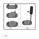
Страница 4: ...4 NL Fig 1 Fig 2 ...

Страница 5: ...s de batterij met de gegraveerde plus blijvend zichtbaar eerst aan de zijde in de houder en daarna wordt de batterij aan de zijde vast geklikt in de houder fig 1 Batterij vervangen Demonteer de batterij met een schroevendraaier fig 2 aan de zijde uit de houder Na het vervangen van de batterij blijven de opgeslagen functies behouden Let op Gooi lege batterijen niet bij het huisvuil maar breng ze na...

Страница 6: ...A fig 4 met de bijgeleverde plakstroken D op een glad vlak oppervlak dit mag geen metaalachtige oppervlakte zijn 2 Plaats de draadloze schakelaar C fig 5 zodanig in het frame B dat hij vastklikt 3 Plaats de draadloze schakelaar met frame ca 5mm boven de borgplaat A en breng deze naar beneden totdat hij in de klauwen van de borgplaat vastklikt fig 6 Let op De zender heeft een IP classificatie van I...

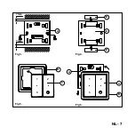
Страница 7: ...NL 7 B C A C B 7 mm 7 mm A D D A Fig 3 Fig 5 Fig 4 Fig 6 1 2 3 1 2 3 ...

Страница 8: ...gsklauwen vast in de borgplaat Trek het frame er nooit af zonder hem vooraf naar boven te schuiven omdat anders de borgplaat wordt beschadigd fig 7 1 Schuif de draadloze schakelaar met frame ca 5mm naar boven 2 Trek nu de schakelaar met frame los ...

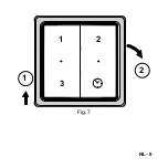
Страница 9: ...NL 9 1 2 1 2 3 Fig 7 ...

Страница 10: ...oge stofdoek of met een stofzuiger Let op De zender niet nat reinigen Bediening Functies voor de gebruiker Knop Actie Functieomschrijving 1 Kort Stand 1 laag 2 Kort Stand 2 middel 3 Kort Stand 3 hoog Kort Stand 3 tijdelijk 10 minuten Lang 2sec Stand 3 tijdelijk 30 minuten ...

Страница 11: ...steem en schakel daarna de spanning weer in Er is nu 10 minuten tijd om te programmeren 2 Houd de drukknop 1 drukknop tenminste 6 sec ingedrukt 3 De beide indicaties lichten rood en daarna groen op Het afstemmen is voltooid de schakelaar krijgt het adres van het ventilatietoestel 4 Test de 3 standen na het programmeren van de schakelaar Voor de tweede of volgende schakelaar herhaal stap 1 t m 4 ...

Страница 12: ...minuten tijd om te programmeren 2 Houd de drukknop 2 drukknop tenminste 6 sec ingedrukt 3 De beide indicaties lichten rood en daarna groen op Het afstemmen is voltooid het ventilatietoestel krijgt het adres van de schakelaar 4 Test de 3 standen na het programmeren van de schakelaar Voor de tweede of volgende ventilatietoestel herhaal stap 1 t m4 ...

Страница 13: ...e spanning weer in Er is nu 10 minuten tijd om te programmeren 2 Houd de drukknop 3 drukknop tenminste 6 sec ingedrukt 3 De beide indicaties lichten rood en daarna groen op Het afstemmen is voltooid het ventilatietoestel R krijgt een willekeurig adres van de schakelaar 4 Test de 3 standen na het programmeren van de schakelaar ...

Страница 14: ...and 3 gezet Beide LED s lichten 1 seconde rood op het ventilatietoestel heeft na een aantal pogingen nog niet gereageerd Beide LED s lichten afwisselend rood op De schakelaar staat in de afstemmingsmode maar de het ventilatietoestel niet Er kan daardoor geen afstemming plaatsvinden Het afwisselend knipperen duurt ca 1 minuut Beide LED s lichten 1 seconde groen op De afstemming is voltooid ...

Страница 15: ...NL 15 ...

Страница 16: ...16 EN Delivery includes RFZ remote control 1 x Battery type CR 2032 1 x Tape 14 x 33 mm 2 x Fixing screws 2 x Fixing plugs 2 x Manual 1 x ...

Страница 17: ...the transmitter s and receiver must be tuned to each other The receiver can easily be retro fitted to a ventilation unit without standard RF control Once the 3 position switch receiver combination has been fitted the highest activated rpm is the benchmark The receiver can simply be affixed or screwed to the wall The remote control is powered by a lithium battery type CR 2032 A new battery has a li...

Страница 18: ...18 EN Fig 1 Fig 2 ...

Страница 19: ...ch Insert the battery on the side of the holder with the engraved plus facing up and then push the battery in place on the side fig 1 Battery replacement Lift the battery out of the holder on the side by means of a screwdriver fig 2 Saved functions are retained during battery replacement Note Do not throw empty batteries out with the household refuse but take them to your nearest collection point ...

Страница 20: ...ffix locking plate A fig 4 onto a smooth level surface no metal surface by means of the self adhesive strips D 2 Place cordless switch C fig 5 into frame B until it clicks into position 3 Place the cordless switch and frame approx 5 mm above locking plate A and lower it until it clicks tight into the fastening lugs of the locking plate fig 6 Note The remote control is IP40 classified and should th...

Страница 21: ...EN 21 B C A C B 7 mm 7 mm A D D A Fig 3 Fig 5 Fig 4 Fig 6 1 2 3 1 2 3 ...

Страница 22: ...e frame securely in the locking plate Never pull the frame off without first lifting it upwards otherwise you could damage the locking plate fig 7 1 Slide the cordless switch and frame upwards by approx 5 mm 2 Now remove the switch and frame ...

Страница 23: ...EN 23 1 2 1 2 3 Fig 7 ...

Страница 24: ... or a vacuum cleaner Note Do not wet clean the remote control Operation Functions for the user Button Action Function description 1 Short Position 1 low 2 Short Position 2 medium 3 Short Position 3 high Short Position 3 temporary 10 minutes Long 2 sec Position 3 temporary 30 minutes ...

Страница 25: ...lation system and then switch the power back on You now have 10 minutes to program the unit 2 Press 1 button for at least 6 sec 3 Both indicators turn red and then green Tuning is complete the switch receives the address of the ventilation unit 4 Test the 3 settings after programing the switch For a second switch or further switches repeat steps 1 to 4 ...

Страница 26: ...n You now have 10 minutes to program the unit 2 Press 2 button for at least 6 sec 3 Both indicators turn red and then green Tuning is complete the ventilation unit receives the address of the switch 4 Test the 3 settings after programing the switch For a second ventilation unit or further units repeat steps 1 to 4 ...

Страница 27: ...tem and then switch the power back on You now have 10 minutes to program the unit 2 Press 3 button for at least 6 sec 3 Both indicators turn red and then green Tuning is complete the ventilation unit R receives an arbitrary address of the switch 4 Test the 3 settings after programing the switch ...

Страница 28: ... 2 or temporarily in position 3 Both LEDs light up red for 1 second after a number of attempts the ventilation unit has still not reacted Both LEDs light up alternately red The switch is in the fine tune mode but the ventilation unit is not Fine tuning is therefore not possible This alternate flashing continues for approx 1 minute Both LEDs light up green for 1 second Tuning is complete ...

Страница 29: ...EN 29 ...

Страница 30: ...30 DE Lieferumfang RFZ Fernbedienung 1 Stück Batterie Typ CR 2032 1 Stück Klebeband 14 x 33 mm 2 Stück Befestigungsschrauben 2 Stück Befestigungsdübel 2 Stück Betriebsanleitung 1 Stück ...

Страница 31: ... müssen der die Sender erst auf den Empfänger abgestimmt werden Der Empfänger lässt sich problemlos nachträglich an einem Lüftungsgerät ohne Standard Funkfernbedienung RF installieren Sobald die Kombination 3 Stufenschalter Empfänger installiert ist richtet sich das Gerät jeweils nach der höchsten eingeschalteten Drehzahl Der Sender lässt sich einfach an die Wand kleben oder schrauben Die Fernbedi...

Страница 32: ...32 DE des Schalters verkürzt sich die Lebensdauer Abb 1 Abb 2 ...

Страница 33: ...die Batterie mit dem eingravierten Pluszeichen sichtbar nach oben erst an der Seite in den Halter und drücken Sie sie anschließend an der Seite fest in den Halter Abb 1 Batterie ersetzen Lösen Sie die Batterie mit Hilfe eines Schraubendrehers Abb 2 an der Seite aus dem Halter Beim Batteriewechsel bleiben die gespeicherten Funktionen erhalten Achtung Werfen Sie leere Batterien nicht in den Hausmüll...

Страница 34: ... Abb 4 auch mit Hilfe der mitgelieferten Klebestreifen D auf einer glatten flachen Oberfläche befestigen keine metallartige Oberfläche 2 Platzieren Sie den drahtlosen Schalter C Abb 5 so im Rahmen B dass er einrastet 3 Platzieren Sie den drahtlosen Schalter mit Rahmen ca 5 mm über der Sicherungsplatte A und bewegen Sie ihn nach unten bis er in den Klemmen der Sicherungsplatte einrastet Abb 6 Vorsi...

Страница 35: ...DE 35 B C A C B 7 mm 7 mm A D D A Fig 3 Fig 5 Fig 4 Fig 6 1 2 3 1 2 3 ...

Страница 36: ... Sicherungsplatte befestigt Ziehen Sie den Rahmen niemals einfach ab sondern schieben Sie ihn erst nach oben da Sie sonst die Sicherungsplatte beschädigen Abb 7 1 Schieben Sie den drahtlosen Schalter mit Rahmen ca 5 mm nach oben 2 Ziehen Sie nun den Schalter mit Rahmen los ...

Страница 37: ...DE 37 1 2 1 2 3 Abb 7 ...

Страница 38: ...Staub von der RFZ entfernen Vorsicht Die RFZ nicht nass reinigen Bedienung Funktionen für den Benutzer Taste Aktion Funktionsbeschreibung 1 Kurz Stufe 1 niedrig 2 Kurz Stufe 2 mittel 3 Kurz Stufe 3 hoch Kurz Stufe 3 vorübergehend 10 Minuten Lang 2 Sek Stufe 3 vorübergehend 30 Minuten ...

Страница 39: ...eder ein Sie haben nun 10 Minuten Zeit das Gerät zu programmieren 2 Halten Sie die Taste 1 mindestens 6 Sekunden lang gedrückt 3 Die beiden LED Anzeigen leuchten rot und danach grün auf Die Abstimmung ist abgeschlossen Der Schalter erhält die Adresse vom Lüftungsgerät 4 Testen Sie die 3 Stellungen nach dem Programmieren des Schalters Für den zweiten oder jeden weiteren Schalter Wiederholen Sie die...

Страница 40: ...rogrammieren 2 Halten Sie die Taste 2 Taste mindestens 6 Sekunden lang gedrückt 3 Die beiden LED Anzeigen leuchten rot und danach grün auf Die Abstimmung ist abgeschlossen Das Lüftungsgerät erhält die Adresse von Schalter 4 Testen Sie die 3 Stellungen nach dem Programmieren des Schalters Für das zweite oder jedes weitere Lüftungsgerät Wiederholen Sie die Schritte 1 bis 4 ...

Страница 41: ...n Sie haben nun 10 Minuten Zeit das Gerät zu programmieren 2 Halten Sie die Taste 3 mindestens 6 Sekunden lang gedrückt 3 Die beiden LED Anzeigen leuchten rot und danach grün auf Die Abstimmung ist abgeschlossen Das Lüftungsgerät R erhält eine beliebige Adresse vom Schalter 4 Testen Sie die 3 Stellungen nach dem Programmieren des Schalters ...

Страница 42: ...ufe 3 gestellt Beide LEDs leuchten 1 Sekunde lang rot auf Das Lüftungsgerät hat nach einigen Versuchen noch nicht reagiert Beide LEDs leuchten abwechselnd rot auf Der Schalter steht im Abstimmungsmodus aber das Lüftungsgerät nicht Dadurch ist eine Abstimmung nicht möglich Die LEDs blinken abwechselnd ca 1 Minute lang Beide LEDs leuchten 1 Sekunde lang grün auf Die Abstimmung ist abgeschlossen ...

Страница 43: ...DE 43 ...

Страница 44: ...44 FR Contenu de livraison Télécommande RFZ 1 pièce Pile type CR 2032 1 pièce Bande adhésive 14 x 33 mm 2 pièces Vis de fixation 2 pièces Chevilles de fixation 2 pièces Manuel 1 pièce ...

Страница 45: ...distance il faut d abord régler l les émetteur s sur le récepteur Le récepteur s installe ensuite aisément sur l appareil de ventilation sans une standard contrôle sans fil RF Si la combinaison Interrupteur à 3 positions récepteur est installée le ventilateur tourne au régime le plus élevé L émetteur peut facilement être collé ou vissé au mur La télécommande fonctionne avec une pile au lithium typ...

Страница 46: ...46 FR Fig 1 Fig 2 ...

Страница 47: ... pile dans le compartiment avec l indication du plus restant visible d abord du côté puis appuyez sur l autre côté afin que la pile s enclenche fig 1 Remplacement de la pile À l aide d un tournevis fig 2 délogez la pile du côté du compartiment Après le remplacement de la pile les fonctions mémorisées sont sauvegardées Attention Ne jetez pas les piles usagées aux ordures ménagères mais déposez les ...

Страница 48: ...urface lisse plane la surface ne peut pas être métallique à l aide des bandes adhésives livrées D 2 Positionnez l interrupteur sans fil C fig 5 de sorte qu il s encliquette dans le cadre B 3 Positionnez l interrupteur sans fil avec le cadre 5 mm environ au dessus de la plaque de retenue A et abaissez le jusqu à ce qu il s encliquette dans les griffes de la plaque de retenue fig 6 Attention Le télé...

Страница 49: ...FR 49 B C A C B 7 mm 7 mm A D D A Fig 3 Fig 5 Fig 4 Fig 6 1 2 3 1 2 3 ...

Страница 50: ...griffes de fixation Ne retirez jamais le cadre sans le faire coulisser au préalable vers le haut sinon la plaque de retenue sera endommagée fig 7 1 Faites glisser l interrupteur sans fil avec le cadre 5 mm environ vers le haut 2 Détachez alors l interrupteur avec le cadre ...

Страница 51: ...FR 51 1 2 1 2 3 Fig 7 ...

Страница 52: ...irateur Attention Pas de nettoyage humide pour le télécom mande Utilisation Fonctions pour l utilisateur Bouton Action Description de la fonction 1 Bref Position 1 basse 2 Bref Position 2 moyenne 3 Bref Position 3 haute Bref Position 3 temporaire 10 minutes Prolongée 2 sec Position 3 temporaire 30 minutes ...

Страница 53: ...on Vous disposez maintenant de 10 minutes pour programmer 2 Maintenez le bouton poussoir 1 bouton poussoir appuyé pendant au moins 6 secondes 3 Les deux voyants lumineux s allument en rouge puis en vert La mise au point est achevée l interrupteur obtient l adresse de l appareil de ventilation 4 Testez les 3 positions après la programmation de l interrupteur Pour le deuxième interrupteur ou l inter...

Страница 54: ...z le bouton poussoir 2 bouton poussoir appuyé pendant au moins 6 secondes 3 Les deux voyants lumineux s allument en rouge puis en vert La mise au point est achevée l appareil de ventilation obtient l adresse de l interrupteur 4 Testez les 3 positions après la programmation de l interrupteur Pour le deuxième appareil de ventilation ou l appareil de ventilation suivant répétez les étapes 1 à 4 inclu...

Страница 55: ...ez maintenant de 10 minutes pour programmer 2 Maintenez le bouton poussoir 3 bouton poussoir appuyé pendant au moins 6 secondes 3 Les deux voyants lumineux s allument en rouge puis en vert La mise au point est achevée l appareil de ventilation R obtient une adresse aléatoire de l interrupteur 4 Testez les 3 positions après la programmation de l interrupteur ...

Страница 56: ...en position 3 Les deux voyants lumineux s allument en rouge pendant 1 seconde l appareil de ventilation n a toujours pas réagi au bout de plusieurs tentatives Les deux voyants lumineux s allument en rouge en alternance l interrupteur est en mode de réglage mais pas l appareil de ventilation Une mise au point ne peut donc pas avoir lieu Le clignotement dure 1 minute environ Les deux voyants lumineu...

Страница 57: ...FR 57 ...

Страница 58: ...58 IT Contenuto fornitura Telecomando RFZ 1 pezzo Batteria tipo CR 2032 1 pezzo Nastro 14 x 33 mm 2 pezzo Viti di fissaggio 2 pezzo Tasselli di fissaggio 2 pezzo Manuale 1 pezzo ...

Страница 59: ...e occorre prima sintonizzare il i trasmettitore i sul ricevitore Il ricevitore può essere facilmente installato sull unità di ventilazione in un secondo momento senza standard comando a radiofrequenze RF Una volta installato il gruppo Interrruttore a 3 posizioni ricevitore l apparecchio funzionerà alla velocità più alta Il trasmettitore può essere facilmente attaccato o avvitato al muro Il telecom...

Страница 60: ...60 IT Fig 1 Fig 2 ...

Страница 61: ...ire la batteria prima dalla parte con il nello scomparto facendo in modo che il simbolo più resti visibile quindi incastrare la batteria dalla parte con il fig 1 Sostituzione batteria Smontare la batteria con un cacciavite fig 2 dalla parte con il dello scomparto Le funzioni memorizzate restano attive anche dopo la sostituzione della batteria Attenzione le batterie esauste non vanno gettate nei ri...

Страница 62: ... sicurezza A fig 4 con le strisce adesive D fornite in dotazione su una superficie liscia piana non metallica 2 Inserire l interruttore wireless C fig 5 nella cornice B in modo che si incastri 3 Posizionare l interruttore wireless con la cornice a circa 5 mm sopra la piastra di sicurezza A e portarlo verso il basso fino a quando non si bloccherà nelle scanalature della piastra fig 6 Attenzione l t...

Страница 63: ...IT 63 B C A C B 7 mm 7 mm A D D A Fig 3 Fig 5 Fig 4 Fig 6 1 2 3 1 2 3 ...

Страница 64: ...ezza Non estrarre mai la cornice senza prima averla spostata verso l alto in caso contrario si potrebbe danneggiare la piastra di sicurezza fig 7 1 Spostare l interruttore wireless con la cornice di circa 5 mm verso l alto 2 A questo punto estrarre l interruttore senza fili con la cornice ...

Страница 65: ...IT 65 1 2 1 2 3 Fig 7 ...

Страница 66: ...on un aspirapol vere Attenzione non bagnare l telecomando per pulirlo Funzionamento Funzioni per l utente Tasto Azione Descrizione della funzione 1 Breve Posizione 1 bassa 2 Breve Posizione 2 media 3 Breve Posizione 3 alta Breve Posizione 3 temporanea 10 minuti Lunga 2 sec Posizione 3 temporanea 30 minuti ...

Страница 67: ...te A questo punto avrete 10 minuti di tempo per la programmazione 2 Tenere premuti per almeno 6 sec il tasto 1 il tasto 3 Entrambi gli indicatori si illumineranno di rosso e poi di verde La sintonizzazione è conclusa all interruttore viene assegnato l indirizzo dall unità di ventilazione 4 Dopo aver programmato l interruttore verificare che le 3 posizioni funzionino Per i successivi interruttori r...

Страница 68: ...ogrammazione 2 Tenere premuto il tasto 2 il tasto per almeno 6 sec 3 Entrambi gli indicatori si illumineranno di rosso e poi di verde La sintonizzazione è conclusa all unità di ventilazione viene assegnato l indirizzo dall interruttore 4 Dopo aver programmato l interruttore verificare che le 3 posizioni funzionino Per i successivi interruttori ripetere i passaggi dall 1 al 4 ...

Страница 69: ...unto avrete 10 minuti di tempo per la programmazione 2 Tenere premuti per almeno 6 sec il tasto 3 il tasto 3 Entrambi gli indicatori si illumineranno di rosso e poi di verde La sintonizzazione è conclusa L interruttore assegna un indirizzo arbitrario all unità di ventilazione R 4 Dopo aver programmato l interruttore verificare che le 3 posizioni funzionino ...

Страница 70: ...ne 2 o temporaneamente in posizione 3 Entrambi i LED diventano rossi per 1 secondo l unità di ventilazione non ha ancora risposto dopo alcuni tentativi Entrambi i LED lampeggiano di rosso l interruttore è in modalità sintonizzazione ma l unità di ventilazione no Non è quindi possibile effettuare la sintonizzazione I LED lampeggiano per circa 1 minuto Entrambi i LED diventano verdi per 1 secondo la...

Страница 71: ...IT 71 ...

Страница 72: ...72 PL Dostawa obejmuje następujące elementy Pilot zdalnego sterowania RFZ 1 x Bateria typu CR 2032 1 x Taśma 14 x 33 mm 2 x Wkręty mocujące 2 x Kołki mocujące 2 x Instrukcja obsługi 1 x ...

Страница 73: ...trzeba najpierw zestroić nadajnik i z odbiornikiem Odbiornik można łatwo wstecznie dopasować do urządzenia wentylacyjnego bez standardowego sterowanie bezprzewodowe RF Po spasowaniu kombinacji gniazda Przełącznik 3 pozycyjny i odbiornika najwyższa aktywowana wartość obr min jest wzorcowa Odbiornik można zwyczajnie przykleić czy przykręcić do ściany Pilot zdalnego sterowania jest zasilany przez bat...

Страница 74: ...74 PL ona używana tym krótszy jest okres eksploatacji Rys 1 Rys 2 ...

Страница 75: ...eść z tyłu przełącznika Umieść baterię po stronie uchwytu z wyrytym znakiem plus skierowanym ku górze a następnie wepchnij baterię na miejsce po stronie rys 1 Wymiana baterii Wyjmij baterię z uchwytu po stronie za pomocą śrubokręta rys 2 Zapisane funkcje zostaną zachowane podczas wymiany baterii Uwaga Nie wyrzucaj zużytych baterii razem z odpadami domowymi ale oddaj je w najbliższym punkcie zbiórk...

Страница 76: ... rys 4 można też przykleić do gładkiej płaskiej powierzchni nie metalowej za pomocą pasków samoprzylepnych D 2 Umieść przełącznik bezprzewodowy C rys 5 w ramce B aż zatrzaśnie się we właściwym położeniu 3 Umieść przełącznik bezprzewodowy z ramką ok 5 mm nad płytką ustalającą A i opuść go aż dokładnie się zatrzaśnie w uchach mocujących płytki ustalającej Rys 6 Uwaga Przełącznik sterowania posiada s...

Страница 77: ...PL 77 B C A C B 7 mm 7 mm A D D A Fig 3 Fig 5 Fig 4 Fig 6 1 2 3 1 2 3 ...

Страница 78: ...e w płytce ustalającej Nie wolno wyciągać ramki bez jej uprzedniego podniesienia ponieważ w takim wypadku mogłoby dojść do uszkodzenia płytki ustalającej Rys 7 1 Przesuń przełącznik bezprzewodowy z ramką o ok 5 mm w górę 2 Następnie usuń przełącznik z ramką ...

Страница 79: ...PL 79 1 2 1 2 3 Rys 7 ...

Страница 80: ...ściereczki lub odkurzacza Uwaga Przełącznika sterowania nie wolno czyścić na mokro Obsługa Funkcje dla użytkownika Przycisk Czynność Opis funkcji 1 Krótka Pozycja 1 niska 2 Krótka Pozycja 2 średnia 3 Krótka Pozycja 3 wysoka Krótka Pozycja 3 tymczasowa 10 minut Długa 2 sek Pozycja 3 tymczasowa 30 minut ...

Страница 81: ... włącz zasilanie z powrotem W ciągu 10 minut zaprogramuj urządzenie 2 Naciśnij przycisk 1 przycisk i przytrzymaj przez co najmniej 6 sek 3 Oba wskaźniki zaświecą na czerwono a następnie na zielono Strojenie zostało ukończone przełącznik otrzymuje adres urządzenia wentylacyjnego 4 Po zaprogramowaniu przełącznika sprawdź 3 ustawienia W przypadku drugiego lub kolejnych przełączników powtórz czynności...

Страница 82: ...dzenie 2 Naciśnij przycisk 2 przycisk i przytrzymaj przez co najmniej 6 sek 3 Oba wskaźniki zaświecą na czerwono a następnie na zielono Strojenie zostało ukończone urządzenie wentylacyjne otrzymuje adres przełącznika 4 Po zaprogramowaniu przełącznika sprawdź 3 ustawienia W przypadku drugiego lub kolejnych urządzeń wentylacyjnych powtórz czynności od 1 do 4 ...

Страница 83: ...z powrotem W ciągu 10 minut zaprogramuj urządzenie 2 Naciśnij przycisk 3 przycisk i przytrzymaj przez co najmniej 6 sek 3 Oba wskaźniki zaświecą na czerwono a następnie na zielono Strojenie zostało ukończone urządzenie wentylacyjne R otrzymuje dowolny adres przełącznika 4 Po zaprogramowaniu przełącznika sprawdź 3 ustawienia ...

Страница 84: ...sowo w pozycji 3 Obie diody LED świecą na czerwono przez 1 sekundę po szeregu prób urządzenie wentylacyjne nadal nie reaguje Obie diody LED świecą na czerwono naprzemiennie Przełącznik pracuje w trybie dostrajania ale urządzenie wentylacyjne nie W związku z tym dostrojenie jest niemożliwe To naprzemienne błyskanie trwa przez ok 1 minutę Obie diody LED świecą na zielono przez 1 sekundę Strojenie zo...

Страница 85: ...PL 85 ...

Страница 86: ...86 PL ...

Страница 87: ...PL 87 ...

Страница 88: ...Nederland B V Lingenstraat 2 8028 PM Postbus 621 8000 AP Zwolle T 31 38 429 69 11 F 31 38 422 56 94 info zehnder jestorkair nl www zehnder jestorkair nl ZGNL Manual_D20050404 V0413 NL_EN_DE_FR_IT_PL Subject to change ...

Отзывы: