


zebris Medical GmbH
FDM-T Technical Data and Operating Instructions
Page 39/65
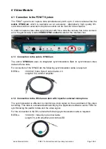
Modes
Characteristics
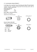
Pin Assignment
PULSE
SYNC
ESD - protected, voltage reversal proof input
Input resistance: 2K
(Pull-Up)
VIH (High-Level Input Voltage): 2.0V
VIL (Low-Level Input Voltage): 0.8V
Polarity: Lo Active
When mode PULSE SYNC is used LED bright-
ness is set to 150%.
The shutter output of industrial high speed cam-
eras can be used as trigger signal for the
PULSE SYNC.
By utilizing pulsed light optimal lighting condi-
tions for industrial cameras can be accom-
plished without being too bright or disturbing for
the human eyesight.
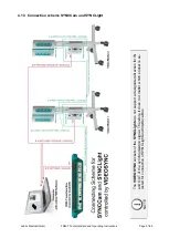
In order to use PULSE SYNC the
SYNC mode
switch
has to be set to position
SYNC
.
6-Pin Socket
Pin4: Input
Pin5: GND
Socket Type
HIROSE
HR10A-7P-6S
Camera Trigger
Input
Begin of
Illumination
Timing Properties when
switching the Light
ON:
Delay of 50µS
The cameras Trigger-Output
should be preset to this Value.
Delay: 50µS
Camera Trigger
Input
End of
Illumination
No Delay!
Timing Properties when
switching the Light
OFF:
No Delay (0µS)
No adjustment of
Trigger-Output necessary!