background image


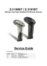
 Z-3190BT/Z-3191BT Service Guide  

3 / 11

S

ERVICE  

G

UIDE

Laser Light Viewing

: The scan window is the only aperture through which laser light may be observed from this 

product. A failure of the scanner engine, while the laser diode continues to emit a laser beam, may cause emission 
levels to exceed those for safe operation. The scanner has safeguards to prevent this occurrence. If, however, a 
stationary laser beam is emitted, the failing scanner should be disconnected from its power source immediately. 


Adjustments

: Do not attempt any adjustments or alteration of this product. Do not remove the protective housing 

of the scanner. There are no user-serviceable parts inside. 


Optical

: The use of optical instruments with this product will increase the eye hazard.  Optical instruments include 

binoculars, magnifying glasses, and microscopes but do not include normal eye glasses worn by the user. 


CAUTION

: Use of controls or adjustments or performance of procedures other than those specified herein may 

result in hazardous radiation exposure. 


For CE-Countries 

 
This scanner is in conformity with CE standards. Please note that an approved, CE-marked power supply unit 
should be used in order to maintain CE conformance. 
 

This manual is in A4 format. Please check your printer setting before printing it out.


Power Supply 


Use only the type of battery and the charging equipments that came with your scanner. 


Using any other type of battery and charging equipment may damage the scanner and invalidate the warranty. 


Do not short the battery terminals. The battery could overheat. 


Do not attempt to split or peel the outer casing. 


Remove the battery if the scanner is not going to be used for a long time. If the battery is left unused for more 

than 3 months, you need to charge the battery before use. 


WARNING 


Improper assembly/disassembly may result in performance degradation to the wireless 
and other functions of the scanner. Use this service guide at your own risk. We do not 
guarantee or warranty the timeliness, completeness, or performance of the information 
provided in this service guide.

Содержание z3190BT

Страница 1: ...r Service Guide Revision History Changes to the original manual are listed below Version Date Description of Version 1 0 Jan 31 2013 Initial release 1 1 May 22 2014 New handle base 1 2 Sept 20 2015 Up...

Страница 2: ...e when operated in a commercial environment Radio and Television Interference Operation of this equipment in a residential area can cause interference to radio or television reception This can be dete...

Страница 3: ...e of procedures other than those specified herein may result in hazardous radiation exposure For CE Countries This scanner is in conformity with CE standards Please note that an approved CE marked pow...

Страница 4: ...s Preface 2 Important Notice 2 Radio Notice 2 Radio and Television Interference 2 Laser Safety 2 For CE Countries 3 Power Supply 3 WARNING 3 Introduction 5 Product Overview 5 Scanner Parts 6 Take Apar...

Страница 5: ...with a state of the art scan engine Featuring a superb scanning speed and able to withstand 1 5 meter drop it is ideal for manufacturing and logistic sectors Superb scanning ability Proprietary hardwa...

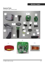
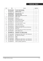
Страница 6: ...Z 3190BT Z 3191BT Service Guide 6 11 SERVICE GUIDE Scanner Parts The scanner includes the following parts 1 2 3 4 1 5 6 1 7 8 9 10 11 12 13 14 15 1 16 17 18 6 2 15 2 4 2...

Страница 7: ...engine assenbly rubber 1 6 2 863 191BT0 501 Laser engine assembly 1 7 564 031900 412 Buyzzer sound guide panel 1 8 521 614000 015 Self tapping screw M3 15 0mm round Torx head 2 9 644 7319X0 000 Mylar...

Страница 8: ...Instructions Read these instructions completely before you begin Follow all instructions Heed all warnings Tools to Prepare Philips screwdriver Please follow these steps to take apart the scanner 1 R...

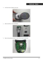
Страница 9: ...3190BT Z 3191BT Service Guide 9 11 SERVICE GUIDE 3 Unscrew the screws pointed by red arrow 4 Remove the battery cover and the battery 5 Remove the mylar tape and the FCC cable Then remove the main boa...

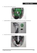
Страница 10: ...1BT Service Guide 10 11 SERVICE GUIDE 6 Remove the screws pointed by red arrows 7 Separate handle base battery power charge board assembly from the buzzer sound guide panel 8 Remove the screws pointed...

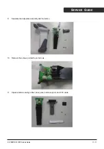
Страница 11: ...Z 3191BT Service Guide 11 11 SERVICE GUIDE 9 Separate the baseplate assembly and the button 10 Remove the screws pointed by red arrows 11 Sparate button sealing rubber base plate button support and F...

Отзывы: