


YZ Systems Milton Roy • 201 Ivyland Road • Ivyland, Pennsylvania • USA • 18974 • P: 281.362.6500 • www.yzsystems.com
Page 27
NJEX EUR ver. 08-2021
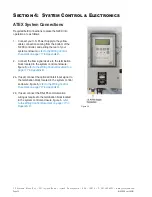
Section 5: Programming for Proportional-to-Flow Operation
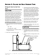
Or
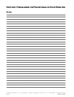
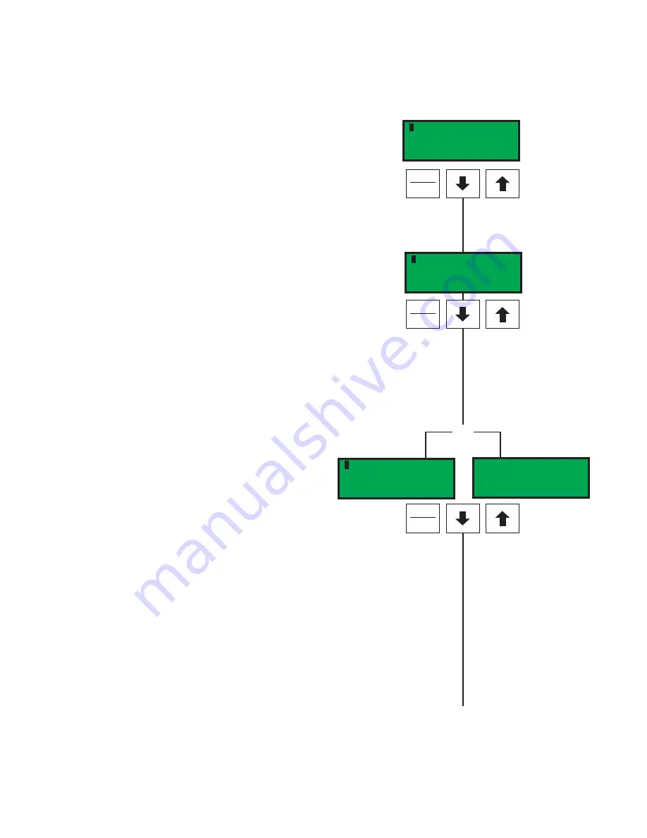
pmp bat vmtr sig tnk
Odorant Output
0.010 lbs/pulse
pmp bat vmtr sig tnk
Odorant Output
0.010 kg/pulse
Figure 38
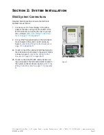
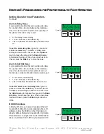
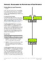
pmp bat vmtr sig tnk
Maximum Time/Stroke
0 = Disabled
Figure 37
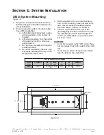
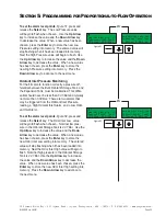
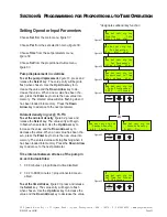
To set the flow
(no signal)
input
,
figure 36a,
press
and release the
Select
key. The value entry will begin
to flash when selected. Use the
Up Arrow
key to
increase the value and the
Down Arrow
key to de-
crease the value. When a new value has been cho-
sen, press the
Enter
key to store the new value into
memory. The entered value will stop flashing when it
has been loaded into the memory. Press the
Down
Arrow
key to advance to the next parameter.
Maximum Time/Stroke
The maximum time/stroke setting
, is the maximum
time between strokes, when a stroke time is actually
calculated, desired regardless of the time calculated
by the controller.
This feature is not active under low-
flow or no-flow conditions.
To set the maximum time/stroke
,
figure 37,
press
and release the
Select
key. The value entry will begin
to flash when selected. Use the
Up Arrow
key to
increase the value and the
Down Arrow
key to de-
crease the value. When a new value has been cho-
sen, press the
Enter
key to store the new value into
memory. The entered value will stop flashing when it
has been loaded into memory. Press the
Down Ar-
row
key to advance to the next parameter.
The Odorant Output Setting
The odorant output setting
, controls the scaling of
the odorant output relay in lbs/pulse
(kg/pulse)
. This
indicates how much odorant has been injected with
each pulse of the output relay located
TB1
, terminals
#19
and
#20
,
refer to the Wiring Control Document on
page 117 in Appendix D: Documents
To set the odorant output
,
figure 38,
press and
release the
Select
key. The value entry will begin
to flash when selected. Use the
Up Arrow
key to
increase the value and the
Down Arrow
key to de-
crease the value. When a new value has been cho-
sen, press the
Enter
key to store the new value into
memory. The entered value will stop flashing when it
has been loaded into memory. Press the
Down Ar-
row
key to advance to the next parameter.
pmp bat vmtr sig tnk
Flow (No Signal)
20.0% Max Gas Flow
Figure 36a
Содержание NJEX 6300G
Страница 1: ...NJEX 6300G 7300G N A T U R A L G A S O D O R I Z A T I O N S Y S T E M...
Страница 2: ......
Страница 3: ...NJEX 6300G 7300G Instruction Operating Manual Version 08 2021...
Страница 4: ......
Страница 10: ......