background image

YZ Systems, Inc. • 3101 Pollok Drive • Conroe, Texas • USA • 77303 • P: 936.788.5593 • F: 936.788.5720
Page 4

DP-2010JF  ver.05202005

SSSSS

ECTION

ECTION

ECTION

ECTION

ECTION

 1:  F

 1:  F

 1:  F

 1:  F

 1:  F

IRST

IRST

IRST

IRST

IRST

 T

 T

 T

 T

 T

HINGS

HINGS

HINGS

HINGS

HINGS

 T

 T

 T

 T

 T

O

O

O

O

O

 K

 K

 K

 K

 K

NOW

NOW

NOW

NOW

NOW

 A

 A

 A

 A

 A

BOUT

BOUT

BOUT

BOUT

BOUT

 T

 T

 T

 T

 T

HE

HE

HE

HE

HE

 D

 D

 D

 D

 D

YNA

YNA

YNA

YNA

YNA

PPPPP

AK

AK

AK

AK

AK

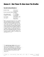
System Accessories

• The External Power Option can be used in lieu of

the internal battery pack.  The External Power
Option (model # EPO-120) consists of an AC to
DC convertor and intrinsically safe barrier to
convert 120 VAC power to 28 VDC to operate the
controller without the use of the internal battery
pack.

• The Solar Power Option would be used in lieu of

the internal battery pack.  The Solar Power Option
(model #SPO-12) consists of a 5 watt solar panel
with RM-12 charger regulator module and internal
12V, 5 Amp hour battery pack.

• 

DuraSite,

 portable DOT approved constant pres-

sure sample vessels. Available in 150, 300, 500,
800, and 1000 cc sizes.

• SC-Spun Vessel, portable DOT approved (1800 psi

maximum working pressure), sample vessels.
Available in 300, 500,  and 1000 cc sizes.

• KK-1, KK-2, &  KK-3: carrying cases for DuraSites

that meet DOT requirements for transporting
portable sample vessels.

• 1/4" stainless steel tubing Dielectric Isolator Union.

These should be installed in every tubing line that
attaches the sampler  to the pipeline in any
manner. For example the supply gas, product
connection to the system, and differential pres-
sure switch connections, (P/N A1-0182).

• DPS-2 differential pressure switch for applications

with flow.no-flow conditiona and no flow signal
available.

• LinkPlus  provides a direct link between the

DynaPak, and your sample vessel, providing a
guage, vessel isolation valve, and excess pres-
sure protection.

• YZ BackRack vessel trays are available for direct

support mounting of a sample vessel tray to the
back of the DynaPack. Limited to SC-300 & Sc-
500 Vessels.

A complete line of sampling accessories ranging
from sample probes to sample vessels is available
through YZ.  Please contact your local representa-
tive or  YZ toll free at 800.344.5399. For technical
support call 800.653.9435.

Содержание DynaPak DP-2010JF

Страница 1: ...DynaPak GasSampler S Y S T E M S U P P O R T M A N U A L DP 2010JF...

Страница 2: ......

Страница 3: ...DP 2010JF INSTRUCTION OPERATING MANUAL Version 05202005...

Страница 4: ......

Страница 5: ...ematic 6 Standard System Mounting 7 Standard System Connections 8 Optional DPS 2 Installation 9 Section 3 Sample Vessel Installation 11 Variable Pressure Constant Volume Cylinders 11 Variable Volume C...

Страница 6: ...Section 39 ForAdditional Help 39 Step by Step Resolution 39 Battery Power 40 Battery Power Troubleshooting Steps 40 Z 65 Counter Mode 41 Z 65 Counter Mode Troubleshooting Steps 41 Z 65 Timer Mode 42...

Страница 7: ...bat PDF format will be highlighted further in blue italic text indicating the copy retains a hyperlink to the referenced item Measurement units are listed in italic parenthesis text following their US...

Страница 8: ...tures below 32 F 0 C condition ing of the actuation gas supply may be required Where the actuation gas supply has a high water content and or a low hydrocarbon dew point addi tional actuation gas filt...

Страница 9: ...sed sampling with the YZ differential pressure switch DPS 2 this mode of operation is similar to the time based sampling mode except that the DPS 2 converts a differential pressure signal to an electr...

Страница 10: ...Available in 150 300 500 800 and 1000 cc sizes SC Spun Vessel portable DOT approved 1800 psi maximum working pressure sample vessels Available in 300 500 and 1000 cc sizes KK 1 KK 2 KK 3 carrying case...

Страница 11: ...educing pressure from line pressure of up to 1500 psi down to system supply pressures in one step Low Power Solenoid figure 1 provides interface between the Z 65 Electronic Controller and the Pump Pne...

Страница 12: ...6 788 5593 F 936 788 5720 Page 6 DP 2010JF ver 05202005 S S S S SECTION ECTION ECTION ECTION ECTION 2 2 2 2 2 S S S S SY Y Y Y YSTEM STEM STEM STEM STEM I I I I INST NST NST NST NSTALLA ALLA ALLA ALLA...

Страница 13: ...from any device which could cause aerosols or significant pressure drops 2 The sampler should not be located within the defined meter tube region AGA 3 manual A The number of unobstructed straight pi...

Страница 14: ...lve and purge valve are closed f After pipeline pressure has been applied to the sampler check the probe body pipeline connec tion using a liquid leak detector CA CA CA CA CAUTION UTION UTION UTION UT...

Страница 15: ...h pressure supply valve without ensuring that the equalization valve is open Failure to do so may damage the DPS 2 s internal components d Open the other supply valve e Close the equalization valve f...

Страница 16: ...A 77303 P 936 788 5593 F 936 788 5720 Page 10 DP 2010JF ver 05202005 S S S S SECTION ECTION ECTION ECTION ECTION 2 2 2 2 2 S S S S SY Y Y Y YSTEM STEM STEM STEM STEM I I I I INST NST NST NST NSTALLA A...

Страница 17: ...sample cylinder 300cc and 500cc spun cylinders may also be installed in a vertical position Piping from the sampler dischage port to the sample vessel should be arranged so that liquid traps are not...

Страница 18: ...5593 F 936 788 5720 Page 12 DP 2010JF ver 05202005 S S S S SECTION ECTION ECTION ECTION ECTION 3 3 3 3 3 S S S S SAMPLE AMPLE AMPLE AMPLE AMPLE V V V V VESSEL ESSEL ESSEL ESSEL ESSEL I I I I INST NST...

Страница 19: ...ery time a sample is required either Proportional To Flow or Time SAFETY NO SAFETY NO SAFETY NO SAFETY NO SAFETY NOTES TES TES TES TES Always use extreme care when performing mainte nance on Sampling...

Страница 20: ...93 F 936 788 5720 Page 14 DP 2010JF ver 05202005 S S S S SECTION ECTION ECTION ECTION ECTION 4 4 4 4 4 S S S S SY Y Y Y YSTEM STEM STEM STEM STEM C C C C CONTR ONTR ONTR ONTR ONTROL OL OL OL OL E E E...

Страница 21: ...led by the host computer or output device that will give an input pulse to the Z 65 controller 1 Determine if the incoming input is either a dry contact or voltage pulse 2 If the input is a dry contac...

Страница 22: ...p displacement per stroke 1cc 2cc 4cc Number of turns open on the pump volume knob 3 6 12 6 Turn the counter dials to the appropriate num ber of pulses you want to count before the sample pump strokes...

Страница 23: ...ON ECTION ECTION ECTION ECTION 5 5 5 5 5 P P P P PR R R R ROGRAMMING OGRAMMING OGRAMMING OGRAMMING OGRAMMING FOR FOR FOR FOR FOR P P P P PR R R R ROPOR OPOR OPOR OPOR OPORTION TION TION TION TIONAL AL...

Страница 24: ...ON ECTION ECTION ECTION ECTION 5 5 5 5 5 P P P P PR R R R ROGRAMMING OGRAMMING OGRAMMING OGRAMMING OGRAMMING FOR FOR FOR FOR FOR P P P P PR R R R ROPOR OPOR OPOR OPOR OPORTION TION TION TION TIONAL AL...

Страница 25: ...e rate from step 1 3 2 0 9 6 8 7 1 3 2 5 4 0 9 1 6 7 8 5 4 12 400 18 36 60 9 13 27 45 3 6 4 9 18 9 15 30 300 200 100 Number of turns open on pump stroke knob sample pump displacement per stroke 1000 c...

Страница 26: ...AL AL AL AL T T T T TO O O O O T T T T TIME IME IME IME IME O O O O OPERA PERA PERA PERA PERATION TION TION TION TION 4 Turn mode switch 1 to on 5 Turn mode switch 2 to on 6 Turn mode switch 3 to on...

Страница 27: ...ECTION ECTION ECTION ECTION ECTION 6 6 6 6 6 P P P P PR R R R ROGRAMMING OGRAMMING OGRAMMING OGRAMMING OGRAMMING FOR FOR FOR FOR FOR P P P P PR R R R ROPOR OPOR OPOR OPOR OPORTION TION TION TION TIONA...

Страница 28: ...ECTION ECTION ECTION ECTION ECTION 6 6 6 6 6 P P P P PR R R R ROGRAMMING OGRAMMING OGRAMMING OGRAMMING OGRAMMING FOR FOR FOR FOR FOR P P P P PR R R R ROPOR OPOR OPOR OPOR OPORTION TION TION TION TIONA...

Страница 29: ...ample 12 400 18 36 60 9 13 27 45 3 6 4 9 18 9 15 30 300 200 100 Number of turns open on pump stroke knob sample pump displacement per stroke 1000 cc 500 cc 300 cc Sample cylinder volumes Sample rate m...

Страница 30: ...mp volume adjustment knob to the value used in the calculations in step 1 4 Turn mode switch 1 to on 5 Turn mode switch 2 to on 6 Turn mode switch 3 to off 7 Turn mode switch 4 to off 8 Press the test...

Страница 31: ...S S S S SECTION ECTION ECTION ECTION ECTION 7 7 7 7 7 P P P P PR R R R ROGRAMMING OGRAMMING OGRAMMING OGRAMMING OGRAMMING FOR FOR FOR FOR FOR P P P P PR R R R ROPOR OPOR OPOR OPOR OPORTION TION TION T...

Страница 32: ...S S S S SECTION ECTION ECTION ECTION ECTION 7 7 7 7 7 P P P P PR R R R ROGRAMMING OGRAMMING OGRAMMING OGRAMMING OGRAMMING FOR FOR FOR FOR FOR P P P P PR R R R ROPOR OPOR OPOR OPOR OPORTION TION TION T...

Страница 33: ...S S S SY Y Y Y YSTEM STEM STEM STEM STEM Overview The DynaPak mechanical system figure 18 are composed of the sample pump and filter regulator These components of the system are shown here and describ...

Страница 34: ...8 located on the top of the DP 2000 pump Adjustment is simple Turn the volume adjustment knob clockwise to increase the pump volume displacement per stroke or turn the volume adjustment knob counter c...

Страница 35: ...Regulator refer to Appendix A page 49 is a stainless steel filtered regulator to supply the supply gas required to actuate the sample pump It is capable of providing actua tion pressure from pipeline...

Страница 36: ...Texas USA 77303 P 936 788 5593 F 936 788 5720 Page 30 DP 2010JF ver 05202005 S S S S SECTION ECTION ECTION ECTION ECTION 8 8 8 8 8 M M M M MECHANICAL ECHANICAL ECHANICAL ECHANICAL ECHANICAL S S S S S...

Страница 37: ...Pressure Under 700 psig 48 Bar 50 psig 3 5 Bar Over 700 psig 48 Bar 65 psig 4 5 Bar 3 Turn the stroke adjustment knob on the top of the pump counterclockwise to set the pump displacement at 4 cc stro...

Страница 38: ...Texas USA 77303 P 936 788 5593 F 936 788 5720 Page 32 DP 2010JF ver 05202005 S S S S SECTION ECTION ECTION ECTION ECTION 9 9 9 9 9 S S S S SY Y Y Y YSTEM STEM STEM STEM STEM O O O O OPERA PERA PERA P...

Страница 39: ...reventative maintenance schedule implemented should consider the application of the sampler Many of these considerations include the weather environment the condition of the actuation gas the product...

Страница 40: ...ing 5 Unscrew the pump body by hand from the inlet check valve assembly Separation at this point is recommended to maintain proper tubing location and alignment between the pump body and the probe bod...

Страница 41: ...dy bushing into the bottom of the pump body figure 26 11 Insert all other bushings springs and o rings in their respective sequence on the plunger shaft figure 26 12 Carefully install assembly into th...

Страница 42: ...ANCE Replacing a Depleted Battery 1 Remove the four thumb screws cover plate and orange terminal connector 2 The battery is located in the lower left hand corner of the Z 65 controller assembly 3 Unc...

Страница 43: ...USA 77303 P 936 788 5593 F 936 788 5720 Page 37 DP 2010JF ver 05202005 S S S S SECTION ECTION ECTION ECTION ECTION 10 10 10 10 10 S S S S SY Y Y Y YSTEM STEM STEM STEM STEM M M M M MAINTEN AINTEN AINT...

Страница 44: ...USA 77303 P 936 788 5593 F 936 788 5720 Page 38 DP 2010JF ver 05202005 S S S S SECTION ECTION ECTION ECTION ECTION 10 10 10 10 10 S S S S SY Y Y Y YSTEM STEM STEM STEM STEM M M M M MAINTEN AINTEN AINT...

Страница 45: ...800 653 9435 T 1 936 788 5526 International Calls F 1 936 788 5720 Em Service yzhq com SAFETY NO SAFETY NO SAFETY NO SAFETY NO SAFETY NOTES TES TES TES TES Always use extreme care when performing main...

Страница 46: ...Power Troubleshooting Steps 1 Set the mode switches as follows figure 28 Position 1 2 and 3 on 2 Set the time switches to the 01 position figure 29 This will set the solenoid output rate to one actuat...

Страница 47: ...de switches as follows refer to figure 31 Position 1 and 3 on 2 and 4 off 2 Set the count switches to 00 to enter the diagnostic mode refer to figure 32 This mode enables the user to determine if the...

Страница 48: ...ress the test switch and hold A green LED should illuminate When the voltage pulse input is received at the count input ter 3 the red LED will turn on and off and the green LED will illuminate again T...

Страница 49: ...switches as follows figure 39 Position 1 and 2 on Position 3 and 4 off 2 Set the time dials to 00 to enter the diagnostic mode figure 40 3 This mode enables the operator to determine if the DPS is op...

Страница 50: ...the solenoid fires When the counter display reads 999999 the test is complete Timer Range Setting There are two Z 65 models the Z 65 6 1 and Z 65 6 03 Each Z 65 timer has two ranges for the timer set...

Страница 51: ...Setting x x minutes set the configuration jumper to the far left position factory setting figure 47 xx minutes set the configuration jumper to the center position figure 48 Mutual System Approved Fac...

Страница 52: ...936 788 5593 F 936 788 5720 Page 46 DP 2010JF ver 05202005 S S S S SECTION ECTION ECTION ECTION ECTION 11 11 11 11 11 S S S S SY Y Y Y YSTEM STEM STEM STEM STEM T T T T TR R R R ROUBLESHOO OUBLESHOO O...

Страница 53: ...A 77303 P 936 788 5593 F 936 788 5720 Page 47 DP 2010JF ver 05202005 A A A A APPENDIX PPENDIX PPENDIX PPENDIX PPENDIX A A A A A I I I I ILL LL LL LL LLUSTRA USTRA USTRA USTRA USTRATIONS TIONS TIONS TI...

Страница 54: ...tment Screw Assembly P N B1 0002 O Ring 010 P N A5 1010 Volume Adjustment Knob matic Fitting P N A1 0113 lume Adjustment Spring ume Adjustment Detent per Diaphragm Housing Diaphragm P N B1 0003 P N C3...

Страница 55: ...A 77303 P 936 788 5593 F 936 788 5720 Page 49 DP 2010JF ver 05202005 A A A A APPENDIX PPENDIX PPENDIX PPENDIX PPENDIX A A A A A I I I I ILL LL LL LL LLUSTRA USTRA USTRA USTRA USTRATIONS TIONS TIONS TI...

Страница 56: ...Pressure Gauge P N C3 0009 P N C3 0011 Lower Spring Lower Dart A3 0073 O Ring 012 Retaining Nut P N A5 1012 Seat P N A3 0072 Upper Dart P N A3 0071 Upper Spring P N C3 0010 P N A3 0070 Piston P N A3...

Страница 57: ...ly Valve Seat P N A3 0063 P N A3 0062 P N A3 0095 Valve Handle P N A3 0217 P N C0 0099 P N Varies See Above Pressure Gauge Stainless Steel Set Screw Inlet Rupture Disc 1800 psi P N A3 0083 Rupture Dis...

Страница 58: ...A USTRATIONS TIONS TIONS TIONS TIONS OptionalDPS 2 Figure 54 P N C0 0005 Set Screw P N E0 5001 Magnet Diaphragm SS Hex Nut P N C0 0048 Qty 8 P N A6 0013 P N G2 0002 Cable Assembly 30 Ft Shrink Wrap SS...

Страница 59: ...6 1 10 5 9 2 Repair Kit D3 0005 1 12 Z 65 200 Fuse Replacement Kit D3 0142 1 12 2 Fuses Per Kit Ref No Description Part No Qty Z 65 6 Controller Assembly 1 1 Model Z 65 6 1 F2 0001 Model Z 65 6 03 F2...

Страница 60: ...F 936 788 5720 Page 54 DP 2010JF ver 05202005 A A A A APPENDIX PPENDIX PPENDIX PPENDIX PPENDIX A A A A A I I I I ILL LL LL LL LLUSTRA USTRA USTRA USTRA USTRATIONS TIONS TIONS TIONS TIONS Z 65 Wiring C...

Страница 61: ...Conroe Texas USA 77303 P 936 788 5593 F 936 788 5720 Page 55 DP 2010JF ver 05202005 A A A A APPENDIX PPENDIX PPENDIX PPENDIX PPENDIX A A A A A I I I I ILL LL LL LL LLUSTRA USTRA USTRA USTRA USTRATION...

Страница 62: ...Conroe Texas USA 77303 P 936 788 5593 F 936 788 5720 Page 56 DP 2010JF ver 05202005 A A A A APPENDIX PPENDIX PPENDIX PPENDIX PPENDIX A A A A A I I I I ILL LL LL LL LLUSTRA USTRA USTRA USTRA USTRATION...

Страница 63: ......

Страница 64: ...ce Allpricesandspecifications if published aresubjecttochangewithoutnotice YZ Systems Inc represents and warrants that for a period of 3 years from receipt of the product 1 the product will be free fr...

Отзывы:

Похожие инструкции для DynaPak DP-2010JF