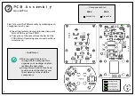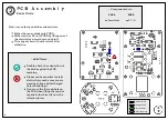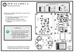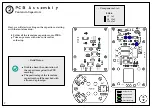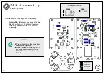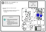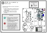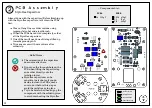
Ground Pin
PCB A
Ground Pin
PCB B
~ Components List ~
PCB Assembly
Ground Pins
2
Previous Steps
Ground Pins
Solder Joints
Components
Now is a good time to sort
through all the components to
organize your workspace before
tackling the next steps.
Using a three-band or four-band
resistor color code chart, assess
the resistance value of all the
components.
~ Build Notes ~
5
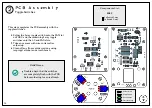
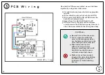
First, let's start the PCB assembly by soldering each
component one by one:
Insert the isolation turrets into insertion point
GG on PCB A and G on PCB B.
Trim some of the excess from the back of the
PCB while still mainting some room to solder a
wire later on.


