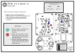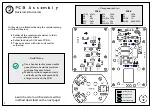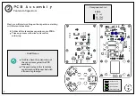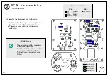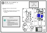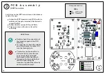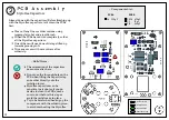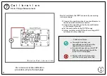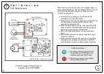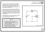
XLR Wiring
6
20
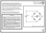
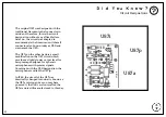
A little history of the U87 circuit
designations on the next page.
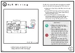
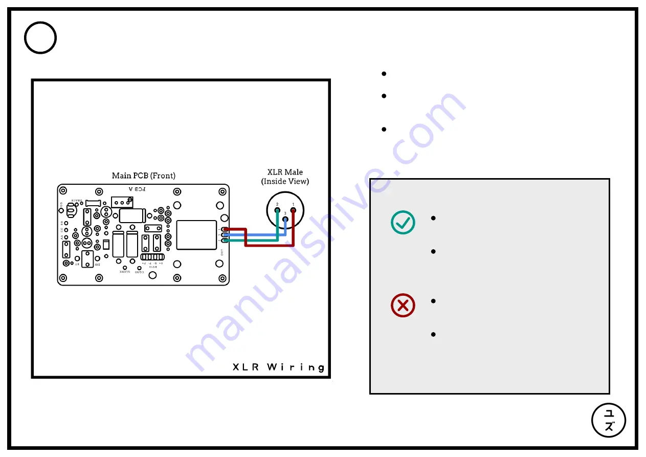
Finally, let's wrap up the main microphone assembly
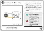
before calibration by wiring up the XLR connector:
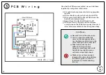
Wire Pin 1 of the XLR to 1 of PCB A, Pin 2 to 2 and
Pin 3 to 3.
Secure PCB C onto the top of the microphone
body by using three M2 x 6mm standoffs and
three M2 x 12mm screws.
Secure PCB A and B to the sides of the
microphone body by using eight M2 x 4mm
screws with PCB A facing the front of the
microphone along with the pattern switch.
Make sure you leave enough
length to the wires if trimming
any excess.
If you want to remove the XLR
inset from the microphone body
for easier soldering, rememeber
to twist the flathead screw in the
opposite direction than usual.
Make sure to twist the wires
together as tighlty as possible to
prevent any noise.
You can choose to solder the
wires on the component side or
use the hole provided to run the
wires through to the solder side.
~ Build Notes ~

