background image

YO AgriBox

User guide

v1.3

page 23/30

Connecting node with network

The LoRaWAN architecture requires a configured Gateway and Network Server. We’ll go through an
example in our recommended Yosensi Management Platform software.

Yosensi Management Platform configuration

Before you can make the node visible, you’ll need an

organization

and an

application

. The

organization is your own space, at the highest level of IoT systems management (like the root
directory in operating systems). It can be created only by Yosensi staff, and all clients using Yosensi
Management Platform have one created for them by default. In case of any questions, you can find us
at

[email protected]

. The application is a representation of each system and, together with the

node definitions, is created by customers. The basic integration of a node into the Yosensi
Management Platform is described below. Nodes can be added manually or via Bluetooth.

NOTE

A subscription is needed to use Yosensi Management Platform. Contact us on

[email protected] for more information and pricing.

Adding a node manually

Yosensi Management Platform integration instructions:

1. Log in to

app.yosensi.io

.

2. You’ll see the default organization view. To switch to another organization, click on the user

avatar in the right top corner and select ‘Switch Organization’.

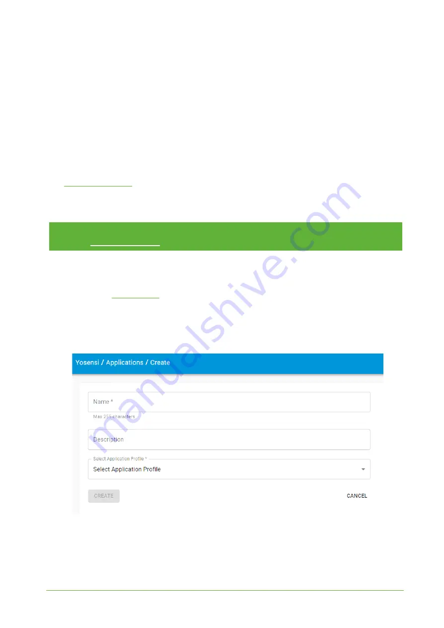
3. To create a new application, press the bottom right ‘+’ button. Fill in the ‘Name’ and

‘Description’ fields and select an ‘Application Profile’, which is the region definition.

Figure 20

Application creation form.

www.yo

sensi

.

io

Содержание YO AgriBox

Страница 1: ...YO AgriBox User guide v1 3...

Страница 2: ...ith firmware 3 5 0 added new device parameter with description soil type Changed instructions of connecting node with network due to release of Yosensi configuration web tool Checking OTAA and ABP key...

Страница 3: ...ondition 10 Installation 11 Package contents 11 Safety precautions 11 Installation guide 12 Operation 15 IoT system components 15 Device configuration 16 Configurable parameters 16 Parameters descript...

Страница 4: ...nd maintain optimum growing conditions for plants Figure 1 Device top view Device sticker placed on the right side of the device enclosure contains information about model version LoRaWAN region and 3...

Страница 5: ...ectly power and memory LoRaWAN communication failed to receive an acknowledgement from LoRaWAN Server within specified timeout Single flash White LoRaWAN communication LoRaWAN frame sent confirmation...

Страница 6: ...Figure 3 Dimensions of the device PHYSICAL SPECIFICATION Dimensions Height 42 mm Width 88 mm Depth 64 mm Colour Light grey Mounting method Horizontal Vertical can be screwed to the wall Enclosure mate...

Страница 7: ...Placement Indoor use Power supply 3 x LR6 AA battery 3 x 1 5 V Power consumption Maximum 120 mA DC 4 5 V DC Measured values MEASUREMENT RANGES Parameter Measurement range Accuracy Volumetric water con...

Страница 8: ...ontent This value measures soil moisture content Measurements are given in percentage value Accuracy depends on the correct sensor installation Figure 4 Volumetric water content chart probe 1 Figure 5...

Страница 9: ...l Temperature and relative internal humidity Temperature and relative humidity are measured by sensors placed inside the device enclosure These measurements can be used to monitor if the device is wor...

Страница 10: ...mplary chart Battery condition Battery voltage is used to monitor its condition to spot anomalies like sudden drop or its current condition based on voltage drop over time in comparison to initial vol...

Страница 11: ...may cause damage The equipment should be kept in a controlled environment CAUTION Batteries are at risk of exploding if incorrectly replaced Replace only with the same or equivalent type as recommende...

Страница 12: ...ay flood the device Installation guide 1 Unscrew the device remove 4 screws from the enclosure 2 Unscrew the cable gland nut and remove the cap Figure 10 Device with removed top cover and PG7 cap mark...

Страница 13: ...corresponding slot in the connector brown wire GND selected channel marked with symbol green wire OUT selected channel marked with symbol Connect the white cable VCC to the 3 3 V socket Tighten the c...

Страница 14: ...several possibilities of sensor installation Figure 14 shows the measuring probes can be completely buried and can be placed at different depths in the soil Soil moisture can be measured with one two...

Страница 15: ...way 2 Gateway device similar to routers equipped with a LoRa concentrator that receives LoRa packets and send them to the Internet connected server 3 Server in most cases a cloud based service where d...

Страница 16: ...etooth settings device dynamic individual configuration for a specific device this section s structure differs for each device Sample configuration file for the YO Agribox device info devmodel LNAG fw...

Страница 17: ...EUI Extended Unique Identifier 8 B HEX predefined R W appeui Application EUI 8 B HEX predefined R W appkey Application Key 16 B HEX predefined R W trials Join request trials 1 9 3 R W lorawan abp dev...

Страница 18: ...eys these parameters are generated using multiple IDs specific to the particular MCU and are unique for each device they can be changed if needed interval determines the interval of sending broadcast...

Страница 19: ...al measinterval by using downlink Information about changing parameter will be sent from server via gateway when Example of downlink message must include Prefix 0x03 Measurement index 0x00 Data up to...

Страница 20: ...11 7 MHz channels 40 47 6 Sub band 7 911 9 913 3 MHz channels 48 55 7 Sub band 8 915 5 914 9 MHz channels 56 63 8 AU915 Sub band 1 915 2 916 6 MHz channels 0 7 1 2 R W Sub band 2 916 8 918 2 MHz chann...

Страница 21: ...oad the device parameters Update firmware here you can update the firmware to version 3 4 0 and newer Recover device this section restores the firmware of the device This button helps if you lose the...

Страница 22: ...at you are in the correct organization Alternatively you can also scan the QR code placed on the node It will redirect you right to the device details 3 After selecting the device go to the configurat...

Страница 23: ...nsi io The application is a representation of each system and together with the node definitions is created by customers The basic integration of a node into the Yosensi Management Platform is describ...

Страница 24: ...tion appkey All device identifiers are provided by Yosensi Support when you order the nodes Select a model that is compatible with your device this choice affects the number of charts and data source...

Страница 25: ...ode configuration Click on the link in the Node Name column Go to the KEYS tab and switch LoRa Type from OTAA to ABP and fill in the blank spaces then press update The identifiers Device Address devad...

Страница 26: ...ver receives data from the device you ll notice that the Last Seen column NODES LIST tab status changes from never to a few seconds ago 7 Open charts by clicking on the OPEN button in Dashboard column...

Страница 27: ...Dashboard columns or by entering the node s DETAILS tab Node Name column link and clicking CHARTS Payload description If you want to connect to your own server it is necessary to decode the specific...

Страница 28: ...V val 1277 1277 mV val 1278 1278 mV val 0 0 mV Fifth measurement soil moisture probe 1 0x66 0x00 0x11 0x00 0x1E 0x90 type 25 prec 2 md s 0 addr_len 0 meas_len 2 addr 0 val 7824 78 24 Sixth measurement...

Страница 29: ...YO AgriBox User guide v1 3 page 29 30 Compliance statements www yosensi io...

Страница 30: ...YO AgriBox User guide v1 3 page 30 30 www yosensi io...

Отзывы: