background image

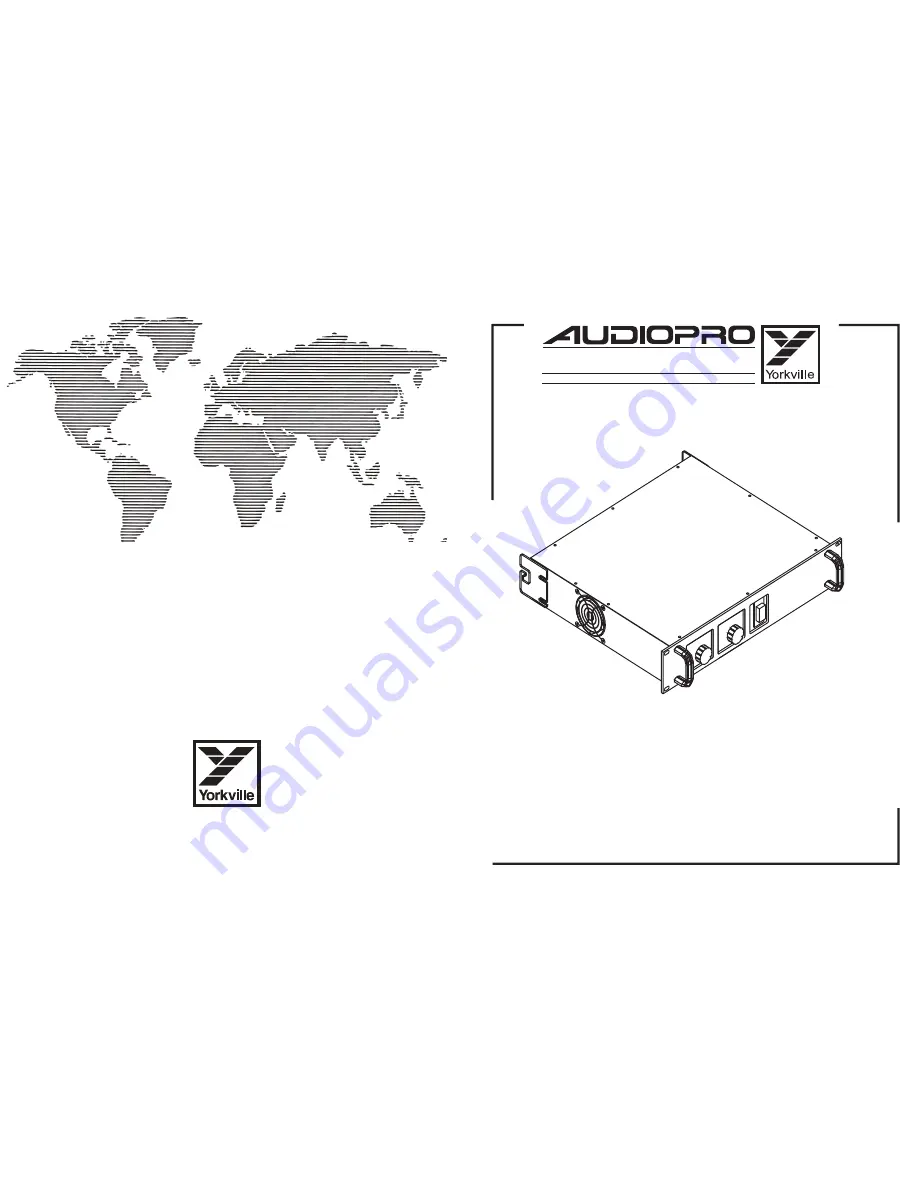
SERVICE MANUAL

3

400

HIGH  EFFICIENCY  STEREO  POWER  AMPLIFIER

U.S.A.

Yorkville Sound Inc.

4625 Witmer Industrial Estate

Niagara Falls, New York

14305 USA

Voice: (716) 297-2920

Fax: (716) 297-3689

WORLD HEADQUARTERS

CANADA

Yorkville Sound

550 Granite Court
Pickering, Ontario

L1W-3Y8 CANADA

Voice: (905) 837-8481

Fax: (905) 837-8746

Quality and Innovation Since 1963

Printed in Canada

Содержание Audiopro 3400

Страница 1: ...Inc 4625 Witmer Industrial Estate Niagara Falls New York 14305 USA Voice 716 297 2920 Fax 716 297 3689 WORLD HEADQUARTERS CANADA Yorkville Sound 550 Granite Court Pickering Ontario L1W 3Y8 CANADA Voice 905 837 8481 Fax 905 837 8746 Quality and Innovation Since 1963 Printed in Canada ...

Страница 2: ...r as marked on the unit This unit has a polarized plug Do not use with an extension cord or receptacle unless the plug can be fully inserted Precau tions should be taken so that the grounding scheme on the unit is not defeated Hazards Do not place this product on an unstable cart stand tripod bracket or table The product may fall causing serious personal injury and serious damage to the product Us...

Страница 3: ...fier U2 The DC offset forms a current through R54 R14 and is blocked by C5 giving a DC offset correction gain of 1 The activity L E D function is a simple charge pump circuit with a transistor that redirects a constant current path through the activity L E D 3 SHUTDOWN CIRCUIT The last circuit on board M1011A is the shutdown relay and its associated drive circuitry The relay circuit has two possib...

Страница 4: ...5V across R12 Q1 will turn off slightly causing Q5 to increase its source current The circuit reaches a point of equilibrium with approximately 0 5V across R12 Because all output devices are not identical and base emitter voltages vary some adjustment must be available to slightly adjust the 0 5V across R12 This is accomplished with RT1 RT1 causes Q1 to turn on slightly more or less resulting in Q...

Страница 5: ...y using an oscilloscope to measure differentially across R52 and R53 The conditions of the measurement are contained on the diagram During current limit when Q9 turns on it reduces the voltage across R42 R42 is in series with a 16 volt zener ZD7 and is also in parallel with the junction of Q8 Q8 is normally saturated by the current that flows through R20 ZD7 R42 and R22 When Q9 reduces the voltage...

Страница 6: ... Q34 The maximum fan voltage is 20 5 VDC ZD14 and R120 R121 and R122 provide a current limiting function Figure 4 shows the current throught these resistors when there is 12VDC across the fan Thermal Shutdown Circuit Test point 7 in the fan circuit is the measuring point for the shutdown voltage As the temperature sensing thermistors that control the fan circuit heat up the voltage on test point 7...

Страница 7: ... channels are reversed the amp will stay in protect mode with the red protect LED staying on or sampling on and off 11 SPECIFICATIONS POWER All values are in WATTS at 1KHz except FTC 20Hz 20KHz Measurements made with regulated 120 VAC sine wave at line cord All values are rounded down to the nearest 25 watts BURST AVERAGE Measured as a 2 cycle burst at 1KHz 8 1 duty Continuous measurements may req...

Страница 8: ...2 TO92 NPN TRANS T R 4 3893 AAVID HEATSINK 5811B 2 4777 1 4W 21K5 1 T R RES 2 5114 MPSA92 TO92 PNP TRANS T R 5 3894 AAVID 5972 B H S W TAB B O 4 4832 1 4W 22K 5 T R RES 1 6854 2N6517 TO92 NPN TRANS 2 3501 B52200F006 COMP WASH 4 SMALL 13 4833 1 4W 27K 5 T R RES 6 5105 MPSA13 TO92 NPN DARLINGTONT R 1 3750 VINYL CAP SC 0 500 BLACK 1 2 1 4840 1 4W 33K 5 T R RES 6 5106 MPSA63 TO92 PNP DARLINGTONT R 3 3...

Страница 9: ...7B 4K7 R46B 1K R45B 1K R44B 7K5 R42B 7K5 R38B MPSA92 Q13B MPSA42 Q12B 7K5 R41B 7K5 R39B 10p 300V C22B D16B D15B D13B D14B 220R R40B 22u 16v C19B 22u 16v C18B 10u 160V C28B 10u 160V C27B NJM431 2V5 Q21B 150R R64B 150R R57B 10R R59B NJM431 2V5 Q21A NJM431 2V5 Q20B 33K R67A 10R R66B 68K R70B 33K R69B BC560C E B C BC550C MJE2361T MJE5730 E C B MPSA92 C B E MPSA42 MPSA63 C B E MPSA13 A13 Q29 A63 Q28 GR...

Страница 10: ...C21B NJM431 2V5 Q20A 10 9 8 7 6 5 4 3 2 1 DESCRIPTION OF CHANGE VER DATE MODEL S D D D D D APR 08 97 DEC 02 94 JUN 22 94 V V V V V 2 50 2 40 2 30 N N N N N PC 5353_R60A_1 2W_220K 2W_220K AUG 05 98 2 60 PC 5528_Q16 A B REPLACE WITH TIP50 6891 Q20A B_Q21A B PC 4651_DEL_LD9 LD14_ADD_NJM431L PC 4529_BD651 BDX53C_BD652 BDX54C AP 3400 M1011A SCH_DATABASE_HISTORY BC550 Q17B BC560 Q14B 17K8 1 R56B 3K R43B...

Страница 11: ...4 TP3 TP2 TP1 NO NC C RE1 AROMAT_RELAY 3699 48V_COIL C43 220N 250V C42 220N 250V P2 25A10K PT 4400 P1 25A10K PT 4400 R99 R6 1 4W 330R R98 R6 1 4W 330R R124 R13 0 5W 1K5 E B Q11 PART FUNCTION BF872 D48 1N4004 ZD17 ZD1 10V C31 27P 1 _MW3 FUNCTION C32 27P Q28 A63 Q29 A13 Q38 Q5 MPSA92 Q36 Q6 2N5551 Q10 A63 Q5 A63 C17 47U 10V C9 47U 10V ZD2 4V7 ZD1 4V7 E B Q16B Q2 TIP50 Q8 BC550 Q6 BC560 Q7 BC550 Q9 B...

Страница 12: ...F872 D48 1N4004 ZD17 ZD1 10V C31 27P 1 _MW3 FUNCTION C32 27P Q28 A63 Q29 A13 Q38 Q5 MPSA92 Q36 Q6 2N5551 Q10 A63 Q5 A63 C17 47U 10V C9 47U 10V ZD2 4V7 ZD1 4V7 E B Q16B Q2 Q8 BC550 Q6 BC560 Q7 BC550 Q9 BC550 Q4 BC550 Q2 BC550 Q1 BC560 Q3 BC550 D36 BAV21 J19 J11 D5 4148 D11 4148 D49 1N4004 D12 4148 D6 4148 D8 4148 D7 4148 D10 4148 D46 4148 J21 D3 4148 D4 4148 D1 4148 D2 4148 RV1 100K C52 4U7 63V C10...

Страница 13: ... 1 2 33078 U2 6 5 7 NUTRIX BAL_IN JB4 1 3 2 S R T CH_A_IN NO_GOLD JB3 1 2 3 4 5 6 YORKVILLE NAME PCB VER MODELS SCH ISSUE TITLE DATE M1012 2 00 AP 3400 AUDIO PRO M1012A SCH SEP 19 94 INPUT_ _FILTER 0 00 16v 68n C15 16v 100n C16 16v 47n C18 16v 150n C19 17K8 1 R33 470R R16 OUT IN S1 4 5 6 16v 470n C17 4M7 R32 470R R34 T7 T6 T5 T4 T3 T8 T1 100n C23 100n C24 100n C21 100n C22 1K5 R18 1K5 R36 16v 6n8 ...

Страница 14: ... 40 C6 100N 40 40 C5 68N 40 40 C15 68N 40 40 C16 100N 40 40 C18 47N 40 40 C19 150N 40 40 C17 470N 40 40 C10 6N8 40 40 C20 6N8 40 40 J17 52 52 J18 52 52 JB3 UNBAL_IN_B 59 59 59 59 59 59 40 40 C1 470P 40 40 C2 470P 40 40 C3 100P 40 40 C4 100P 40 40 C14 100P 40 40 C13 100P 40 40 C12 470P 40 40 C11 470P 40 40 C23 100N 40 40 C24 100N 40 40 C21 100N 40 40 C22 100N 40 40 J7 52 52 LINEWIDTH GAUGE TP1 40 4...

Страница 15: ...V V V V V V V V 1 40 N N N N N N N N N PC 5444_R120 122_1 4W 1 2W AP3400 M1013A SCH_DATABASE_HISTORY WC10 EY12 EY9 YORKVILLE NAME PCB VER MODELS SCH ISSUE TITLE DATE M1013A AP 3400 M1013A SCH AUG 12 97 SUPPLY FAN_PCB 1 40 330u 80V C47 330u 80V C46 330u 80V C45 330u 80V C44 13AMP DB2 3 4 1 2 13AMP DB1 3 4 1 2 UI YSL 120VAC 1KVA TYPE_H TR1 4v7 500mW ZD14 27K R115 WHITE BLACK CHASSIS KILL GND GND GND...

Страница 16: ...00K RV6 100K RV5 13A 85C TB2 8A SW TB1 L1 MPSA06 EBC 2N5551 MJH11018 E C B YORKVILLE NAME PCB VER MODELS SCH ISSUE TITLE DATE M1013A 2 20 AP 3400E M1013AE SCH SEP 28 95 SUPPLY FAN_PCB 1 40 WC10 EY12 EY9 330u 80V C47 330u 80V C46 330u 80V C45 330u 80V C44 13AMP DB2 3 4 1 2 13AMP DB1 3 4 1 2 YSL 1288E 220 240VAC TR1 4v7 500mW ZD14 27K R115 BLUE CHASSIS KILL GND GND GND GND GND GND 78 78 78 18 RTSENS...

Страница 17: ... N N N N N N N N N N N N PC 49 PC 4576 PC 4529 AP 3000 M1013 PCB_DATABASE_HISTORY EY2 AC WHITE J25 J24 J21 J23 EY3 X F BLACK 20 19 18 17 16 15 14 13 12 11 10 9 8 7 6 5 4 3 2 1 DESCRIPTION OF CHANGE VER DATE MODEL S D D D D D D D D D D D D D D D D D NOV 24 95 SEP 20 94 MAY 26 94 V V V V V V V V V V V V V V V V V 2 30 2 21 2 20 N N N N N N N N N N N N N N N N N PC 49 PC 4576 PC 4609 AP 3400 M1013A P...

Страница 18: ...900 Q20 YS 6900 D4 4148 Q23 YS 6927 Q27 YS 6927 D15 MR854 D14 MR854 D13 MR854 D12 MR854 D21 MR854 D19 MR854 D18 MR854 D17 MR854 D16 MR854 D22 MR854 TP2 D23 MR854 ZD4 12V ZD3 3V C17 100N D26 4004 J19 ZD2 16V C6 330U 16V C7 330U 16V Q7 2N6517 C11 220N 250V Q30 TRIAC MAC224 4 DC_PROT J9 D25 4148 R62 3R9 2WATT TP4 D24 4004 TP5 TP7 TP6 TP8 TP9 TP10 TP1 J20 R21 2K2 R76 8K2 ZD6 3V ZD5 12V D5 4148 R77 470...

Страница 19: ...m the speaker output to test point 4 or 5 As you variac up also check these DC battery voltages to ensure that they both increase in voltage to approximately 14 or 14 vdc If the board looks OK after variacing up to 120vac then slowly turn up the bias RT1 trimpot to obtain 3 to 5 millivolts of bias voltage on test points 8 and 9 Now power down the board connect MC1 to circuit board M1011 and variac...

Страница 20: ...nents to perform the Quick Fix to a M1002 or M1002A board It should be understood that the person using this procedure knows how to test resistors diodes and transistors to determine if they are defective This procedure is not intended to be a substitute for one s lack of electronic capability Before starting look at the board for repair and locate the version number It is very important that you ...

Страница 21: ...n version 9 and higher add only in versions 9 and lower that may have been added to the component side of the board along with a series 0 5 ohm resistor Refer to figure 1 Figure 1 4 Rotate the trim pot RT1 fully counter clockwise as in figure 2 Inspect and replace any resistors that look burnt Measure all of the resistor values coloured YELLOW on the assembly drawing The value that you measure may...

Страница 22: ...is 0 1 ohm your ohmmeter will measure the higher series resistance of the test leads if the resistor is OK If the resistor is damaged your ohmmeter will read a very high resistance an open circuit Replace any damaged resistors 8 Measure the output TO 3 transistors Q13 to Q28 to determine if any are damaged Mark any damaged transistors with a marking pen 9 Replace any output transistors that you ha...

Страница 23: ..._HISTORY TP4 D24 4004 TP5 TP7 TP6 TP8 TP9 TP10 TP1 J20 R21 2K2 R76 8K2 ZD6 3V ZD5 12V D5 4148 R77 470K R23 4K7 R24 220K R25 220K R42 4K7 R22 3K R75 150K ZD7 18V D28 4148 D27 4148 J1 R51 220R0 R35 1K J4 R33 1W_FP 1R R49 1WATT 0 R47 C27 22N G S Q6B Q1 MTP2P50E ZD1 16V C21 10U 16V D10 BAV21 20 19 18 17 16 15 14 13 12 11 10 9 8 7 6 5 4 3 2 1 DESCRIPTION OF CHANGE VER DATE MODEL S D D D D D D JAN 28 98...

Страница 24: ...RE D Y E L L O W BLU A C W HIT E FAN L1 W C7 C44 C45 C46 C47 EY7 EY10 EY11 EY5 E Y12 W C 8 T JH 1 WC10 W C4 W C3 EY13 W C1 WC 11 W C6 EY8 EY6 EY9 RV5 100K EY2 EY3 EY4 C55 4N7 250V EY14 C53 22N 250V C54 22N 250V RV6 100K 1289 AP 3400CE XFMR WIRING NOV 13 95 SHOWN WIRED FOR 230V ...

Страница 25: ...RE D Y E L L O W BLU A C W HIT E FAN L1 W C7 C44 C45 C46 C47 EY7 EY10 EY11 EY5 E Y12 W C 8 T JH 1 WC10 W C4 W C3 EY13 W C1 WC 11 W C6 EY8 EY6 EY9 RV5 100K EY2 EY3 EY4 C55 4N7 250V EY14 C53 22N 250V C54 22N 250V RV6 100K 1289 AP 3400CE XFMR WIRING NOV 13 95 SHOWN WIRED FOR 245V ...

Отзывы: