JOHNSON CONTROLS
59
SECTION 5 – MAINTENANCE
FORM 160.81-NOM1
ISSUE DATE: 10/3/2020
5
water loop. This can cause refrigerant in the oil
separator to condense, creating a liquid level (oil
and refrigerant mixture) that exceeds the top of
the upper sight glass. When the chiller motor is
not running, a qualified technician should confirm
that the oil heater is in proper working condition
and is energized. If it is the first startup for the
cooling season, the technician should confirm the
oil heater has been energized for at least 24 hours
prior to start up. During start-up, the chiller should
be manually unloaded until a discharge superheat
temperature (displayed on the "COMPRESSOR
SCREEN" of the OptiView control center) of
18ºF (-8ºC) or greater is maintained and liquid
level drops below the top of the upper sight glass
on the oil separator. The chiller should continue to
be held in a "part-load" operation until the foam-
ing in the oil separator is minimized. The chiller
can then be returned to "automated" slide valve
position or "load control" to meet the cooling load
requirements.
Operation
1. Oil should be visible in both sight glasses of the oil
separator (oil level above the upper sight glass):
If the chiller operates in a low discharge superheat
(refer to
this manual) condition for an extended period of
time refrigerant can again condense in the oil sep-
arator. The chiller should be unloaded and held in
a slide valve position that allows the discharge su-
perheat to increase above 18ºF (-8ºC). The chiller
should continue to be held in a slide valve position
until the level drops below the top of the upper
sight glass and foaming is minimized. The chiller
can then be loaded normally as the building/pro-
cess load requires.
2. Oil level cannot be seen in either sight glass on the
oil separator (oil level is below lower sight glass):
If no oil level is in either sight glass (oil level
below lower sight glass) a problem may exist
with the oil return system. A qualified technician
should add only enough oil to create a visible lev-
el in the bottom of the lower sight glass. Start the
chiller and run a load condition greater than 65%
full load amps [FLA] but less than 80% FLA for a
minimum of 1 hour and observe the oil level. The
oil level should become visible in either the bot-
tom or top sight glass depending on conditions. A
qualified technician should then remove the ap-
proximate amount added to start the chiller. Refer
to
in this
manual.
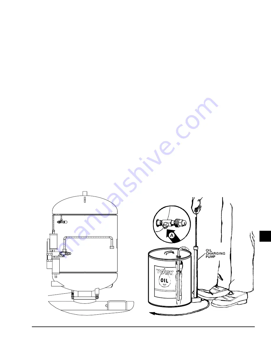
FIGURE 23 -
CHARGING OIL
LD08912
LD07125
OIL
CHARGING
VALVE


