JOHNSON CONTROLS
13
SECTION 1 - SHIPPING AND REASSEMBLY
FORM 160.75-N3
ISSUE DATE: 04/15/2019
1
5. Reconnect motor power leads in the Variable
Speed Drive to T1, T2, and T3 terminals and
torque to 18-20 Ft-lbs. per the labels in the VSD.
6.
Reconnect motor winding thermistor shielded ca-
ble conductors in the Variable Speed Drive at TB4
(refer to
Wiring Diagrams - Field Connections -
Remote Mounted MV SSS (Form 160.75-PW2)
.
7. Reconnect all unit wiring and harnesses (refer to
Wiring Diagrams - Field Connections - Remote
Mounted MV SSS (Form 160.75-PW2)
.
8. Pressure test the unit.
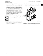
Relief valves must be plugged or capped
(refer to Unit Operations and Mainte-
nance, Form 160.75-O1).
9.
FORM 9
-
Remove nitrogen and charge unit with
refrigerant (refer to
Unit Operations and Mainte-
nance (Form 160.75-O1)
.
10.
All Units –
Complete installation and finally level
the unit (refer to
Installation - Unit (Form 160.75-
N1)
.
LD16730
Lifting
Holes
Lifting
Holes
65°
Min.
65°
Min.
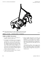
FIGURE 5 -
VARIABLE SPEED DRIVE RIGGING


