SECTION 2 - PRODUCT DESCRIPTION
FORM 155.32-ICOM2.EN.UL
ISSUE DATE:1/10/2018
20
JOHNSON CONTROLS
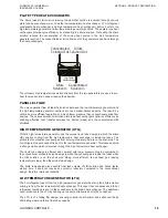
CONDENSER
The cooling water from the absorber section enters into the condenser section. This helps
condense the refrigerant vapors produced in the LTG as well as the condensed refrigerant
from the drain heat exchanger. The liquid refrigerant is then sent back to the evaporator
section through a U-pipe (liquid seal). This completes the cooling cycle.
CRYSTALLIZATION
All absorption chiller-heaters that use LiBr and water as the solution/refrigerant pair are
subject to crystallization. This is due to the fact that some areas of the unit operate with
solution liquid concentration levels that are only possible at higher than the normal ambient
temperature surrounding the unit. For example, the solution concentration in the generator
of a single effect absorption unit is typically 64.3% LiBr by weight. LiBr begins to crystallize
at 110°F (43.3°C).
Crystallization is the result of the LiBr solution temperature going too low or the
concentration too high. The LiBr solution becomes like slush. At this point the LiBr solution
cannot absorb any more water and will start to solidify (crystallize).
Crystallization will occur in the solution heat exchanger and sometimes even in the
generator. It will also happen in pipes not well insulated where room temperature can affect
the solution moving through the pipes.
You can prevent crystallization by making sure you keep the solution temperature high and
the concentration at the optimum percentage (64%).
Since the solution temperature in the generator is normally high enough in most load
conditions, no crystallization will occur as long as the higher solution temperatures are
maintained. Special measures do have to be taken before the unit is shut down so that the
solution is sufficiently diluted in all areas of the unit to prevent crystallization during the off
cycle, since the solution temperature will eventually equal the surrounding ambient
temperature. All units employ some sort of dilution cycle, which fulfills this requirement.
As long as the unit is allowed to dilute itself during an orderly shutdown sequence, the unit
should be able to sit idle at fairly low plant room ambient temperatures for extended periods
of time without any threat of crystallization. Typically, after a dilution cycle, the average
solution concentration within the chiller-heater will be below 45% LiBr by weight and will
have no tendency to crystallize at normal ambient temperatures.
WHY DOES CRYSTALLIZATION OCCUR?
The most common reason for crystallization is due to power failures. If a chiller-heater is
running at full load and power is interrupted for a sufficient length of time, the concentrated
solution in the high side of the unit (Condenser/Generator Section) will eventually cool
down. Since no dilution cycle was performed, the solution concentration in some areas of
the unit may still be relatively high. If the temperature of this concentrated solution is
allowed to fall low enough, the solution will reach its crystallization point. Plant room
temperature, insulation quality, and the solution concentration all play a part in determining
how long it will take before the unit will crystallize. See
information on water quality control and crystallization. The Duhring Diagram / PTX Chart
shows the specific temperatures and pressures of the crystallization area. See
the
Diagram / PTX Chart (°F) on page 156
and
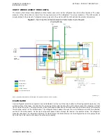
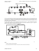
LD19980_a6
Condenser
Cooling
Water
Outlet
Condensed
Refrigeration
Содержание YHAU-CGH
Страница 14: ...FORM 155 32 ICOM2 EN UL ISSUE DATE 1 10 2018 14 JOHNSON CONTROLS THIS PAGE INTENTIONALLY LEFT BLANK...
Страница 38: ...FORM 155 32 ICOM2 EN UL ISSUE DATE 1 10 2018 38 JOHNSON CONTROLS THIS PAGE INTENTIONALLY LEFT BLANK...
Страница 55: ...FORM 155 32 ICOM2 EN UL ISSUE DATE 1 10 2018 JOHNSON CONTROLS 55 THIS PAGE INTENTIONALLY LEFT BLANK...
Страница 57: ...FORM 155 32 ICOM2 EN UL SECTION 4 TECHNICAL DATA ISSUE DATE 1 10 2018 JOHNSON CONTROLS 57 LD27463...
Страница 59: ...FORM 155 32 ICOM2 EN UL SECTION 4 TECHNICAL DATA ISSUE DATE 1 10 2018 JOHNSON CONTROLS 59 LD27465...
Страница 61: ...FORM 155 32 ICOM2 EN UL SECTION 4 TECHNICAL DATA ISSUE DATE 1 10 2018 JOHNSON CONTROLS 61 LD27471...
Страница 63: ...FORM 155 32 ICOM2 EN UL SECTION 4 TECHNICAL DATA ISSUE DATE 1 10 2018 JOHNSON CONTROLS 63...
Страница 65: ...FORM 155 32 ICOM2 EN UL SECTION 4 TECHNICAL DATA ISSUE DATE 1 10 2018 JOHNSON CONTROLS 65 LD27477...
Страница 67: ...FORM 155 32 ICOM2 EN UL SECTION 4 TECHNICAL DATA ISSUE DATE 1 10 2018 JOHNSON CONTROLS 67 LD27479...
Страница 69: ...FORM 155 32 ICOM2 EN UL SECTION 4 TECHNICAL DATA ISSUE DATE 1 10 2018 JOHNSON CONTROLS 69 LD27475...
Страница 160: ...FORM 155 32 ICOM2 EN UL ISSUE DATE 1 10 2018 160 JOHNSON CONTROLS THIS PAGE INTENTIONALLY LEFT BLANK...
Страница 170: ...FORM 155 32 ICOM2 EN UL ISSUE DATE 1 10 2018 170 JOHNSON CONTROLS THIS PAGE INTENTIONALLY LEFT BLANK...
Страница 172: ...FORM 155 32 ICOM2 EN UL ISSUE DATE 1 10 2018 172 JOHNSON CONTROLS THIS PAGE INTENTIONALLY LEFT BLANK...
Страница 181: ...FORM 155 32 ICOM2 EN UL APPENDIX 1 CHECKLIST ISSUE DATE 1 10 2018 JOHNSON CONTROLS 181 NOTES...

