SECTION 5 - COMMISSIONING
FORM 155.32-ICOM2.EN.UL
ISSUE DATE:1/10/2018
88
JOHNSON CONTROLS
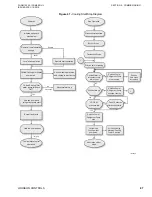
Figure 42 -
Direct Fire Sequential Flowchart
NOTES:
1. Be sure to implement sequential operation of the chilled water pump, the cooling water pump, and the hot water pump from the chiller.
2. If there is only one air conditioner, secure interlock for the air conditioner operation (the part indicated by broken lines shown in the diagram above).
3. Implement sequential operation in such a way that when the chilled water pump stops, the cooling water pump, and the hot water pump also stop.
4. If the hot, chilled and cooling water system is the common system, you must install the isolation valve on the hot water, chilled water and cooling water inlet pipe entering the chiller, and
interlock these isolation valves with the chiller control panel. It is important for safe and reliable operation of the chiller as well as to prevent potential crystallization of LiBr solution and
freezing of the evaporator tubes.
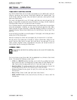
Figure 43 -
Stopping absorption chiller-Heater Direct Fire Flowchart
NOTES:
1. Verify that the air conditioner has stopped after the chiller dilution operation is complete. Otherwise, the chiller may become damaged due to freezing of the chilled water and/or
crystallization of the solution.
2. The installation and interlocking of these valves with the chiller control panel is mandatory for safe and reliable operation of the chiller and to prevent potential crystallization of LiBr solution
and freezing of the evaporator tubes.
LD22953
Chiller - Heater
Chilled/Hot Water
Pump
Sequential
Operation
AND
Air Conditioner
Cooling Water Pump
Cooling Tower
AND
Interlock
Sequential
Operation
(2)
(3)
Sequential
Operation
Interlock
Other interlocks, including earthquake sensor, abnormal room temperature sensor, and so on.
Sequential
Operation
LD22954
Not completed
AND
Chiller - Heater
dilution operation
begins
Chiller-Heater dilution
operation completed
Stop the chiller-heater
Completed
Chilled/hot water pump
and air conditioner stop
Stop the air
conditioner
Содержание YHAU-CGH
Страница 14: ...FORM 155 32 ICOM2 EN UL ISSUE DATE 1 10 2018 14 JOHNSON CONTROLS THIS PAGE INTENTIONALLY LEFT BLANK...
Страница 38: ...FORM 155 32 ICOM2 EN UL ISSUE DATE 1 10 2018 38 JOHNSON CONTROLS THIS PAGE INTENTIONALLY LEFT BLANK...
Страница 55: ...FORM 155 32 ICOM2 EN UL ISSUE DATE 1 10 2018 JOHNSON CONTROLS 55 THIS PAGE INTENTIONALLY LEFT BLANK...
Страница 57: ...FORM 155 32 ICOM2 EN UL SECTION 4 TECHNICAL DATA ISSUE DATE 1 10 2018 JOHNSON CONTROLS 57 LD27463...
Страница 59: ...FORM 155 32 ICOM2 EN UL SECTION 4 TECHNICAL DATA ISSUE DATE 1 10 2018 JOHNSON CONTROLS 59 LD27465...
Страница 61: ...FORM 155 32 ICOM2 EN UL SECTION 4 TECHNICAL DATA ISSUE DATE 1 10 2018 JOHNSON CONTROLS 61 LD27471...
Страница 63: ...FORM 155 32 ICOM2 EN UL SECTION 4 TECHNICAL DATA ISSUE DATE 1 10 2018 JOHNSON CONTROLS 63...
Страница 65: ...FORM 155 32 ICOM2 EN UL SECTION 4 TECHNICAL DATA ISSUE DATE 1 10 2018 JOHNSON CONTROLS 65 LD27477...
Страница 67: ...FORM 155 32 ICOM2 EN UL SECTION 4 TECHNICAL DATA ISSUE DATE 1 10 2018 JOHNSON CONTROLS 67 LD27479...
Страница 69: ...FORM 155 32 ICOM2 EN UL SECTION 4 TECHNICAL DATA ISSUE DATE 1 10 2018 JOHNSON CONTROLS 69 LD27475...
Страница 160: ...FORM 155 32 ICOM2 EN UL ISSUE DATE 1 10 2018 160 JOHNSON CONTROLS THIS PAGE INTENTIONALLY LEFT BLANK...
Страница 170: ...FORM 155 32 ICOM2 EN UL ISSUE DATE 1 10 2018 170 JOHNSON CONTROLS THIS PAGE INTENTIONALLY LEFT BLANK...
Страница 172: ...FORM 155 32 ICOM2 EN UL ISSUE DATE 1 10 2018 172 JOHNSON CONTROLS THIS PAGE INTENTIONALLY LEFT BLANK...
Страница 181: ...FORM 155 32 ICOM2 EN UL APPENDIX 1 CHECKLIST ISSUE DATE 1 10 2018 JOHNSON CONTROLS 181 NOTES...


