


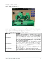

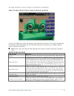


Variable Geometry Diffuser (VGD) setpoints screen
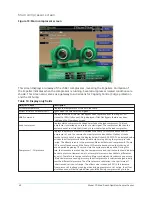
Figure 15: Variable Geometry Diffuser setpoints screen
The Variable Geometry Diffuser setpoints for VGD 1 and 2 are maintained on this screen. All
setpoints require a login access level of Service unless otherwise noted.
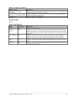
Table 30: Display only fields
Field/LED name
Description
Variable Geometry Diffuser 1: Stall
detector voltage
Displays the Stall Detector output voltage (x.xxVDC), as received by the Microboard.
Variable Geometry Diffuser 1: PRV
position
Displays the position of the Pre-Rotation Vanes over the range of 0% (fully closed) to
100% (fully open). Displayed as XXX until calibration procedure is performed by Service
Technician.
Variable Geometry Diffuser 1: VGD
position
Displays the position of the VGD over the range of 0% (fully closed) to 100%
(fully open). Displayed as XXX until calibration procedure is performed by Service
Technician.
Variable Geometry Diffuser 1: VGD
opening (LED)
Lights when an open signal is being applied to the VGD.
Variable Geometry Diffuser 1: VGD
closing (LED)
Lights when a close signal is being applied to the VGD.
Variable Geometry Diffuser 2: Stall
detector voltage
Displays the Stall Detector output voltage (x.xxVDC), as received by the Microboard.
Variable Geometry Diffuser 2: PRV
position
Displays the position of the Pre-rotation vanes over the range of 0% (fully closed) to
100% (fully open). Displayed as XXX until calibration procedure is performed by Service
Technician.
Variable Geometry Diffuser 2: VGD
position
Displays the position of the VGD over the range of 0% (fully closed) to 100%
(fully open). Displayed as XXX until calibration procedure is performed by Service
Technician.
Variable Geometry Diffuser 2: VGD
opening (LED)
Lights when an open signal is being applied to the VGD.
Variable Geometry Diffuser 2: VGD
closing (LED)
Lights when a close signal is being applied to the VGD.
49
Model YD Mod D with OptiView Control Center
Содержание YD Mod D
Страница 2: ...2 Model YD Mod D with OptiView Control Center...
Страница 8: ...Nomenclature Model YD Mod D with OptiView Control Center 8...
Страница 17: ...Figure 2 Chiller operation flow chart 17 Model YD Mod D with OptiView Control Center...
Страница 18: ...Figure 2 Chiller operation flow chart Model YD Mod D with OptiView Control Center 18...
Страница 19: ...Figure 2 Chiller operation flow chart 19 Model YD Mod D with OptiView Control Center...
Страница 20: ...Figure 2 Chiller operation flow chart Model YD Mod D with OptiView Control Center 20...
Страница 21: ...Figure 2 Chiller operation flow chart 21 Model YD Mod D with OptiView Control Center...
Страница 22: ...Figure 2 Chiller operation flow chart Model YD Mod D with OptiView Control Center 22...
Страница 150: ...Figure 57 Sample printout status Model YD Mod D with OptiView Control Center 150...
Страница 151: ...Figure 57 Sample printout status 151 Model YD Mod D with OptiView Control Center...
Страница 152: ...Figure 58 Sample printout setpoints Model YD Mod D with OptiView Control Center 152...
Страница 153: ...Figure 58 Sample printout setpoints 153 Model YD Mod D with OptiView Control Center...
Страница 154: ...Figure 59 Sample printout schedule Model YD Mod D with OptiView Control Center 154...
Страница 155: ...Figure 60 Sample printout sales order 155 Model YD Mod D with OptiView Control Center...
Страница 156: ...Figure 61 Sample printout history Model YD Mod D with OptiView Control Center 156...
Страница 157: ...Figure 61 Sample printout history 157 Model YD Mod D with OptiView Control Center...
Страница 159: ...Figure 64 Sample printout custom screen report 159 Model YD Mod D with OptiView Control Center...