


207
JOHNSON CONTROLS
SECTION 9 – SERVICE AND TROUBLESHOOTING
FORM 150.67-NM1
ISSUE DATE: 4/28/2017
9
CHECKING INPUTS AND OUTPUTS
Digital Inputs
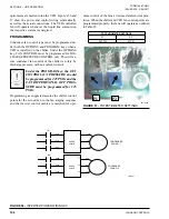
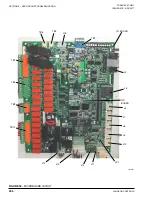
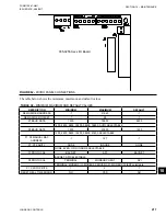
Refer to the unit wiring diagram. All digital inputs are
connected to J13-1 of the I/O board. The term “digital”
refers to two states – either ON or OFF. As an example,
when the flow switch is closed, 30VDC will be applied
to J13, pin 5 (J13-5) of the I/O board. If the flow switch
is open, 0VDC will then be present at J13-5.
Pin 1 of J13 is an
unregulated
30VDC
source
used to
supply the DC voltage to the various user contacts, unit
switch, flow switch, etc. This DC source is factory wired
to CTB1, terminal 13. Any switch or contact used as a
digital input would be connected to this terminal, with
the other end connecting to its respective digital input on
the microboard. Any time a switch or contact is closed,
30VDC would be applied to that particular digital input.
Any time a switch or contact is open, 0VDC would be
applied to that particular digital input.
Typically, voltages of 24 to 36VDC could be measured
for the DC voltage on the digital inputs. This voltage is
in reference to ground. The unit case should be suffi-
cient as a reference point when measuring digital input
voltages.
Analog Inputs – Temperature
Refer to the unit wiring diagram. Temperature inputs
are connected to the microboard on plug J6. These ana-
log inputs represent varying DC signals corresponding
to varying temperatures. All voltages are in reference
to the unit case (ground). Following are the connec-
tions for the temperature sensing inputs:
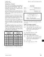
Outside Air Sensor
J6-6 = +5VDC regulated supply to sensor.
J6-9 = VDC input signal to the microboard.
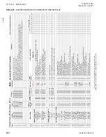
See Table 34 for voltage readings that correspond to
specific outdoor temperatures.
J6-3 = drain (shield connection = 0VDC) Return
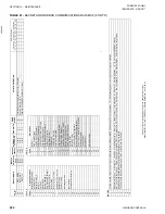
TABLE 34 -
OUTDOOR AIR SENSOR TEMPERA-
TURE/VOLTAGE / CORRELATION
TEMP °F
VOLTAGE
(SIGNAL INPUT
TO RETURN)
TEMP °C
0
0.7
-18
5
0.8
-15
10
0.9
-12
15
1.0
-9
20
1.1
-7
25
1.2
-4
30
1.4
-1
35
1.5
2
40
1.7
4
45
1.8
7
50
2.0
10
55
2.2
13
60
2.3
16
65
2.5
18
70
2.6
21
75
2.8
24
80
2.9
27
85
3.1
29
90
3.2
32
95
3.4
35
100
3.5
38
105
3.6
41
110
3.7
43
115
3.8
46
120
3.9
49
125
4.0
52
130
4.1
54
Содержание YCAL0019
Страница 4: ...JOHNSON CONTROLS 4 FORM 150 67 NM1 ISSUE DATE 4 28 2017 THIS PAGE INTENTIONALLY LEFT BLANK...
Страница 14: ...JOHNSON CONTROLS 14 FORM 150 67 NM1 ISSUE DATE 4 28 2017 THIS PAGE INTENTIONALLY LEFT BLANK...
Страница 69: ...69 JOHNSON CONTROLS SECTION 5 TECHNICAL DATA FORM 150 67 NM1 ISSUE DATE 4 28 2017 5 5...
Страница 71: ...71 JOHNSON CONTROLS SECTION 5 TECHNICAL DATA FORM 150 67 NM1 ISSUE DATE 4 28 2017 5 5...
Страница 127: ...127 JOHNSON CONTROLS SECTION 5 TECHNICAL DATA FORM 150 67 NM1 ISSUE DATE 4 28 2017 5 5 DIMENSIONS YCAL0052 SI CONT D...
Страница 129: ...129 JOHNSON CONTROLS SECTION 5 TECHNICAL DATA FORM 150 67 NM1 ISSUE DATE 4 28 2017 5 5 DIMENSIONS YCAL0056 SI CONT D...
Страница 191: ...191 JOHNSON CONTROLS SECTION 8 UNIT OPERATION FORM 150 67 NM1 ISSUE DATE 4 28 2017 8 Figure 48 WIRING LD11799A...
Страница 202: ...JOHNSON CONTROLS 202 FORM 150 67 NM1 ISSUE DATE 4 28 2017 SECTION 8 UNIT OPERATION THIS PAGE INTENTIONALLY LEFT BLANK...
Страница 229: ...229 JOHNSON CONTROLS SECTION 10 MAINTENANCE FORM 150 67 NM1 ISSUE DATE 4 28 2017 NOTES...


