YORK INTERNATIONAL
14
INSTALLATION
Close-Coupled Models
1. Place the number of shims originally required on
each motor mounting rail.
2. Lift motor to the proper location and push motor
carefully against the compressor motor adapter.
3. Line up holes in the face of the motor with the holes
in the compressor motor adapter. Place the hex head
cap screws through the compressor motor adapter
and screw into the tapped holes on the motor, (but
do not fully tighten screws). (See Fig. 15)
4. Place the hex head cap screws and washers in holes
in motor feet. Make sure the motor is shimmed cor-
rectly. Place hex nuts on screws and tighten and
torque.
5. Tighten and torque screws holding motor-to-motor
adapter.
6. Assemble the coupling. Refer to Form 160.49-N4.
Open-Drive Models
1. Place the number of shims originally required on
each motor mounting channel.
2. Lift motor to its proper location on the motor mount-
ing channels. Fasten with cap screws, washers, and
hex nuts.
3. Assemble the coupling. Refer to Form 160.49-N4.
4. Re-assemble the coupling guard.
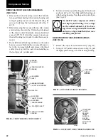
Before opening any part of the
compressor, the compressor must be
pumped down to atmospheric
pressure.
SHAFT SEALS
Shaft seals applied to these compressors are of two dif-
ferent designs. Original design compressors used a car-
bon ring cartridge type shaft seal. This design is shown in
Figs. 19 - 23; procedures for removal and installation are
shown on pages 14 & 15. Beginning approximately May
1998, compressors are equipped with a bellows-type shaft
seal. This seal is shown in Fig. 29; procedures for re-
moval and installation are shown on pages 16 & 17.
Removal (Cartridge Type Seal)
To remove/replace the cartridge type shaft seal, pro-
ceed as follows:
1. Remove compressor coupling as described on pre-
vious pages under MOTOR REMOVAL AND
REPLACEMENT. Also remove the compressor
coupling hub from the compressor shaft.
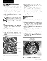
2. Remove the oil drain line from the bottom of the
shaft seal cover plate. (See Fig. 20)
3. Remove the (8) cap screws holding the cover plate
and remove the cover plate. The stationary carbon
seal will remain in the cover plate as it is removed.
Do not touch the carbon seal surface.
4. Remove the snap ring and sleeve.
5. Remove the seal cartridge assembly from the cover
plate. Do not disassemble the cartridge assembly.
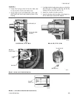
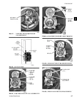
6. Using items from the tool kit as shown in Fig. 21
remove the seal collar from the shaft. (also see Figs.
22 and 23)
COUPLING GUARD
26296A
FIG. 18 –
COUPLING GUARD (OPEN-DRIVE MODELS)
CARBON SEAL
CARTRIDGE
ASSEMBLY
(STATIONARY)
FIG. 19 –
CARTRIDGE TYPE SHAFT SEAL CROSS
SECTION
26439A
SLEEVE
SNAP
RING
COVER
PLATE
DRAIN TUBE
“O” RING
SEAL
COLLAR
“O” RING
Compressor Service
Содержание HA-57
Страница 2: ...YORK INTERNATIONAL 2 ...
Страница 43: ...FORM 160 49 M1 43 YORK INTERNATIONAL NOTES 3 ...


