Yolin YL70E Скачать руководство пользователя страница 7

5

6.2 Setting of number of steel magnets for speed measurement

P2 represents the setting option of number of steel magnets for speed measurement. The adjustable range of the

number is: 1~64. In the parameter modification interface, press the button

to select a parameter, and press and hold the

button

to confirm and save the parameter. When "---" is displayed, it will automatically return to the custom setting

interface.

Fig. 6-2 Setting Interface of Number of Steel Magnets for Speed Measurement

A3 version custom setting:
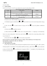
6.3 Rated voltage setting

P1 represents the rated voltage setting option. There are two options for the rated voltage: 36 means the rated voltage is

36V and 48 means the rated voltage is 48V. In the parameter modification interface, press the button

to select a

parameter, and press and hold the button

to confirm and save the parameter. When "---" is displayed, it will

automatically return to the custom setting interface.

Fig. 6-3 Rated Voltage Setting Interface

6.4 Wheel diameter setting

P2 represents the wheel diameter setting option. The adjustable range is 8~28 inches. Select the corresponding wheel

diameter of your e-bike to ensure the accuracy of the speed and distance indication. In the parameter modification interface,

press the button

to select a parameter, and press and hold the button

to confirm and save the parameter. When

"---" is displayed, it will automatically return to the custom setting interface.

Fig. 6-4 Wheel Diameter Setting Interface

Содержание YL70E

Страница 1: ...Tianjin Yolin Technology Co Ltd User Manual for E bike Display YL70E...

Страница 2: ...ssist level selection 3 5 5 Battery level indicator 3 5 6 Error code indicator 3 6 Custom setting 4 6 1 Metric imperial system setting 4 6 2 Setting of number of steel magnets for speed measurement 5...

Страница 3: ...ng current 18mA Maximum working current 30mA Leakage current at power off 1uA Working current at the supply controller end 50mA Working temperature 20 60 Storage temperature 30 70 3 Appearance and dim...

Страница 4: ...supply of the controller will be turned on In the power on state by pressing and holding the button your e bike will be powered off In the power off state the display will no longer use the battery po...

Страница 5: ...s 1 9 Fig 5 3 Assist Level Switching Interface 5 5 Battery level indicator The battery level indicator consists of four segments When the battery is fully charged the four segments will be all on In c...

Страница 6: ...ameter selection 4 Press and hold the button to confirm and save the parameter When is displayed it will automatically return to the custom setting interface Alternatively press the button to return t...

Страница 7: ...ge 36 means the rated voltage is 36V and 48 means the rated voltage is 48V In the parameter modification interface press the button to select a parameter and press and hold the button to confirm and s...

Страница 8: ...y will be responsible for providing limited warranty during the warranty period The warranty period of the product is within 12 months from delivery 7 2 Non warranty scope The enclosure is opened The...

Страница 9: ...es of the Company part of the displayed contents or functions of the product you bought may be different from the manual depending on the actual model Schedule 1 Error Code Definitions Error codes for...

Отзывы: