


3-1
IM WT18O1E-02EN
3.1 Setting Motor Evaluation Conditions
This section explains the following settings for motor evaluation conditions. This feature is available on
models with the /MTR option.
• Scaling factor
• Unit
• Input signal type
• Analog input range
• Analog input linear scale
• Line filter
• Synchronization source
• Pulse input range
• Torque signal pulse rating
• Number of pulses per revolution of the revolution signal
• Motor’s number of poles for computing the synchronous speed
• Voltage or current whose frequency is measured to compute the synchronous speed
• Electrical angle measurement
• Motor efficiency and total efficiency computations
►
“Motor Evaluation Conditions (Option)” in the features guide
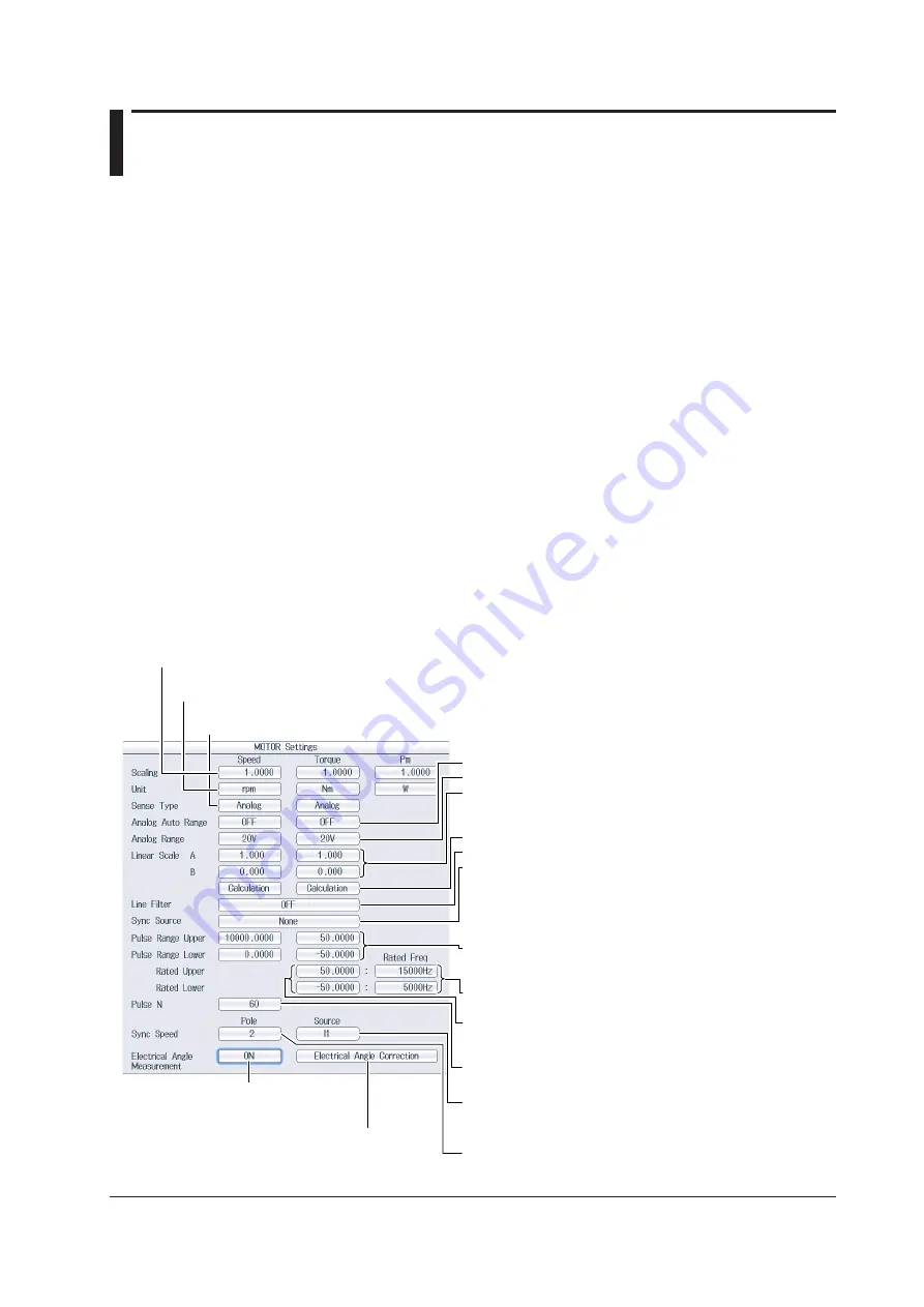
Setting Motor Evaluation Conditions (MOTOR Settings)
Press
SHIFT+SCALING
(MOTOR/AUX SET) to display the following screen.
On models with the /AUX option, the auxiliary input conditions setup screen is displayed. See section 4.1.
When Sense Type is set to Analog:
• Turns the auto range on and off
• Set the fixed range (20V, 10V, 5V, 2V, 1V).
• Set the linear scale (A: 1.000 m to 1.000 M; B: −1.000 M to
1.000M).
Set A (the slope) and B (the offset).
• Computes A and B
• Set the line filter (OFF, 100Hz, 1kHz).
• Set the synchronization source (U1, I1, U2, I2, U3, I3, U4, I4,
U5, I5, U6, I6, Ext Clk, None).
Even if Sense Type is set to Pulse, correctly setting the
synchronization source improves measurement accuracy.
When Sense Type is set to Pulse:
• Set the upper and lower limits.
Revolution signal: 0.0000 to 99999.9999 [rpm]
Torque signal: −10000.0000 to 10000.0000 [N•m]
• Set the positive and negative rated torque signal pulse
frequencies (1 to 100000000 [Hz]).
• Set the positive and negative rated torque signal values
(−10000.0000 to 10000.0000 [N•m]).
Set the number of pulses per revolution of the revolution
signal (1 to 9999).
Set the voltage or current whose frequency will be measured
to compute the synchronous speed (U1, I1, U2, I2, U3, I3, U4,
I4, U5, I5, U6, I6).
Set the number of motor poles that will be used to compute
the synchronous speed (1 to 99).
Set the scaling factor (0.0001 to 99999.9999).
Set the scaling factor that is used to convert the signal from the revolution sensor or torque meter to
speed (rotating speed), torque, and Pm (motor output).
Set the unit (up to 8 characters).
Set the speed, torque, and Pm units.
Set the input signal type (Analog, Pulse).
Set the type of revolution sensor for Speed and the type of the torque meter for Torque.
Turns electrical angle
measurement on and off
Configure the electrical angle correction.
You can configure the electrical angle correction
when Electrical Angle Measurement is set to ON.
Chapter 3
Motor Evaluation Conditions (Option)