8
IM 04L55B01-02EN
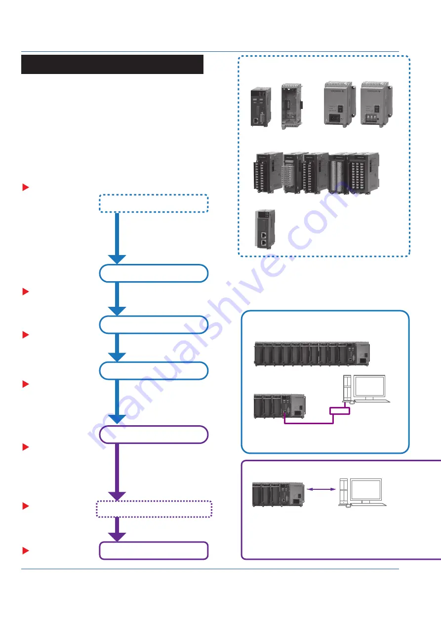
Operating Procedure
I/O modules
1
(without the terminal covers)
Configure functions as necessary.
Turn on the power.
Prepare modules.
Check the modules.
Install the module base.
Link the modules.
Installation
Installing the Module Base
Checking the Modules
Linking the Module Base (Module)
Set the date and time.
Set signal inputs.
Reconfigure.
Set the measurement mode
Set the GM10 IP address.
Configure the GM settings.
Connect I/O signals and power.
Configure the system.
System Configuration
Multi Unit System
GX90EX linking position
Single Unit System
Configuration
Ethernet
USB
Bluetooth(/C8)
Main unit
Sub unit
Hub
Main unit
Sub unit
Sub unit
Sub unit
Indicates a reference.
“Wiring”
“Wiring”
“Basic Operations”
“Basic Operations”
Start recording/measuring.
URL: www.smartdacplus.com/manual/ja/
URL: www.smartdacplus.com/software/ja/
User’s Manual
(IM 04L55B01-01EN)
“Operating Procedure”
“Installation”
GM10
GX90EX
2
GX90EX
GM90MB
GM90PS
GM90MB
GM90MB
Module
Latch
GX90EX
Slide locks (vertical)
Lock
Unlock
Slide locks (vertical)
Screw (M3)
Connector
M3 screws for linking (included)
(top and bottom; 4)
Insert the module from the front of the GM90MB
until a click is heard. Then, fasten the screw.
(Recommended tightening torque: 0.6 N•m)
GM supports both standalone operation and data acquisition
using a PC.
Use a PC to configure the GM settings. To download the
dedicated software application, you need to connect to the
Internet.
If you need to set the time
zone or DST (Daylight Saving
Time) or both, do so before
setting the date and time.
Download the following software applications.
S Standard Hardware Configurator
S Standard IP Address Configurator
See the list of electronic manuals on page 4 of IM 04L51B01-91EN,
and download them if necessary.
Hardware Configurator is required for USB communication or
Bluetooth communication (/C8 option).
A dedicated software application is not required for Ethernet
connections.
(IP Address Configurator is used during installation.)
• Search for GM10s in the same network segment and list them.
• Set the IP address and other parameters of the GM10.
• GM settings can be configured offline from a Web browser.
IP Address Configurator Screen Example
Hardware Configurator Screen Example
Configuration of settings and real time monitoring
are possible using a Web application.
A PC with Internet Explorer installed is required.
A system configured with a main unit connected to sub units.
Up to six sub units can be connected to a main unit. Each
unit can connect up to six modules.
* There is a limitation on the number of channels based on
the GM10 specifications (see IM 04L55B01-01EN).
A system configured with only a main unit.
The multi unit system support only cascaded connections.
If connected in a ring, none of the sub units will be identified.
Link the GX90EX to the left
end on a main unit and next to
the GM90PS on a sub unit.
Do not connect to avoid a
ring connection.
For wall mounting, mount the GM90MB to
the wall first, and then install the modules.
Protrusion
(top and bottom; 4)
Guides (top and
bottom; 4)
1. Check that the slide lock (vertical) is released (see below), align the four
protrusions of the GM90MB to the guide, and push it in.
Removing a Module
1. Loosen the screw at the bottom section of the module.
2. While pressing down on the latch at the top of the module,
pull the module out.
1 Some of the modules that can be used with the GM
have firmware version conditions. See page 6.
2 The GX90EX is used to configure a multi unit
system.
The firmware version of the GX90EX that can be
used with the GM must be R1.02.01 or later.
2. After linking the module base, fix in place using the slide lock or the supplied screw.
(Recommended tightening torque: 0.4 to 0.5 N•m)
Push in
When carrying the unit, be sure that the
modules are securely installed.
Lock: Slide toward the back of the module.
Unlock: Slide toward the front of the module.
You will hear a click both when
locking and when unlocking.
Product user’s manuals can be downloaded from the following URL.
You can download the latest version of the software from the
following URL.
Power supply connection:
Inlet or M4 screw terminal
PC
PC
Operations on the GM
Operations on the PC
Maximum connection distance
between two units is 100 m.
Maximum connection distance
between two units is 100 m.
A document number is
indicated for manuals
other than this manual.


