2-16
IM 701240-01E
The accuracy improves when
the smoothing filter is used.
Original waveform
When using the smoothing filter
Filter order: 50 ms
• When using the offset function (see this page) and making
measurements by expanding near 100 kHz
•Value/div:
200 Hz/div
•Upper display limit: 101 kHz
•Lower display limit: 99 kHz
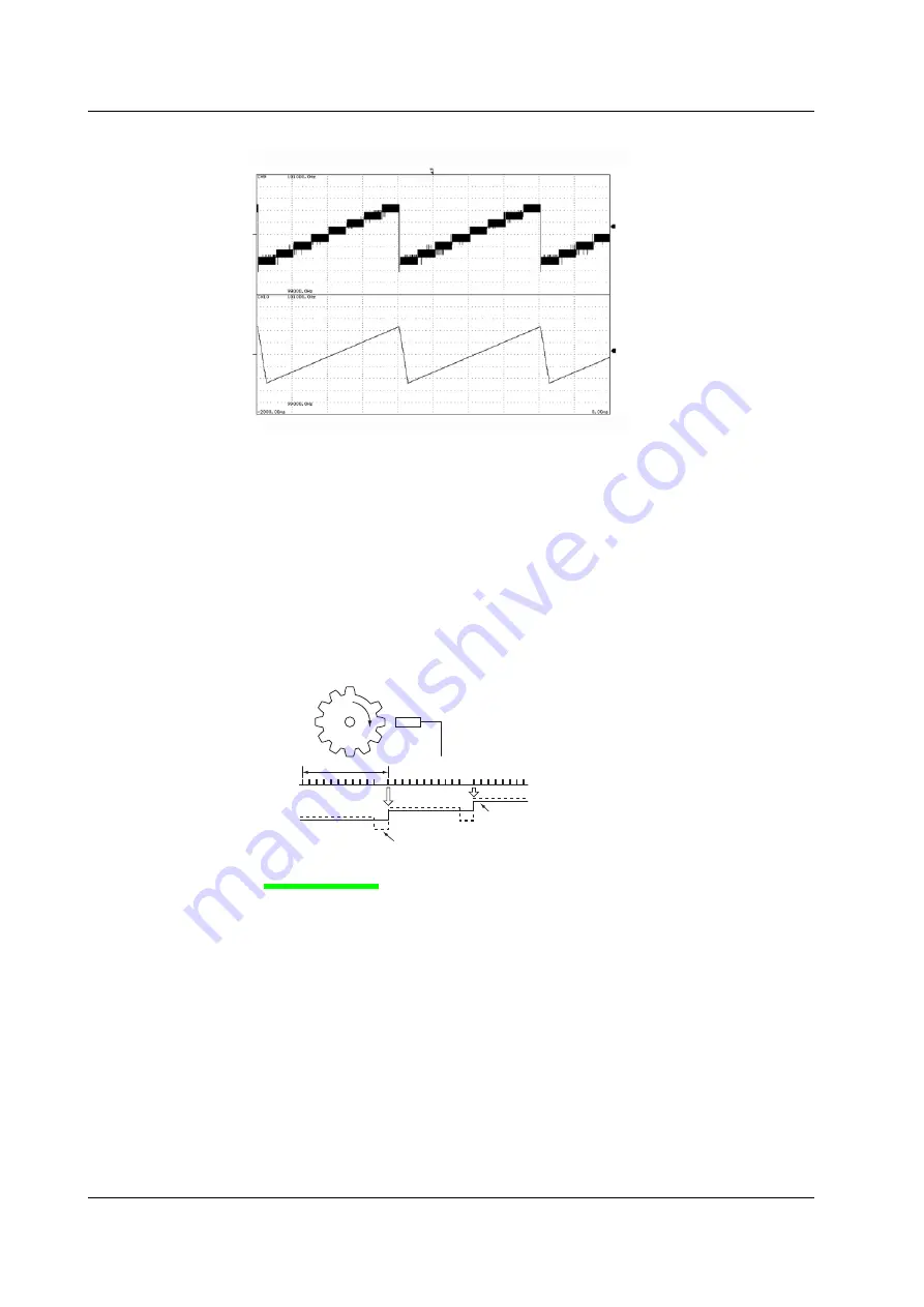
Pulse Average
Measures the input pulse by dividing the pulse by the specified number of pulses (1 to
4096 pulses). The pulse average has the following characteristics.
• If pulse dropouts are present or pulse interval is fluctuating within a period,
measurements can be made by eliminating the effects from the dropout or
fluctuation (fluctuating component of the waveform used to measure the frequency
or period).
• The measured result is displayed as a value per input pulse even when pulse
average is used. Therefore, there is no need to perform scaling again.
• Can be used when measuring frequency, number of rotations, power supply
frequency, pulse integration, and velocity.
f
1
f
2
f
3
N = 11
When pulse average is used
When pulse average is not used
Offset Function
The 701280 (FREQ) allows you to set the center of observation (offset value) and
expand the area around the offset value for close observation. It allows you to measure
the fluctuation around a certain frequency.
Logic Waveforms «For procedures, see section 5.18.»
Logic waveforms can be measured by connecting logic probes to the logic signal input
connectors (two connectors marked Logic A and Logic B) on the left side panel. A-1 to A-
8 (8 bits) and B-1 to B8 (8 bits) can be applied to the Logic A and Logic B ports,
respectively.
2.2 Setting the Horizontal and Vertical Axes


