background image

12-4

IM 701240-01E

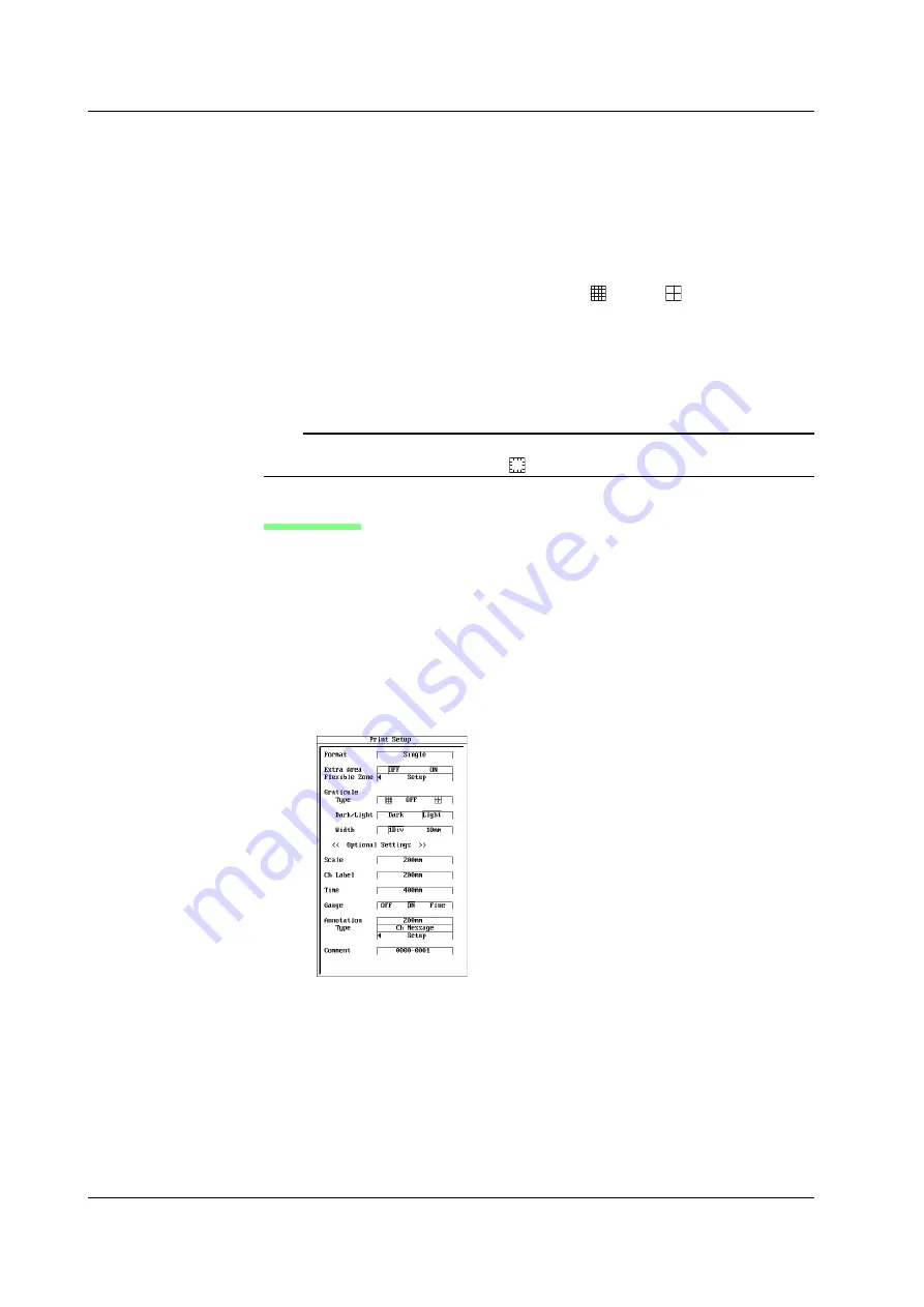
Setting the Flexible Zone

(Can be set when you select 1 Zone in step 12 on page 12-3)

14.

Use 

jog shuttle

+

SELECT

 to select Setup in Flexible Zone.

15.

Use 

jog shuttle

+

SELECT

 to set Mode to OFF or ON.

16.

Use 

jog shuttle

+

SELECT

 to set Upper/Lower of the waveform to be recorded.

Setting the Graticule

• Setting the Grid

17.

Use 

jog shuttle

+

SELECT

 to set the type to 

, OFF, or 

.

• Setting Dark/Light

18.

Use 

jog shuttle

+

SELECT

 to set dark/light to light or dark.

• Setting the Width of the Vertical Scale

19.

Use 

jog shuttle

+

SELECT

 to set the width to 1div or 10mm.

Proceed to step 19.

Note

The grid setting is linked with the DISPLAY menu > Graticule setting. However, if OFF is
selected, the DISPLAY menu is set to 

.

Setting Details

Setting the Print Interval of Scale Values

20.

Use 

jog shuttle

+

SELECT

 to set the scale to OFF, 200mm, 400mm, or 800mm.

Setting the Print Interval of Channel Labels

21.

Use 

jog shuttle

+

SELECT

 to set Ch Label to OFF, 200mm, 400mm, or 800mm.

Setting Whether to Print the Time

23.

Use 

jog shuttle

+

SELECT

 to set the time to OFF, 200mm, 400mm, or 800mm.

Setting the Gauge Print

23.

Use 

jog shuttle

+

SELECT

 to set the gauge to OFF, ON, or Fine.

12.1  Printing on the Built-in Printer

Содержание SL1400 ScopeCorder LITE

Страница 1: ...ScopeCorder LITE IM 701240 01E 4th Edition SL1400 ...

Страница 2: ...asing YOKOGAWA products YOKOGAWA provides registered users with a variety of information and services Please allow us to serve you best by completing the product registration form accessible from our homepage http tmi yokogawa com PIM 103 03E ...

Страница 3: ...paration of this manual to ensure the accuracy of its contents However should you have any questions or find any errors please contact your nearest YOKOGAWA dealer Copying or reproducing all or any part of the contents of this manual without the permission of YOKOGAWA is strictly prohibited The TCP IP software of this product and the document concerning the TCP IP software have been developed crea...

Страница 4: ...ii IM 701240 01E Revisions 1st Edition June 2006 2nd Edition October 2006 3rd Edition May 2009 4th Edition September 2013 ...

Страница 5: ... the EU contact your local Yokogawa Europe B V office New EU Battery Directive New EU Battery Directive DIRECTIVE 2006 66 EC This directive is valid only in the EU Batteries are included in this product This marking indicates they shall be sorted out and collected as ordained in ANNEX II in DIRECTIVE 2006 66 EC Battery type 1 Lithium battery You cannot replace batteries by yourself When you need t...

Страница 6: ...e instrument See the next page for information on the input module Power cord1 D UL CSA Standard power cord Part No A1006WD Maximum rated voltage 125 V F VDE Standard power cord Part No A1009WD Maximum rated voltage 250 V Q BS Standard power cord Part No A1054WD Maximum rated voltage 250 V R AS Standard power cord Part No A1024WD Maximum rated voltage 250 V H GB Standard power cord Part No A1064WD...

Страница 7: ... on the input module is what you ordered MODEL Name Abbreviation 701250 High Speed 10 MS s 12 Bit Isolation Module HS10M12 701251 High Speed High Resolution 1 MS s 16 Bit Isolation Module HS1M16 701255 High Speed 10 MS s 12 Bit Non Isolation Module NONISO_10M12 701267 High Voltage 100 kS s 16 Bit Isolation Module with RMS HV with RMS 701261 Universal Voltage Temp Module UNIVERSAL 701262 Universal ...

Страница 8: ...Vrms CAT II 2 pieces in one set red black for 4 mm screws Cables3 366926 For measuring low voltage of less than or equal to 42 V Banana alligator clip cable 366961 For measuring low voltage of less than or equal to 42 V for the 701261 701262 or 701265 High speed logic probe 700986 42 V or less 8 bit non isolated response speed of 1 µs Isolated logic probe 700987 250 Vrms CAT II 8 bits each channel...

Страница 9: ...t lead 758933 must be used with one of the following accessories which are sold separately alligator clip dolphin type 701954 safety mini clip hook type 701959 alligator adapter 758922 or 758929 and or the fork terminal adapter 758921 Soft carrying case 701967 High speed logic probe 700986 Isolated logic probe 700987 Measurement lead for isolated logic 758917 Alligator clip adapter Rated voltage 3...

Страница 10: ...ility for the customer s failure to comply with these requirements The following symbols are used on this instrument Warning handle with care Refer to the user s manual or service manual This symbol appears on dangerous locations on the instrument which require special instructions for proper handling or use The same symbol appears in the corresponding place in the manual to identify those instruc...

Страница 11: ...e to connect the protective earth to prevent electric shock before turning ON the power The power cord that comes with the instrument is a three prong type power cord Connect the power cord to a properly grounded three prong outlet Do Not Impair the Protective Grounding Never cut off the internal or external protective earth wire or disconnect the wiring of the protective earth terminal Doing so p...

Страница 12: ...e 42 V be sure to use the passive probe 701940 The BNC part of the passive probe 701940 is made of metal Therefore use the probe at 42 V or less for isolated inputs 701250 HS10M12 701251 HS1M16 etc for safety reasons Do not connect voltage above 42 V to both the High and Low sides For non isolated inputs 701255 NONISO_10M12 etc fasten the module screws as described before When measuring high volta...

Страница 13: ...on of the instrument Notations Used in the Procedural Explanations On pages that describe the operating procedure in Chapters 3 through 17 the following notations are used to distinguish the procedure from their explanations Procedure Follow the numbered steps All procedures are written with inexperienced users in mind experienced users may not need to carry out all the steps Explanation This sect...

Страница 14: ...surement Etc 3 3 Number of rotations period duty cycle power supply frequency pulse width pulse integration and velocity Number of rotations period duty cycle power supply frequency pulse width pulse integration and velocity Voltage Measurement Temp Measurement Strain Measurement Acceleration Measurement Frequency Measurement Etc 2 Only when measuring voltage with the 701261 701262 701267 or 70126...

Страница 15: ...ction 9 7 Create a PDF file of the reprint image Section 9 8 Setting the Trigger Setting the Trigger Trigger type simple enhanced Sections 6 5 to 6 17 Trigger source trigger slope trigger level etc Sections 6 5 to 6 17 Trigger mode Sections 6 1 and 7 4 Trigger position Section 6 2 Trigger delay Section 6 3 From the previous page Simple trigger Input signal trigger Sections 6 5 and 6 9 External tri...

Страница 16: ...int on a USB Printer Section 12 2 Printing on a Network Printer Sections 15 4 and 12 3 Computing Analyzing and Searching Waveforms Computing Analyzing and Searching Waveforms Waveform computation Sections 10 1 to 10 4 History search Sections 11 2 and 11 3 Cursor measurement Section 11 4 Automated measurement of waveform parameters Section 11 5 Statistical processing Section 11 6 From Acquiring Wav...

Страница 17: ... 15 7 Use the SL1400 as a Windows network drive Section 15 11 Personal computer PC or workstation Other Operations Set the menu message language Section 16 1 Turn the click sound ON OFF Section 16 1 Change the screen font size Section 16 2 Set the screen color and intensity Section 16 3 Set the backlight Section 16 4 Lock the keys Section 16 5 Ethernet interface and other operations do not have to...

Страница 18: ... Measurements 3 1 Handling Precautions 3 1 3 2 Installing the Instrument 3 3 3 3 Installing Input Modules 3 5 3 4 Connecting the Power Supply and Turning the Power Switch ON OFF 3 8 3 5 Loading the Roll Paper for the Built in Printer 3 10 3 6 Setting the Date and Time 3 13 3 7 Connecting Probes 3 15 3 8 Compensating the Probe Phase Correction 3 21 3 9 Connecting Measurement Leads 3 23 3 10 Connect...

Страница 19: ...etting the Record Time and Sample Rate 5 2 5 5 Selecting the Input Coupling 5 8 5 7 Selecting the Bandwidth Limit 5 11 5 14 Setting the Temperature Measurement 5 23 5 19 Entering Settings on the All Channel Menu 5 46 5 20 Selecting the Time Base Internal Clock or External Clock 5 49 Strain Measurement Input Module 701270 or 701271 5 1 Turning Channels ON OFF 5 1 5 2 Setting the Record Time and Sam...

Страница 20: ...e Trigger Mode 6 1 6 2 Setting the Trigger Position 6 3 6 3 Setting the Trigger Delay 6 5 6 4 Setting the Hold Off Time 6 6 6 5 Setting the Edge Trigger SIMPLE 6 8 6 6 Setting the External Trigger SIMPLE 6 11 6 7 Activating Triggers on the Power Signal SIMPLE 6 12 6 8 Setting the Timer Trigger SIMPLE 6 13 6 9 Setting the Logic Trigger SIMPLE 6 15 6 10 Setting the A B N Trigger ENHANCED 6 17 6 11 S...

Страница 21: ...ting the Record Conditions of T Y Waveform Recording 9 3 9 3 Setting the Recording Format of T Y Waveform Recording 9 6 9 4 Recording T Y Waveforms 9 11 9 5 Recording Numeric Values 9 13 9 6 Recording X Y Waveforms 9 16 9 7 Reprinting on the Built in Printer 9 20 9 8 Creating a PDF File of the Reprint Image 9 24 Chapter 10 Waveform Computation 10 1 Adding Subtracting Multiplying and Dividing Wavef...

Страница 22: ...ger I O External Clock Input and Video Signal Output 14 1 External Trigger Input TRIG IN 14 1 14 2 Trigger Output TRIG OUT 14 2 14 3 External Clock Input EXT CLK IN 14 3 14 4 Video Signal Output VIDEO OUT SVGA 14 4 14 5 External Start Stop Input 14 6 Chapter 15 Ethernet Interface Option 15 1 Connecting the SL1400 to the Network 15 1 15 2 Setting up the TCP IP 15 3 15 3 Saving Loading Data to a Net...

Страница 23: ...me Sample Rate and Record Length in Memory Mode App 1 Appendix 2 Relationship between the Chart Speed Sample Rate and Record Length in Recorder Mode App 2 Appendix 3 Maximum Number of Acquisitions to the History Memory and Time Axis Range That Allows Realtime Recording App 3 Appendix 4 How to Calculate the Area of a Waveform App 4 Appendix 5 ASCII Header File Format App 6 Appendix 6 List of Defaul...

Страница 24: ...on of the displayed information see chapter 8 Used to select items on the soft key menu that appears when setting up the SL1400 Panel keys knobs Used to clear the soft key menu and pop up menu For a description see section 1 2 For a description see section 1 2 Panel keys Probe compensation signal output terminal 1 kHz 1 VP P Functional ground terminal Connect the ground cable when be sure to perfo...

Страница 25: ...ots in the top and bottom rows For the installation and removal procedure of input modules see section 3 3 Empty slot protection cover panel Attached to the slots that are not used For the installation procedure see section 3 2 CH1 ON OFF PROBE POWER 12V CH2 CH3 CH4 CH5 CH6 CH7 CH8 CH9 CH10 CH11 CH12 CH13 CH14 CH15 CH16 Input module connector Acquisition memory backup ON OFF Turns ON OFF the batte...

Страница 26: ...h Universal Voltage Temp Module with AAF UNIVERSAL AAF model 701262 H input terminal L input terminal 2ch High Speed 10 MS s 12 Bit Non Isolation Module NONISO_10M12 model 701255 High Voltage 100 kS s 16 Bit Isolation Module with RMS HV with RMS model 701267 Input terminal 2ch Strain Module NDIS STRAIN_NDIS model 701270 Strain Module DSUB Shunt Cal STRAIN_DSUB model 701271 Input terminal 2ch Input...

Страница 27: ...rminal see section 13 5 USB connector for a personal computer PC Used to connect a PC with a USB interface For a description on how to use the terminal see the Communication Interface User s Manual External start stop input connector Used to externally control the start stop of the SL1400 For a description on how to use the terminal see section 14 5 USB connector for peripherals Used to connect a ...

Страница 28: ...rn the display of each channel ON OFF section 5 1 set the vertical position section 5 4 coupling section 5 5 Probe attenuation or current to voltage conversion ratio section 5 6 bandwidth limit section 5 7 vertical axis expansion reduction sections 5 8 and 5 9 linear scaling section 5 11 inverted display of waveforms section 5 12 and waveform label section 8 10 If you select Logic A or Logic B a m...

Страница 29: ...T menu that appears when you press the MENU key IMAGE SAVE Key Section 13 12 Saves the screen image data to a storage medium You can enter the storage settings of the screen image data on the IMAGE menu that appears when you press the MENU key SNAPSHOT Key Section 8 7 Leaves the current displayed waveform on the screen in black and white Waveforms acquired using the snapshot function can be saved ...

Страница 30: ...Vertical position section 5 4 Time from the trigger position section 6 2 Trigger type chapter 6 Soft key menu Level indicator section 8 12 Channel number of the displayed waveform Record length see the explanation below See the explanation below Time per division Record time Span corresponding to the displayed waveform section 5 3 Date time when the displayed waveform was acquired Current date tim...

Страница 31: ...n the normal waveform Zoom range of Z1 Display position of zoom waveform Z1 on the normal waveform T div time per division of Z2 Normal waveform display area Zoom waveform display area T div time per division of Z1 Z1 zoom waveform display area Z2 zoom waveform display area Record length of Z1 Record length of Z2 Zoom range of Z2 1 3 Display Screens ...

Страница 32: ...through command communications SCSI data download SL1400 1 High Speed 10 MS s 12 Bit Isolation Module High Speed High Resolution 1 MS s 16 Bit Isolation Module High Speed 10 MS s 12 Bit Non Isolation Module High Voltage 100 kS s 16 Bit Isolation Module with RMS Temperature High Precision Voltage Isolation Module Universal Voltage Temp Module Universal Voltage Temp Module with AAF Strain Module NDI...

Страница 33: ...put module Here the high speed 10 MS s 12 bit isolation module 701250 HS10M12 is used as an example for the explanation For details on the flow of the signal of each module see the block diagram The signal applied to the two input terminals is first processed by the input section of each module On the 701250 HS10M12 1 the attenuator ATT attenuates and the amplifier AMP amplifies the input signal 2...

Страница 34: ...put through the external clock input terminal on the left panel facing the SL1400 This external clock input is useful for observing a signal whose period varies or for observing waveforms by synchronizing to the clock signal of the signal being measured T div T div is 1 10th the record time or the time per one grid square 1 div 1 div 500 µs 10 div 1 div 1 ms Record time 5 ms 10 div Record time 10 ...

Страница 35: ...owever if the record length is greater than or equal to 2 kW the maxim and minimum values are determined P P compression and aligned at the same time position total number of points 2002 to draw the waveform 1001 points 0 1000 Sampled data Time axis Record length Record length P P compression display Maximum value Minimum value 1001 points is a logical number of points On the screen the data is co...

Страница 36: ...s 100100 only the data per given interval is displayed In other words the data is decimated down to 100100 points 100 k points for displaying the waveform Record Time and Roll Mode Display If the trigger mode is set to Auto Auto Level Single or Log and the record time is set greater than or equal to 1 s div the waveform is displayed in roll mode In roll mode the displayed waveform is not updated u...

Страница 37: ...he following functions can be used to move the displayed waveform and display the waveform outside the display range by expanding reducing the displayed waveform Move the vertical position See page 2 7 Zoom in or out vertically expand reduce See page 2 7 2400 levels 5 div 5 div 10 div 0 V 10 div Measurement range 20 div Displayed range 10 div Note For measuring the voltage with high accuracy To me...

Страница 38: ... Zooming in or out Vertically For procedures see sections 5 8 and 5 9 Zooming in or out by Setting the Magnification You can expand or reduce the waveform display vertically in the range of 0 1 to 100 varies depending on the input module for each displayed waveform The waveform display can be zoomed around the vertical position 1 div 0 5 V If V Zoom is set to 2 1 div 1 V Vertical position mark Gro...

Страница 39: ...to the attenuator of the vertical control circuit By selecting GND you can check the ground level on the screen Vertical control circuit Input terminal 1 MΩ Vertical control circuit Input terminal 1 MΩ Vertical control circuit Input terminal DC AC GND TC Only When Measuring the Temperature Select TC if you are measuring the temperature using the 701261 UNIVERSAL 701262 UNIVERSAL AAF or 701265 TEMP...

Страница 40: ...acity of each module Otherwise the capacity cannot be adjusted Bandwidth Limit For procedures see section 5 7 A bandwidth limit can be applied for each module By limiting the bandwidth you can eliminate high frequency components such as high frequency noise from the input signal for waveform observation Linear Scaling For procedures see section 5 11 When measuring the voltage current strain or fre...

Страница 41: ...will correspond to one mechanical rotation one cycle The selectable range is from 1 to 24000 pulses For example if the pulse rotate setting is set to 100 pulses then 10 rotations of data samples will be acquired when the record length is set to 1 kW When the pulse rotate setting is set to 1 pulse one data sample will correspond to one rotation one cycle The pulse rotate setting affects only the X ...

Страница 42: ... velocity 2 πf where f is the frequency of the sinusoid signal the rms value Vrms is derived from Vrms The average of u t 2 over one cycle 1 2π 0 Vmsinwt 2 dwt Vm 2 2π As in the above example when Vm is 2 V the rms value Vrms is approximately 1 4 V DC RMS This setting is used when you want to observe the rms values of both the DC and AC components of the input signal Example When the rms value of ...

Страница 43: ...ed by connecting a strain gauge bridge bridge head or a strain gauge transducer to the strain module 701270 STRAIN_NDIS or 701271 STRAIN_DSUB Relationship between the Strain µSTR and the Transducer Output mV V The SL1400 allows the unit to be changed between the strain unit µSTR 10 6 strain and the output unit of the strain gauge transducer mV V The following relationship exists between µSTR and m...

Страница 44: ...fier Current Supply to Acceleration Sensors The 701275 ACCL VOLT can supply 4 mA of current to the acceleration sensor when measuring acceleration Filter If you set the bandwidth limit to Auto the anti aliasing filter AAF and low pass filter are enabled depending on the sample rate to eliminate high frequency noise from the input signal Using the anti aliasing filter when measuring voltage allows ...

Страница 45: ...nce Flow Rate Pulse integrated value N count physical amount per pulse I Set the physical amount per pulse I to distance or flow rate A suitable user defined unit can be assigned to the specified physical amount N count l Velocity Velocity km h Distance per pulse l km Tw s 3600 Velocity m s Distance per pulse l m Tw s The distance and unit can be user defined angular velocity etc Tw s Distance per...

Страница 46: ...nd the frequency is set to 0 The time from the point when the pulse input stops to the point when the function determines that the object has stopped can be set to 1 5 2 3 9 and 10 10 settings of the pulse period T of the pulse one period before the pulse input stopped f0 T T n n 1 5 to 10 f 1 t t Deceleration prediction Pulse input stop Stop prediction 0 Filter Smoothing Filter Moving Average The...

Страница 47: ...r period The measured result is displayed as a value per input pulse even when pulse average is used Therefore there is no need to perform scaling again Can be used when measuring frequency number of rotations power supply frequency pulse integration and velocity f1 f2 f3 N 11 When pulse average is used When pulse average is not used Offset Function The 701280 FREQ allows you to set the center of ...

Страница 48: ... when the specified trigger condition is met At this point the waveform is ready to be displayed on the screen Trigger slope refers to the rising or falling edge of the signal Trigger level When set to rising the trigger occurs here Trigger source External Trigger A trigger is activated using the external signal applied to the EXT TRIG IN terminal on the side panel of the SL1400 Line Trigger A tri...

Страница 49: ...Disable Do not use logic input Enable Use logic input CH1 to CH16 L Low level H High level X Don t care A Delay B Trigger A trigger is activated the first time condition B becomes true after condition A has become true and a preset time has elapsed Condition A Condition B Condition Enter True when the preset condition is met Exit True when the preset condition is not met LogicA LogicB Disable Do n...

Страница 50: ... in the preset pattern False While all channels do not match the preset pattern LogicA LogicB Disable Do not use logic input Enable Use logic input Rising Falling Don t care CH1 to CH16 L Low level H High level X Don t care OR Trigger A trigger is activated when any of the channels set to edge trigger meets the condition For example a trigger can be activated on the rising edge of CH1 or CH2 Logic...

Страница 51: ...tion B is met exceeds or drops below a preset time In the case of a timeout trigger a trigger is activated when a preset time elapses LogicA LogicB Disable Do not use logic input Enable Use logic input CH1 to CH16 L Low level H High level X Don t care B Time Trigger B Trigger Time B Pulse width B Time Trigger B Trigger Time B TimeOut Trigger B Trigger Time 2 3 Setting the Trigger ...

Страница 52: ... µs B is true CH1 8 µs 8 µs B is true B is true 12 µs B is true Trigger activated here T Time A trigger is activated when condition B is met the second time if the time T when condition B is met the second time is shorter than a specified time When condition B CH1 H and Time 10 µs B is true CH1 B is true B is true B is true Trigger activated here 12 µs 12 µs 8 µs T1 T T2 A trigger is activated whe...

Страница 53: ...ue 4 µs B is true Trigger activated here Window Trigger A certain voltage range window is set and a trigger is activated when the trigger source level enters this voltage range IN or exits from this voltage range OUT Width Trigger is activated OUT Trigger is activated IN Window Window Trigger is activated Center Width Center IN Enters the window OUT Exits from the window Don t care CH1 to CH16 Don...

Страница 54: ...en the current waveform falls outside the realtime template Trigger activated here Wave Window Trigger Example Disruption Trigger Sag Trigger Sag Trigger Surge Trigger ON Use as a trigger source OFF Not use as a trigger source CH1 to CH16 Cycle Frequency Power supply frequency of the measured item Reference Cycle Sync Ch Synchronization channel1 for starting triggers Level Level of the synchroniza...

Страница 55: ...e amplitude Trigger level Amplitude Normal Mode The waveform display is updated only when a trigger occurs The displayed waveforms are not updated if a trigger does not occur Single Mode When a trigger is activated the displayed waveforms are updated only once and acquisition stops This mode is suitable for observing a single shot signal Single N Mode Sequential Store Function This mode is selecte...

Страница 56: ...int and the trigger position match By moving the trigger position you can observe the pre trigger section of the waveform before the trigger point Display record length Trigger position Pre trigger section Post trigger section 0 100 Trigger Source Trigger Slope and Trigger Level For procedures see sections 6 5 to 6 16 Trigger Source Trigger source refers to the target channel on which trigger cond...

Страница 57: ...ou want to display the waveform in sync with repetitive cycles or when using the history memory function described later and you want to change the waveform acquisition period Input signal Repetition period T Trigger level Trigger source signal t Trigger signal limited by hold off time t when the trigger slope is set to rising edge Action on Trigger For procedures see section 6 18 A specified acti...

Страница 58: ...13 14 15 16 17 18 App Index Explanation of Functions Manual Trigger For procedures see section 6 19 You can activate a trigger regardless of the specified trigger condition by pressing the MANUAL TRIG key on the front panel 2 3 Setting the Trigger ...

Страница 59: ...nential average when set to infinite AN N Simple average when set to 2 to 65536 N n 1 Σ Xn An Xn N nth averaged value nth measured value Attenuation 2 to 256 2n steps Xn N nth measured value Average count acquisition count 2n steps Averaging is effective such as when eliminating the random noise riding on the signal Envelope Mode In normal mode and averaging mode if you increase the record time yo...

Страница 60: ... block is updated in order until the measurement is stopped However in the sequential store function you specify the waveform acquisition count number of blocks and the measurement stops when the specified count is reached The updating of the waveform display is carried out after acquiring the entire waveform data To acquire waveforms using this function set the trigger mode to Single N The maximu...

Страница 61: ...e specified number of waveforms have been stored you can display any of the waveforms individually or all of them together This function is useful when capturing the changes in the waveform over time The following figure indicates an example when N 100 Holds waveform data of the last 100 triggers Selected Record No 0 Selected Record No 25 Currently displayed waveform Selected Record No 0 Displays ...

Страница 62: ...ing with the start of waveform acquisition and stops realtime recording when the specified record time is reached Continue Starts realtime recording with the start of waveform acquisition and stops realtime recording when the specified record time is reached This sequence is repeated the specified number of times count If you select Single Auto or Log trigger modes are available If you select Cont...

Страница 63: ... backed up even when the power supply is cut off The data held in the acquisition memory is backed up immediately before the power is turned OFF This function protects the data in the acquisition memory from sudden power failures Alkaline dry cells or nickel hydride rechargeable batteries four AAA batteries are required for the backup The backup time varies depending on the operating environment F...

Страница 64: ...dots without performing interpolation Linear Interpolation Sine Interpolation Interpolation OFF If the interpolation is OFF waveforms are displayed using dots In this setting up to 100100 points 100 kpoints of the acquired data are displayed without using P P compression page 2 4 For details see page 2 5 Graticule For procedures see section 8 3 You can change the type of graticule that is displaye...

Страница 65: ...locations can be displayed simultaneously dual zoom Below are the combinations of the display methods of zoom waveforms Main Main waveform display frame Z1 Z2 Zoom waveform display frame Main Z1 or Z2 Main Z2 Z1 Z1 Z2 Z1 or Z2 When displaying Main main waveform and Z1 or Z2 zoomed waveform simultaneously a zoom box indicating the zoom position is displayed within the main waveform display frame Th...

Страница 66: ... procedures see section 8 7 If the trigger mode is set to a mode other than single the displayed waveforms are periodically updated or displayed in roll mode The snapshot function allows you to temporarily hold the waveform that would be cleared when the screen is updated snapshot waveform on the screen The snapshot waveform is displayed in white allowing for easy comparison against the updated wa...

Страница 67: ...form Display Area Expansion For procedures see section 8 13 If you clear the setup menu by pressing ESC channel information is displayed such as the voltage division input coupling probe attenuation type bandwidth limit temperature division thermocouple type µSTR division or mV V division measurement range acceleration div gain bias value division measurement mode and preset settings However some ...

Страница 68: ...r division The recording can also be stopped automatically after recording a specified length shot recording Numeric Value Recording Numeric values can be recorded at the specified time interval 1 s to 60 min Up to 16 channels can be recorded If waveform acquisition is started on more than 16 channels 16 channels are recorded in the following order CH1 to CH6 Logic A and Logic B Acquisition Mode d...

Страница 69: ...er of divisions of measured data that can be saved is saved in the internal memory Measurement start Trigger condition met Record start The maximum number of divisions of the data is saved in the internal memory Measurement stop the point where the maximum number of divisions of data that can be saved was measured Record stop the point where the maximum number of divisions of data that can be save...

Страница 70: ...tatistical processing and statistical processing of history data cannot be performed in Chart Recorder mode Number of Data Points That Can Be Saved If the chart speed is slow the number of data points that can be saved in the internal memory is reduced For example if the chart speed is 10 mm h up to 100 divisions of data up to 4 days of data are saved If the chart speed is 20 mm s up to 1000 divis...

Страница 71: ... Functions That Cannot Be Used during X Y Recorder Mode When making measurements in X Y Recorder mode functions of history memory and waveform computation cannot be used The HISTORY key and MENU key MATH menu cannot be used In addition items set using the MENU key ACQ menu cannot be changed Measured Data Compatibility The measured data in X Y Recorder mode is not compatible with the measured data ...

Страница 72: ...mputation For procedures see section 10 2 The specified waveform is converted to a digital waveform of 0s and 1s with respect to the specified threshold level The computation can be performed on CH1 to CH16 and Math1 to Math7 Power Spectrum Display For procedures see section 10 3 The power spectrum of the input signal can be displayed by taking the FFT Fast Fourier Transform This is useful when yo...

Страница 73: ...wer spectrum 10 log R Real Part I Imaginary Part Reference value 0 dB of the logarithmic magnitude Log mag 1 Vrms2 R2 I2 2 Phase Shift For procedures see section 10 4 You can shift the phase of CH1 to CH16 and Math1 to Math7 waveforms and display the resultant waveforms or perform computation using the phase shifted data Scaling of Computed Waveforms For procedures see chapter 10 Normally the SL14...

Страница 74: ... most recent waveform is counted as the 1st waveform and up to N 1 waveforms in the past can be displayed History Search For procedures see sections 11 2 and 11 3 You can search history waveforms that meet specified conditions when waveform acquisition is stopped Zone Search You can search history waveforms that pass or do not pass a specified search zone Waveform stored in the history memory Sele...

Страница 75: ...are also measured H V Cursors H cursors and V cursors are displayed simultaneously Marker Cursors Four markers are displayed on the specified waveform The voltage and the time from the trigger position of each marker as well as the voltage difference and time difference between markers are measured Degree Cursors Measures the angle between two angle cursors with respect to a reference angle corres...

Страница 76: ...stical Processing For procedures see section 11 6 Statistical processing is performed on the measured values of automated waveform parameters described on the previous item The following five statistics are determined on the three measured values of automated measurement parameters The number of measured values used to determine the maximum value minimum value average value standard deviation and ...

Страница 77: ...p to 48000 cycles is possible CH2 CH1 a b c Automated measurement parameters are measured in each range a b and c and statistical processing is performed on the automated measurement parameters in the order a b and c The automated measurement parameters of other channels are also measured using ranges a b and c Automated measurement can also be made using the cycle of each waveform as the range Ex...

Страница 78: ...ing Loading Data to a Network Drive FTP Client Function For procedures see chapter 15 Waveform data 1 screen image data and setup data can be saved deleted or copied on an FTP server 2 on the network in the same way as the built in PC card internal hard disk option or external SCSI device 1 The following types of waveform data cannot be loaded from a network drive Waveform data that is 50 MB or mo...

Страница 79: ...n For procedures see section 15 6 The files on the built in PC card internal hard disk option or external SCSI device on the SL1400 can be retrieved by accessing the SL1400 from an FTP client on the network PC or workstation on which the FTP client function is running Ethernet FTP server SL1400 PC or Workstation Web Server Function For procedures see section 15 7 The SL1400 can function as a Web s...

Страница 80: ...ver date and time settings communication settings and SCSI ID setting are not initialized To reset the communication related and SCSI ID settings to factory default turn ON the power while holding down RESET Release RESET after a beep sound is heard Date and time settings are not reset Auto Setup For procedures see section 4 5 This function automatically sets the voltage axis time axis trigger set...

Страница 81: ...and PostScript formats allowing the screen image to be pasted on a document created with a DTP application In addition the thumbnails reduced and simplified image of the screen image data saved to the storage medium can be displayed on the SL1400 screen This feature is useful for checking the contents of the stored screen image data Thumbnail Display on the FILE Menu Thumbnail screen Selecting a f...

Страница 82: ...e PRINT key Operating the SL1400 Using a Free Software Program The SL1400 can be controlled from a PC using Wirepuller a free software program when connected via the GP IB USB or Ethernet interface To download the software program go to the following website and then browse to the download page English version http www yokogawa com ymi Japanese version http www yokogawa com jp ymi Connecting the S...

Страница 83: ...h Care Do not place objects on top of the power cord and keep it away from any heat sources When unplugging the power cord from the outlet never pull by the cord itself Be sure to pull by the plug If the power cord is damaged contact your dealer for replacement Refer to page iii for the part number when placing an order General Handling Precautions Do Not Place Objects on Top of the Instrument Nev...

Страница 84: ...ween the handle and the case When you carry the instrument be careful not to get your hand caught between the wall installation surface or other objects and the instrument Clean the Instrument Properly When cleaning the case or the operation panel first remove the power cord from the outlet Then wipe with a dry soft clean cloth Do not use volatile chemicals such as benzene or thinner for cleaning ...

Страница 85: ...nt in the proper direction see page 3 4 and in a level and stable place Note that the instrument can be tilted on the stand if the instrument is set with the rear panel facing down If placed in an uneven or unstable place printing quality may deteriorate Well Ventilated Location There are inlet holes on the bottom side of the instrument In addition there are vent holes for the cooling fans in the ...

Страница 86: ...hanical vibration is high On an unstable surface Installation Position Place the instrument in a horizontal position or with the rear panel facing down When using the stand pull it until it locks see the right figure below To retract it press the stand backward while pressing it inward Installed with the rear panel facing down Installed horizontally Installed using the stand WARNING When you put a...

Страница 87: ...trument connected to devices in an environment that may be subject to voltage surges When measuring high voltages using the 701250 HS10M12 or the 701251 HS1M16 use the isolated probe 700929 1 1 safety cable combination of 701901 and 701954 or differential probe 700924 Be sure to connect the GND lead of the differential probe 700924 to the functional ground terminal of the SL1400 High voltage may a...

Страница 88: ...e top and bottom of the input module press firmly until it clicks in place If there is a cover plate on the slot in which to install the module remove the cover plate first 3 Make sure to screw the two locations top and bottom of the input module firmly into place screw tightening torque 0 6 N m 4 Turn ON the power switch 5 Check to see that the correct input module name is displayed at the corres...

Страница 89: ...ed in green When pulse is applied Illuminated in red When the input voltage level is over range Off When pulse is not applied Note The LEDs on the frequency module illuminates in green when pulse is applied and red when the input voltage level is over range It is independent of the start stop condition of waveform acquisition of the SL1400 If the frequency module preset see section 5 17 is set to ...

Страница 90: ... an AC outlet that matches the power cord provided is unavailable and protective grounding cannot be furnished do not use the instrument Connecting the Power Cord 1 Check that the power switch is turned OFF 2 Connect the power cord plug to the power connector on the left side panel 3 Connect the plug on the other end of the power cord to the outlet that meets the conditions below The AC outlet mus...

Страница 91: ...gs see section 4 4 If the instrument still does not work properly contact your nearest YOKOGAWA dealer for repairs Note After turning the power off wait at least 10 seconds before you turn it on again It takes several seconds for the startup screen to appear Power Down Operation Settings existing immediately before the power is turned OFF also if the power cord is removed are retained This allows ...

Страница 92: ...of its ability to reproduce color If you are going to store the paper in a folder for example use a folder made of paper stock or polypropylene When using glue on the paper do not use glue containing organic solvents such as alcohol or ether as they will change the color of the paper For prolonged storage we suggest you make copies of results printed on the roll paper Due to the characteristics of...

Страница 93: ...the roll paper as shown in the left figure If the direction is reversed the printer head does not make contact with the thermal surface If this happens nothing may be printed or the paper may not feed properly 5 Insert the leading edge of the roll paper evenly from the bottom side of the platen and pass it through so that approximately 2 cm is showing from the top side Align the roll paper with th...

Страница 94: ...rding to the steps given below If the paper is not being fed evenly continue to feed the paper for approximately 30 cm The paper will straighten out Feeding the Paper You can feed the paper to check whether the roll paper has been loaded properly or to skip dirty sections Feeding the Paper with the FEED Key Press FEED Each time you press the key the paper is fed out by 15 mm Feeding Paper from the...

Страница 95: ...wise set the Month Day Time Hour Minute and Second 9 Use the jog shuttle to move the cursor to Set and press SELECT The date and time specified in steps 6 to 8 are applied Setting the Date and Time Using the SNTP Server Option To obtain the time from the SNTP server you must first connect to the network and then to the SNTP server For details see sections 15 2 and 15 8 10 After step 5 use jog shut...

Страница 96: ...led For details on SNTP and GMT see section 15 8 The time difference from GMT specified here is linked to the setting of 15 8 Note The date and time information is backed up with the internal lithium battery even if the power is turned OFF Leap year information is retained If you are using the Web server function when the Ethernet interface option is installed you must set the time offset from GMT...

Страница 97: ...allowable surge voltage To prevent electric shock be sure to furnish protective earth grounding of the SL1400 To prevent electric shock be sure to fasten the module screws Otherwise the electrical protection function and the mechanical protection function will not be activated Do not leave the instrument connected to devices in an environment that may be subject to voltage surges Use only specifie...

Страница 98: ...8 400 Vrms measurement category Other O 300 Vrms CAT II Direct input cable that does not comply with the safety standards 10 42 V DC ACpeak CAT II 30 Vrms For the 701251 HS1M16 Maximum input voltage at a frequency of 1 kHz or less Combined with the isolated probe 700929 10 1 1 600 V DC ACpeak Safety cable 1 1 combined with 701901 701954 5 or direct input9 140 V DC ACpeak Direct input cable that do...

Страница 99: ...mon mode voltage at a frequency of 1 kHz or less Combined with the isolated probe 700929 10 1 2 300 Vrms CAT II Safety cable 1 1 combined with 701901 701954 8 or direct input cable that does not comply with the safety standards 10 42 V DC ACpeak CAT II 30 Vrms With the 700929 1 2 700929 With the 701901 and 701954 H L Direct input cable that does not comply with the safety standards 9 10 BNC 3 4 Wi...

Страница 100: ... other than the isolated probe 700929 correct measured values cannot be displayed if the probe s attenuation is not 1 1 10 1 100 1 or 1000 1 Follow the instructions given in section 5 6 to set the probe attenuation to match the actual value using the soft key menu If they do not match measured values cannot be read correctly Connecting Current Probes When using current probes made by YOKOGAWA use ...

Страница 101: ...product When using the current probe the number of probes that can be used is limited by the current generated by the device under measurement current measured by the current probe The characteristics of the measured current versus the current consumption of a current probe that can be connected to the SL1400 are shown below 250 200 150 100 50 15 10 5 0 5 10 15 0 50 100 150 200 250 Current probe 7...

Страница 102: ...cting the GND lead to the SL1400 For details on the connection procedure see the manual that comes with the differential probe Functional ground terminal GND lead WARNING Precautions to Be Taken When Using High Voltage Differential Probes Be sure to connect the GND lead of the differential probe 700924 700925 to the functional ground terminal on the right side panel of the SL1400 Otherwise high vo...

Страница 103: ...according to the procedure described in section 4 5 5 Insert a flat head screwdriver to the phase correction hole and turn the variable capacitor to make the displayed waveform a correct rectangular wave Functional ground terminal Phase adjustment hole Probe compensation signal output terminal Explanation Necessity of Phase Correction of the Probe The probe comes with its phase corrected approxima...

Страница 104: ...obe Correct waveform Over compensated the gain in the high frequency region is up Under compensated the gain in the high frequency region is low Precautions to Be Taken When Using the Probe on the Frequency Module 701280 FREQ You cannot perform phase correction of the probe on the frequency module When connecting a probe to the frequency module perform phase correction of the probe on another modu...

Страница 105: ...ead It is very dangerous if the connector comes loose Precautions to Be Taken When Using the Modules To prevent electric shock make sure to use the measurement lead suitable for the voltage range being measured on the input terminals of the 701261 UNIVERSAL 701262 UNIVERSAL AAF 701267 HV with RMS or 701265 TEMP HPV When measuring high voltages using the 701267 HV with RMS use a measurement lead 75...

Страница 106: ...AT II 30 Vrms H L 1 2 Red Black H L 3 5 Red Black 758933 701954 4 H L 6 7 For the 701261 701262 and 70126 For the 701267 With the 758933 and 701954 Input terminal Input terminal Red Black Input terminal Direct input cable that does not comply with the safety standards Over Range Indication If over range is indicated the SL1400 may be receiving a voltage higher than the observed waveform or measure...

Страница 107: ... the entire amplitude of the waveform is displayed within the waveform display area and check the input voltage level Over range indication Indicates the number of the channel that over range is occurring on If over range is occurring on multiple channels the smallest channel number among them is indicated CAUTION The 701261 UNIVERSAL 701262 UNIVERSAL AAF or 701265 TEMP HPV is isolated from the SL...

Страница 108: ...e making a measurement In an environment where the air from the air conditioning is directly applied to the input terminals or where there are effects from a heat source the heat balance may be disturbed at the input terminal section and cause measurement errors When making measurements in this type of environment take preventive measures such as changing the position 3 10 Connecting Thermocouples...

Страница 109: ...earth ground 42 V DC ACpeak CAT II 30 Vrms Connecting the Strain Gauge The bridge head 701955 701956 701957 701958 supports six types of connection methods single gauge method single gauge three wire method adjacent side two gauge method opposite side two gauge method opposite side two gauge three wire method and four gauge method For details see the manual that comes with the bridge head 701955 7...

Страница 110: ...ion E NC no connection F NC no connection Strain Module 701270 STRAIN_NDIS When Using the A1002JC Connector by YOKOGAWA You can create your own cable by using the YOKOGAWA A1002JC connector that is compatible with the strain module and use the cable to connect a strain gauge bridge or a strain gauge transducer to the strain module A A Bridge positive bridge voltage B Input negative measurement sig...

Страница 111: ...8 7 6 1 Floating common 2 Sense negative bridge voltage sensing 3 Shuntcal negative shunt signal 4 Shuntcal positive shunt signal 5 Sense positive bridge voltage sensing 6 Bridge negative bridge voltage 7 Input negative measurement signal 8 Input positive measurement signal 9 Bridge positive bridge voltage D Sub 9 pin connector Connector shell Cable 1 3 11 Connecting the Bridge Head ...

Страница 112: ...o prevent the temperature inside the probes from increasing Do not use the 700985 logic probe by YOKOGAWA on the SL1400 The structure of the 700985 allows it to be connected to the logic signal input connector of the SL1400 However because it is not electrically compatible connecting the 700985 may cause damage to the SL1400 or the 700985 Logic Input Connector Connect the 702911 702912 700986 or 7...

Страница 113: ...he input format to TTL level or contact TTL level Set to 1 at a voltage greater than or equal to approximately 1 4 V Contact Set to 1 when the input is shorted to the earth line 700987 Isolated Logic Probe 1 Connect the measurement lead to the input terminal of the logic probe 2 Set the input switch The threshold level is set to 50 VAC 50 Hi 80 to 250 VAC Lo 0 to 20 VAC and 6 V 50 Hi 10 to 250 VDC...

Страница 114: ...ed CAUTION Applying a voltage that exceeds the values indicated below to the 701275 ACCL VOLT may damage the input section Maximum input voltage 42 V DC ACpeak Connect acceleration sensors without supplying bias current to the sensor Otherwise damage to the internal circuitry of the acceleration sensors may result The SL1400 only supports acceleration sensors that are driven by constant current wi...

Страница 115: ...to those of the built in amplifier type acceleration sensor can be obtained The SL1400 measures the signals in the acceleration measurement mode and supplies bias current to the charge converter Set the input sensitivity of the SL1400 according to the charge converter gain and the sensitivity of the charge output type acceleration sensor The SL1400 only supports charge converters that are driven b...

Страница 116: ...or Pull up 5V see page 5 40 WARNING Over Range Indication If over range is indicated the SL1400 may be receiving a voltage higher than the observed waveform or measured waveform values To prevent electric shock change the vertical scale with the RANGE knob so that the entire amplitude of the waveform is displayed within the waveform display area and check the input voltage level Over range indicat...

Страница 117: ...rminator at the output To connect electromagnetic pickups use BNC cables Use cables that are appropriate for the electromagnetic pickups being used When the input is set to EM Pickup electromagnetic pickup determination is not made on whether the input voltage level exceeds the specified input voltage range The LEDs see page 3 7 do not illuminate even when the voltage level is over range Power gen...

Страница 118: ...ft key corresponding to a selection to make the selection C Press the corresponding soft key to set the item under jog shuttle control Turn the jog shuttle to change the setting D Press the corresponding soft key to set the item under jog shuttle control Turn the jog shuttle to set the value Press the arrow keys to change the selected digit You can directly enter the value from a USB keyboard A Se...

Страница 119: ...ss SELECT to display the value entry box Turn the jog shuttle to set the value Press the arrow keys to change the selected digit You can directly enter the value from a USB keyboard Setup dialog box When Mode is selected When Edge Count is selected E Turn the jog shuttle to move the cursor to the item you want to set Value entry box Selection menu Clearing the Setup Menu and Setup Dialog Box Press...

Страница 120: ...FINE Entering Values Using the Jog Shuttle After selecting the setup item using the soft key use the jog shuttle to change the value The outer shuttle ring can be used to step through the values in large increments On some items the arrow keys below the jog shuttle can be used to move among the digits Parameters that can be specified using the jog shuttle Resets the value to the initial value Arro...

Страница 121: ...Operation to Temporarily Store Character Strings and Recall described later CAPS Uppercase character CAPS Lowercase character Confirms the displayed characters Switches the insert overwrite mode Deletes the character before the entry position Switches between uppercase and lowercase and a portion of the symbols Moves the cursor downward Moves the cursor upward Operation of Temporarily Storing the ...

Страница 122: ... Characters That Reference Characters Can Be Used Section Date Time Specified 0 to 9 3 6 number Waveform labels 1 to 8 All characters including spaces 8 10 Unit of linear scaling 0 to 4 All characters including spaces 5 11 File name 1 to 16 A to Z _ 13 8 to 13 12 7 5 Comments for files 0 to 160 All characters including spaces 13 8 to 13 11 7 5 Comments for screen 0 to 20 All characters including s...

Страница 123: ...nect a USB keyboard to the SL1400 connect a USB cable to the USB PERIPHERAL connector on the left side panel There are two USB PERIPHERAL connectors ports Port 1 USB PERIPHERAL 1 2 3 4 Port 2 Pin No Signal Name 1 VBUS 5 V 2 D Data 3 D Data 4 GND Ground Compatible Keyboards Keyboards that can be used are determined by the language selected in section 16 1 The following keyboards conforming to USB H...

Страница 124: ...ple keyboards Holding down a key on the keyboard does not enter the character or value repetitively Do not connect and disconnect multiple USB devices repetitively To do so allow at least 10 s between connection and disconnection Do not connect or disconnect the USB cable after the power is turned ON until key operation is ready approximately 20 to 30 s Checking the Keyboard That Is Connected To c...

Страница 125: ...keyboard and press the Enter key The entered value is applied When a Prefix Unit Is Displayed For voltage V and time s items you can also enter the prefix unit from the USB keyboard Example Selecting Upper in the above menu and entering 1 0 and m from the USB keyboard is equivalent to entering 10 mV Thus the Upper box shows 0 010V when the voltage range is 5 00 V If you enter the prefix unit from ...

Страница 126: ...PHERIAL connector as shown below You can connect disconnect the USB mouse connector regardless of the power ON OFF state of the SL1400 supports hot plugging When the power switch is ON the mouse is detected and a pointer is displayed approximately 6 seconds after it is connected USB mouse SL1400 Note Do not connect USB devices other than a USB keyboard USB mouse or USB printer to the USB PERIPHERA...

Страница 127: ...ant to select Sub menu Sub menus are displayed for items that have lower layers Top menu Right click to display the top menu Select using the pointer and left click Displays the setup menu that you select with the pointer Note The following keys do not appear on the top menu ESC RESET SELECT and arrow keys There is no WIDE SCREEN key on the front panel Clearing the Top Menu Displaying the Main Set...

Страница 128: ...splay area Displaying the Shortcut Dialog Box As shown in the following figure a shortcut menu is provided in addition to the setup menu so that certain items can be executed even while a dialog box or a window is open The shortcut menu appears when you right click on the screen while a dialog box or a window is open In this case the top menu is not displayed Shortcut menu Dialog box or window Set...

Страница 129: ...he setting Turning the mouse wheel when this mark is present scrolls the menu item displays the items that are not displayed Clearing the Menu Screen Left click an area outside the menu Setting Values For menu items with a or icon the numeric value can be entered as follows To select a menu item with a or icon left click the center of the menu item If there are two setup items in a single menu ite...

Страница 130: ...ox also left click an area outside the error dialog box Selecting a File Directory or Medium Drive on the File List Window Left click a file directory or medium drive name to select it If a scroll bar is shown on the file list window you can turn the mouse wheel to scroll the file list To cancel the selection left click an area outside the file list window The selection is cancelled and the file l...

Страница 131: ...screen The pointer shape changes to Turning the mouse wheel upward increases the measurement range value turning it downward decreases it Moving the pointer to the position indicated below changes the pointer shape You can change the setting of the items that are set with the RANGE knob by turning the wheel in this condition 4 3 Operating the SL14000 Using a USB Keyboard or a USB Mouse ...

Страница 132: ... Press the INITIALIZE CAL soft key 4 Press the Initialize soft key to execute initialization Canceling Initialization 4 Press the Initialize Undo soft key The settings return to the conditions that existed immediately before initialization Execute initialization Cancel initialization Note If you turn OFF the power switch the settings that existed immediately before initialization are cleared There...

Страница 133: ...CSI ID number setting Menu message language setting Setting of the time difference from GMT ON OFF setting of the internal hard disk motor Canceling Initialization If you initialize the settings by mistake you can press the Initialize Undo soft key to revert to the condition that existed before initialization Initializing All the Settings Turning ON the power switch while holding down RESET also i...

Страница 134: ...4 Press the INITIALIZE CAL soft key 5 Press the Trace soft key The channel selection menu appears The menu does not appear for channels without modules 6 Turn the jog shuttle SELECT to select the target channel 7 Press the Auto Setup soft key Auto setup is executed When auto setup is executed waveform acquisition starts automatically Canceling Auto Setup 8 Press the Auto Setup Undo soft key The se...

Страница 135: ... back to the condition that existed immediately before auto setup However if you turn OFF the power switch the settings that existed immediately before auto setup are cleared Therefore the Undo operation is not possible in this case The settings that existed immediately before auto setup are cleared if you execute initialization after auto setup Applicable Waveforms for Auto Setup Frequency Approx...

Страница 136: ...sition 0 division Variable mode OFF V Zoom 1 Scaling OFF Horizontal axis settings Record time Value that the displays 1 6 to 4 periods of the waveform with the shortest period of the auto setup target waveforms Trigger settings Trigger mode Auto Trigger type SIMPLE Trigger source Channel whose waveform amplitude is greater than or equal to 1 division with the longest period Trigger level slope Cen...

Страница 137: ...nt to warm up for at least 30 minutes after the power is turned ON before performing calibration If calibration is performed immediately after the power is turned ON the calibration may be inaccurate due to drift caused by fluctuation in the temperature of the instrument Perform calibration when the temperature of the instrument is stable and is between 5 C and 40 C preferably at 23 C 5 C Note The...

Страница 138: ...ted channel the channel name and the specified measurement range are displayed at the upper left of the screen Note The screen can be split into up to 16 display areas using the DISPLAY menu section 8 1 Scale values section 8 9 and waveform labels section 8 10 can also be displayed When displaying history waveforms or waveforms recalled from the PC card the waveforms applied to the channels cannot...

Страница 139: ...h Sampling interval 1 sample rate Explanation Record Time The record time specifies the length of time of the input waveform to be displayed on a single screen Selectable range 100µs to 30 days The selectable record time varies depending on the maximum record length installed in the SL1400 the number of channels whose display is turned ON and the specified sample rate Sample Rate Sample rate refer...

Страница 140: ...imum record length of the SL1400 is 50 MW The measured waveform signal of a single channel can be acquired up to the maximum record length of 50 MW when only a single channel is displayed The time over which the signal of the measured waveform of a single channel that can be recorded with a record length of 50 MW is shown below Sample Rate In Seconds In Minutes In Hours In Days 10 MS s 5 1 MS s 50...

Страница 141: ...isition is stopped has no affect on cursor measurement and automated measurement of waveform parameters The displayed values are for the range setting that were used when the measurement was made Selectable Range The selectable range varies depending on the input module as follows Input Module Selectable Range 701250 HS10M12 50 mV to 200 V 701251 HS1M16 10 mV to 200 V 701255 NONISO_10M12 50 mV to ...

Страница 142: ...le waveform acquisition is stopped and change the Upper and Lower values the displayed waveforms also change Display Position of Range If you turn the RANGE knob while waveform acquisition is stopped the top row of the range display shows the span range that can be displayed between the top and bottom edges of the waveform display area 10 divisions see section 5 9 for the displayed waveform and th...

Страница 143: ...executed see section 5 1 Selecting Variable OFF 3 Press the Variable soft key to select OFF Setting the Vertical Position 4 Press the Position soft key to select Position 5 Turn the jog shuttle to set the vertical position Turn Variable OFF Set the vertical position Set the vertical position Set the vertical position Set the vertical position Turn Variable OFF Turn Variable OFF The displayed menu ...

Страница 144: ...a Resolution 0 01 division Checking the Vertical Position For input waveforms and computed waveforms the ground level and vertical position are marked to the left of the waveform display area Ground level mark Vertical position mark Note Data exceeding the measurement range see section 2 2 is cut when the vertical position or upper and lower limits when Variable is ON are changed and the waveform ...

Страница 145: ...the setup procedure of temperature measurements see section 5 14 To measure acceleration on the 701275 ACCL VOLT select ACCL For the setup procedure of acceleration measurements see section 5 16 Select the input coupling Explanation Input Coupling Select how the input signal is coupled to the vertical control circuit from the list below The selectable settings vary depending on the module AC Acqui...

Страница 146: ...redrawn If the input coupling is changed from ACCL to some other setting or some other setting to ACCL while waveform acquisition is stopped on the 701275 ACCL VOLT the waveforms are no longer drawn If you set the input coupling to the original setting the waveforms are redrawn If you change the contents of the function of the FV setting while the waveform acquisition is stopped on the 701280 FREQ...

Страница 147: ...tion Select the desired setting for each channel from the following 1 1 10 1 100 1 1000 1 10A 1V or 100A 1V 1 1 to 1000 1 represent the probe attenuation for voltage probes 10A 1V and 100 1V represent the output voltage rate of current probes Set the probe attenuation for the accessory probes sold separately as follows Isolated probe 700929 10 1 Current probe 701933 10A 1V Current probe 701930 and...

Страница 148: ...ion Bandwidth Limit High frequency components can be eliminated from the input signal Select the bandwidth limit cutoff frequency for each channel The selectable bandwidth limits vary depending on the input module as follows For the bandwidth limit of the 701280 FREQ see page 5 40 Input Module Selectable Bandwidth Limits 701250 HS10M12 500 Hz 5 kHz 50 kHz 500 kHz or Full 701255 NONISO_10M12 701251...

Страница 149: ...75 ACCL VOLT to Auto the anti aliasing filter and low pass filter settings are set to values shown below according to the sample rate Sample Rate Anti Aliasing Filter Low Pass Filter 200 kS s or higher 40 kHz OFF 100 kS s 40 kHz OFF 50 kS s 20 kHz OFF 20 kS s 8 kHz OFF 10 kS s 4 kHz 4 kHz 5 kS s 2 kHz 4 kH 2 kS s 800 Hz 4 kHz 1 kS s 400 Hz 400 Hz 500 S s 200 Hz 400 Hz 200 S s 80 Hz 400 Hz 100 S s ...

Страница 150: ... Turn the RANGE knob to set the zoom rate of the vertical display You can also select V Zoom in the menu and turn the jog shuttle Turn Variable OFF Set the magnification Turn Variable OFF Turn Variable OFF Set the magnification Set the magnification Set the magnification The displayed menu varies depending on the installed input module A display example is shown below Note Pressing RESET while the...

Страница 151: ...00 2 kV range 1 to 100 When Measuring Acceleration on the 701275 ACCL VOLT 0 5 to 50 701280 FREQ 0 33 to 100 Zoom Position The waveform is zoomed around the vertical position If the waveform is zoomed vertically using V Zoom the top row displays the span corresponding to the displayed waveform display range and the bottom row displays the specified range If V Zoom is set to 2 Vertical position mar...

Страница 152: ...neously without changing the spacing between the two If Upper and Lower are assigned to separate soft keys the values cannot be set simultaneously because you cannot select Upper and Lower simultaneously 5 Turn the jog shuttle to set the upper or lower limit Turn Variable ON Set the upper limit Set the lower limit The displayed menu varies depending on the installed input module A display example ...

Страница 153: ...ge or 2000 V Make sure the upper limit value Upper is greater than the lower limit value Lower Below are the ranges on the 701270 STRAIN_NDIS and 701271 STRAIN_DSUB according to the range unit When the range unit is µSTR 30000 µSTR When the range unit is mV V 15 mV V Up to 2000000 unit on the 701275 ACCL VOLT Up to offset measurement range 3 on the 701280 FREQ When measuring the frequency 1500 kHz...

Страница 154: ...uation around a certain frequency Selectable Range of Offset The selectable range of offset varies depending on the measurement item When measuring the frequency 100 times the measurement range or 200 kHz When measuring RPMs 100 times the measurement range or 50 krpm When measuring RPSs 100 times the measurement range or 1000 rps When measuring the period 100 times the measurement range or 50 s Wh...

Страница 155: ... Use jog shuttle SELECT to set Mode to AX B or P1 P2 If you select AX B proceed to step 6 on this page If you select P1 P2 proceed to step 6 on the next page If the input module is 701271 STRAIN_DSUB Shunt is also displayed The Shunt item is used to perform shunt calibration on the strain module For the setup procedure of Shunt see section 5 15 If AX B Is Selected 6 Use jog shuttle SELECT to set t...

Страница 156: ... of digits to the right of the decimal Prefix unit Read the measured value into the value of point P1 before scaling Read the measured value into the value of point P2 before scaling Value at point P2 before scaling Scaled value at point P2 Explanation Selecting the Linear Scaling Method Select the linear scaling method from the following OFF Disables linear scaling AX B Scaling is performed using...

Страница 157: ... selected the selected number of digits is displayed to the right of the decimal point If Auto is selected the value is displayed using 5 digits total example 1 0000 and 250 00 The initial setting is Auto SubUnit If a setting other than Auto is selected the value is displayed using the specified sub unit If Auto is selected the most suitable unit for the value is automatically set The initial sett...

Страница 158: ...ress the Next 1 2 soft key 4 Press the Invert soft key to select ON Turn waveform inversion ON OFF Explanation The input signals to CH1 to CH16 can be inverted independently The waveform is inverted around the vertical position Note Cursor measurements automated measurement of waveform parameters and computation are performed on the inverted waveform The trigger function is executed on the origina...

Страница 159: ...ing of the RMS Measurement On the 701267 HV with RMS input module you can select the RMS measurement mode AC RMS or DC RMS coupling that displays the RMS value of the input signal in addition to the waveform measurement mode AC DC or GND coupling that displays the RMS value of the input signal For details on the RMS measurement see page 2 11 For details on the input coupling circuit of AC RMS DC R...

Страница 160: ...n is executed see section 5 1 Selecting the Input Coupling of the Thermocouple 3 Press the Coupling soft key to select TC Selecting the Thermocouple Type 4 Press the Type soft key to select the thermocouple from K to Au7Fe Setting the Display Range 5 Press the Upper soft key 6 Turn the jog shuttle to set the upper limit 7 Likewise set Lower Selecting the Temperature Unit 8 Press the Next 1 2 soft ...

Страница 161: ...ction Compensation RJC The SL1400 normally performs reference junction compensation with the built in RJC circuit when measuring temperature with the thermocouple The SL1400 allows you to turn ON or OFF the internal reference junction compensation Normally turn it ON ON Select this setting to enable the reference junction compensation by the internal RJC circuit OFF Select this setting when checki...

Страница 162: ...sure to execute balancing when you change the measurement range If µSTR Is Selected 4 Turn the jog shuttle to select the Range from 500µSTR to 20000µSTR If mV V Is Selected 4 Turn the jog shuttle to select the Range from 0 25 mV V to 10 mV V Note If the range unit is set to mV V a numeric value is displayed at the right side of the range display This value is the maximum input at the current bridg...

Страница 163: ...en the following conditions are met When the bridge resistance is 350 Ω or more When the strain gauge transducer supports the bridge voltage of 5 V or 10 V Be sure to execute balancing when you change the bridge voltage Executing Balancing 12 Press the Balance soft key Balancing is executed Note Perform balancing by connecting a bridge box or strain gauge transducer and without applying a load to ...

Страница 164: ...haracter string of the unit see section 4 2 19 If the Display Type is set to Floating set the Decimal Number and SubUnit values Note In a normal shunt calibration set only P2 Y P1 Y is 0 Scale the strain value using a shunt resistor P1 X is the input value when a shunt resistor is not connected P1 Y is the strain value corresponding to P1 X P2 X is the input value when a shunt resistor is connecte...

Страница 165: ...n select the voltage to be applied to the bridge head 2V When the bridge head resistance bridge resistance is 120 Ω to 1000 Ω 5V When the bridge resistance is 350 Ω to 1000 Ω 10V When the bridge resistance is 350 Ω to 1000 Ω The bridge voltage cannot be changed while waveform acquisition is in progress The bridge voltage can be set to 5 V or 10 V only when the following conditions are met The brid...

Страница 166: ...a strain gauge transducer use a bridge voltage in the recommended voltage range of the transducer Correction cannot be executed if a strain gauge bridge bridge head or a strain gauge transducer is not connected to the channel on which balancing is to be executed If balancing fails on any of the specified channels an error message and information on the failed channel is displayed If the power is t...

Страница 167: ...ration relay circuit is ON the SL1400 allows the setting of a zero point when the relay circuit is OFF This function is effective when the strain value is not 0 after the execution of balancing P1 X If Shunt Cal Exec is executed the input value when the relay circuit is OFF is applied P1 Y Sets the value usually 0 when the relay circuit is OFF P2 X If Shunt Cal Exec is executed when the relay circ...

Страница 168: ...ed see section 5 1 Selecting the Input Coupling of the Acceleration 3 Press the Coupling soft key followed by the ACCL soft key Setting the Gain 4 Press the Gain soft key and select a value in the range of 0 1 to 100 Setting the Sensitivity 5 Press the Next 1 2 soft key 6 Press the Sensitivity soft key 7 Turn the jog shuttle to set the sensitivity of the acceleration sensor in the range of 0 10 mV...

Страница 169: ...he screen using up to 4 characters The default setting is m s2 Change the unit as necessary Up to 8 character strings assigned to the unit are stored The stored strings can be recalled using the soft key In addition the stored strings can be used on the acceleration modules of other channels This function is useful when you are assigning the same unit to multiple channels The stored strings held e...

Страница 170: ... is set to a value appropriate for the signal You need to set a portion of the items If you select User user defined all the setup items can be set arbitrarily For a description of the setup items see the next page Typical Applications and Signal Examples of the Presets Preset Application and Signal Example Logic 5V 5 V logic signal 5 V output sensor and sensor with TTL output Logic 3V 3 V logic s...

Страница 171: ...ialog box opens 7 Use jog shuttle SELECT to select Function 8 Use jog shuttle SELECT to select the measurement item For the setup procedure of the selected measurement item see the pages indicated below Frequency Page 5 35 Revolution rpm Page 5 35 Revolution rps Page 5 35 Period Page 5 36 Duty cycle Page 5 36 Power frequency Page 5 37 Pulse width Page 5 37 Pulse integration Page 5 38 Velocity Page...

Страница 172: ...he jog shuttle RPMs RPSs The procedure after selecting Revolution rpm or Revolution rps in step 8 on page 5 34 is explained below 9 Use jog shuttle SELECT to set the number of pulse per rotation Pulse Rotate 10 As necessary use jog shuttle SELECT to enter the smoothing filter pulse average deceleration prediction and stop prediction Smoothing filter Moving average order of smoothing Stop predictio...

Страница 173: ... Range soft key and turning the jog shuttle Duty Cycle The procedure after selecting Duty in step 8 on page 5 34 is explained below 9 Use jog shuttle SELECT to select the polarity of the pulse to be measured Measure Pulse 10 As necessary use jog shuttle SELECT to set the smoothing filter Smoothing filter Moving average order of smoothing Polarity of the measured pulse Setting the Measurement Range...

Страница 174: ...ent range You can also set the measurement range by pressing the Range soft key and turning the jog shuttle Pulse Width The procedure after selecting Pulse Width in step 5 on page 5 32 is explained below 9 Use jog shuttle SELECT to select the polarity of the pulse to be measured Measure Pulse 10 As necessary use jog shuttle SELECT to set the smoothing filter Smoothing filter Moving average order o...

Страница 175: ... set the measurement range You can also set the measurement range by pressing the Range soft key and turning the jog shuttle Velocity The procedure after selecting Velocity in step 8 on page 5 34 is explained below 9 Use jog shuttle SELECT to set the distance per pulse 10 Use jog shuttle SELECT to select the time unit for calculating the velocity 11 As necessary use jog shuttle SELECT to set the u...

Страница 176: ... 100 V or 200 V power supply systems The probe type is automatically set to 10 1 the voltage range is automatically set to a value suitable for the input voltage and probe factor and the coupling is automatically set to AC Be sure to use the isolated probe 700929 when measuring the power supply voltage EM Pickup Electromagnetic Pickup Use this preset when connecting the electromagnetic pickup dire...

Страница 177: ...he setting on all presets Threshold Level Set the threshold level within the voltage range The resolution is a value corresponding to 1 of FS You can change the setting only when you select the User preset Hys Hysteresis Select the hysteresis from 1 2 5 and 5 of the voltage range You can change the setting on all presets Slope Set the slope to rising or falling You can change the setting only when...

Страница 178: ...s Power Supply Frequency Power supply frequency Hz 1 Tw s Resolution 0 01 Hz Measurable range 50 Hz 60 Hz or 400 Hz 20 Hz Pulse Integration Distance Flow Rate Pulse integrated value N count physical amount per pulse I Set the physical amount per pulse I to distance or flow rate A suitable user defined unit can be assigned to the specified physical amount Measurable range Up to 2 109 count Velocity...

Страница 179: ...ut for 20 s When the polarity is set to Positive the output is set to 0 when the pulse input is low when the condition is met and 100 when the pulse input is high When the polarity is set to Negative the output is set to 0 when the pulse input is high when the condition is met and 100 when the pulse input is low T Pulse period The output is set to 0 when a time equal to T 4 or 20 s elapses after t...

Страница 180: ...erage order of smoothing in the range of 0 0 to 1000 0 ms Pulse Average Set the number of times to perform pulse average in the range of 1 to 4096 Deceleration Prediction ON Automatically computes and predicts the deceleration curve from the time elapsed since the stopping of the pulse OFF Disables deceleration prediction Stop Prediction Set the time from the point when the pulse input stops to th...

Страница 181: ...702911 or 702912 for the logic probe select the input signal type Only when the logic probe is set to 702911 or 702912 Setting the Bit Display 6 Press the Next 1 2 soft key 7 Press the Display Bits soft key The bit display ON OFF dialog box appears 8 Use jog shuttle SELECT to turn the bit display ON OFF You can turn ON all items at once by selecting All ON You can turn OFF all items at once by sel...

Страница 182: ...it Bit Label Alphanumeric characters that can be entered Up to 8 characters Bit Mapping Fixed A space is allocated for bits that are turned OFF Auto A space is not allocated for bits that are turned OFF Only the bits that are turned ON are displayed in order from the top Example When Bit 7 of Logic A is OFF A1 A3 A2 A4 A5 A6 A8 A1 A3 A2 A4 A5 A6 A8 Fixed Auto Note If you are observing the logic ch...

Страница 183: ...soft key A setup list of the vertical axis excluding inversion linear scale and unit or a setup list of inversion linear scaling and unit is displayed 3 Set each item Use jog shuttle arrow keys to move the cursor Use jog shuttle SELECT to set each item Setup list of the vertical axis excluding inversion linear scaling and unit Setup list of inversion linear scaling and unit ...

Страница 184: ...ttings of the vertical axis are copied only to the same type of modules Note The waveform color and label are not copied Turning the Display of All Channels ON OFF and Variable ON OFF 2 Select Display or Var in the All line to select ON or OFF Use jog shuttle arrow keys to move the cursor Use jog shuttle SELECT to set each item Corresponds to the setting of the vertical zoom according to the upper...

Страница 185: ... is executed Explanation You can display the setup menu of all the channels excluding logic input over the entire screen to set the channels The following items can be specified Waveform color Display ON OFF Measurement range Input coupling Bandwidth limit Probe attenuation or current to voltage conversion ratio Variable ON OFF Zoom rate and vertical position when Variable is OFF Upper and lower l...

Страница 186: ...Selecting the Time Base 3 Press the Time Base soft key 4 Press the Int or Ext soft key If you select Ext the Pulse Rotate menu appears If Time Base Is Set to Ext Setting Pulse Rotate 5 Press the Pulse Rotate soft key 6 Turn the jog shuttle to set the number of pulses of the external clock signal that corresponds to one rotation or one period Set the pulse rotate Note Pressing RESET while the jog s...

Страница 187: ...00 ns or more for high and low External clock frequency range 1 MHz maximum Rise Fall time of the clock 2 µs or less Note The upper limit frequency of the external clock is as follows Input Module Upper Limit Frequency 701250 701251 701255 1 MHz 701267 701270 701271 701275 100 kHz 701280 25 kHz 701261 701262 100 kHz when measuring voltage 500 Hz when measuring temperature 701265 500 Hz If the exte...

Страница 188: ...sor measurement or automated measurement of waveform parameters is expressed in the number of pulses of the clock signal No unit is displayed Realtime recording to the internal hard disk cannot be selected The following trigger settings are invalid Trigger delay Hold off B Time B Time and B Timeout trigger Period trigger Maximum Sample Rate of Each Input Module If the sample rate of the SL1400 is ...

Страница 189: ...layed in the same fashion as in the auto mode If a trigger does not occur within the timeout period approximately 1 s the center value of the amplitude of the trigger source is detected the trigger level is automatically changed to the center value and the trigger is generated to update the displayed waveform The auto level mode is valid only if the trigger is a simple trigger and the trigger sour...

Страница 190: ... trigger settings are disabled The specified record length of data is acquired once when acquisition is started and the displayed waveforms are updated If the time axis setting is in the range in which the display mode is set to roll mode the display is set to roll mode Note The trigger mode setting applies to both simple and enhanced triggers In Recorder mode see chapter 9 select the trigger mode...

Страница 191: ...anation Trigger Position Trigger position Trigger point trigger delay You can select the location of the trigger position on the screen If the trigger delay is 0 s the trigger position and the trigger point match Delay Trigger point T Trigger position Selectable Range of the Trigger Position With the display record length taken to be 100 set in the range of 0 to 100 in 0 1 steps Displaying the Tri...

Страница 192: ...n Trigger point Pre trigger Post trigger Time from the trigger position Time from the trigger point When Set to Roll Mode Display If the trigger mode is set to Auto or Auto Level the reference point is the point when the waveform acquisition was stopped If the trigger mode is set to Log the reference point is the point when the waveform acquisition was started When trigger mode is set to Auto Auto...

Страница 193: ...o set the trigger delay Pressing RESET resets the value to 0 0 µs Explanation Although the display usually shows the waveform before and after the trigger point it is possible to display the acquired waveform after a fixed time period elapses using the delay function Selectable Range of the Trigger Delay 0 to 10 s resolution 0 1 µs Delay Trigger point T Trigger position Notes for Setting the Trigg...

Страница 194: ...e to 0 0 µs Note The hold off time setting applies to both simple and enhanced triggers Explanation This function prevents a trigger from being activated for a specified time even if the trigger conditions are met during this time This is effective when you want to activate the trigger in sync with a periodic signal as shown in the figure below Input signal Repetition period T Trigger level Trigge...

Страница 195: ...olution 0 1 µs Notes for Setting the Hold Off Time If you are setting the hold off time to 50 ms or greater set the trigger mode to normal When used with A B N or A Delay B trigger the hold off time applies only to condition B The hold off time is set to 0 ns for Period trigger and this function is invalid 6 4 Setting the Hold Off Time ...

Страница 196: ...ect the channel to be used as the trigger source from CH1 to CH16 Note The menu does not appear for channels without modules Setting the Trigger Level 7 Press the Level soft key 8 Turn the jog shuttle to set the trigger level Pressing RESET sets the trigger level to 0 Note The trigger level setting applies to both simple and enhanced triggers Setting the Trigger Slope 9 Press the Slope soft key to...

Страница 197: ...ange varies depending on the thermocouple type For a description of the measurement range of thermocouples see section 5 14 When Measuring Strain Selectable range Measurable range Resolution 1 µSTR or 0 0005 mV V Trigger Level Resolution The selectable resolution varies depending on the input module When Measuring Voltage When Probe Attenuation Is 1 1 Input Module 701250 701255 701251 701265 70126...

Страница 198: ...f hysteresis around the trigger level When Measuring Temperature Approximately 0 5 C K Approximately 1 C K Approximately 2 C K When Measuring Strain Hysteresis of approximately 2 5 of the range around the trigger level Hysteresis of approximately 12 5 of the range around the trigger level Hysteresis of approximately 25 of the range around the trigger level When Measuring Acceleration Hysteresis of...

Страница 199: ... to select or Setting the Hold Off 8 Set the hold off time according to the procedures given in section 6 4 Explanation The external signal that is input through the TRIG IN terminal on the left side panel of the SL1400 can be used to generate triggers Note For details on the TRIG IN terminal see section 14 1 Trigger Source Select Ext Trigger Slope Select how the trigger source is to cross the spe...

Страница 200: ...he trigger source selection menu appears 6 Use jog shuttle SELECT to select Line Setting the Hold Off 7 Set the hold off time according to the procedures given in section 6 4 Explanation A triggers can be activated on the rising edge of the power signal that is being supplied to the SL1400 Waveforms synchronized to the commercial power supply frequency 50 Hz or 60 Hz can be observed Trigger Source...

Страница 201: ...ect Simple Setting the Trigger Source 5 Press the Source soft key The trigger source selection menu appears 6 Use jog shuttle SELECT to select Time Setting the Date Time and the Interval for Activating Triggers 7 Press the Date Time soft key A setup dialog box opens 8 Use jog shuttle SELECT to set the Date and Time 9 When you are done Use jog shuttle SELECT to select Set 10 Press the Time Interval...

Страница 202: ... set the trigger position to 0 To observe only the waveform before the trigger set it to 100 Notes on the Timer Trigger Depending on the time interval setting a trigger may occur while the waveform is being acquired or during the pre trigger period a preparation period for observing the waveform before the trigger time In such cases the trigger is ignored If the trigger time is set to a time in th...

Страница 203: ...ect Simple Setting the Trigger Source 5 Press the Source soft key The trigger source selection menu appears 6 Use jog shuttle SELECT to select Logic A or Logic B Specifying the Bit for Assigning the Trigger Slope 7 Press the Logic Bit soft key The bit selection menu appears 8 Use jog shuttle SELECT to set the bit to assign the trigger slope Setting the Trigger Slope 9 Press the Slope soft key to s...

Страница 204: ... Bit 1 to Bit 8 Trigger Slope Select how the trigger source is to cross the specified level for activating the trigger from the following two choices Activated when the trigger source changes from below the trigger level to above the trigger level rising Activated when the trigger source changes from above the trigger level to below the trigger level falling Hold Off See section 6 4 6 9 Setting th...

Страница 205: ... A B N Setting Condition A 7 Press the Set Pattern soft key The A B N trigger setup menu appears Setting the Condition A Pattern 8 Use jog shuttle SELECT to select the pattern of each channel CH1 to CH16 from H L and X For logic input channels select Disable or Enable Setting the Condition A Condition 9 Use jog shuttle SELECT to set Condition to Enter or Exit Setting Condition B 10 Set the pattern...

Страница 206: ...og shuttle SELECT to set the channel to assign the trigger level 16 Press the Level soft key 17 Use jog shuttle SELECT to set the trigger level 18 Likewise set the trigger level for all channels on which patterns were assigned in steps 8 to 10 Note The trigger level setting applies to both simple and enhanced triggers Setting the Hysteresis 19 Press the Hysteresis soft key to select or Setting the...

Страница 207: ...h the specified pattern Exit A trigger is activated when any of the channels no longer match the specified pattern Number of Times Condition B Is to Be Met Count 1 to 255 times Trigger Level The trigger level setting applies to both simple and enhanced triggers See Trigger Level in section 6 5 Trigger Hysteresis Sets a width to the trigger level so that triggers are not activated by small changes ...

Страница 208: ... A Delay B Setting Condition A 7 Press the Set Pattern soft key The A Delay B trigger setup menu appears Setting the Condition A Pattern 8 Use jog shuttle SELECT to select the pattern of each channel CH1 to CH16 from H L and X For logic input channels select Disable or Enable Setting the Condition A Condition 9 Use jog shuttle SELECT to set Condition to Enter or Exit Setting Condition B 10 Set the...

Страница 209: ...selection menu appears 15 Use jog shuttle SELECT to set the channel to assign the trigger level 16 Press the Level soft key 17 Use jog shuttle SELECT to set the trigger level 18 Likewise set the trigger level for all channels on which patterns were assigned in steps 8 to 10 Note The trigger level setting applies to both simple and enhanced triggers Setting the Hysteresis 19 Press the Hysteresis so...

Страница 210: ... logic probe being used as follows 702911 702912 700986 Approx 1 4 V 700987 6 V 50 for DC input 700987 50 V 50 for AC input Condition Select from the following Enter A trigger is activated when all channels match the specified pattern Exit A trigger is activated when any of the channels no longer match the specified pattern Delay Time 0 to 10 s resolution is 100 ns Trigger Level The trigger level ...

Страница 211: ...ion menu appears 6 Use jog shuttle SELECT to select Edge on A Setting Condition A 7 Press the Set Pattern soft key The Edge on A trigger setup menu appears Setting the Condition A Pattern 8 Use jog shuttle SELECT to select the pattern of each channel CH1 to CH16 from H L and X For logic input channels select Disable or Enable Setting the Condition A Condition 9 Use jog shuttle SELECT to set Condit...

Страница 212: ... soft key The channel selection menu appears 15 Use jog shuttle SELECT to set the channel to assign the trigger level 16 Press the Level soft key 17 Use jog shuttle SELECT to set the trigger level 18 Likewise set the trigger level for all channels on which patterns were assigned in steps 7 to 8 Note The trigger level setting applies to both simple and enhanced triggers Setting the Hysteresis 19 Pr...

Страница 213: ...6 V 50 for DC input 700987 50 V 50 for AC input Condition Select from the following True A trigger is activated while all channels match the specified pattern False A trigger is activated while any of the channels do not match the specified pattern Edge Trigger of Each Channel Edge Or This setting is possible only if the channel s condition A pattern is set to X Don t Care If you set all condition...

Страница 214: ...See Trigger Level in section 6 5 Trigger Hysteresis Sets a width to the trigger level so that triggers are not activated by small changes in the trigger signal Select the trigger hysteresis from and See Trigger Hysteresis in section 6 5 Hold Off See section 6 4 6 12 Setting the Edge on A Trigger ENHANCED ...

Страница 215: ...gger Cond Setup soft key 4 Press the Select soft key to select Enhanced Setting the Trigger Type 5 Press the Type soft key The trigger type selection menu appears 6 Use jog shuttle SELECT to select OR Setting the Edge Trigger OR 7 Press the Set Pattern soft key The OR trigger setup menu appears 8 Use jog shuttle SELECT to select the edge trigger OR status of each channel CH1 to CH16 from and For l...

Страница 216: ... key The channel selection menu appears 12 Use jog shuttle SELECT to set the channel to assign the trigger level 13 Press the Level soft key 14 Use jog shuttle SELECT to set the trigger level 15 Likewise set the trigger level for all channels on which patterns were assigned in step 8 Note The trigger level setting applies to both simple and enhanced triggers Setting the Hysteresis 16 Press the Hys...

Страница 217: ...h bit from the following When the signal goes above a certain level2 When the signal goes below a certain level2 Don t Care 2 Varies depending on the logic probe being used as follows 702911 702912 700986 Approx 1 4 V 700987 6 V 50 for DC input 700987 50 V 50 for AC input Trigger Level The trigger level setting applies to both simple and enhanced triggers See Trigger Level in section 6 5 Trigger H...

Страница 218: ... Press the Type soft key The trigger type selection menu appears 6 Use the jog shuttle SELECT to select B Time B Time or B TimeOut Setting the Condition B Pattern 7 Press the Set Pattern soft key The B Time trigger B Time trigger and B TimeOut trigger setup menu appears 8 Use jog shuttle SELECT to select the pattern of each channel CH1 to CH16 from H L and X For logic input channels select Disable...

Страница 219: ...n menu appears 13 Use jog shuttle SELECT to set the channel to assign the trigger level 14 Press the Level soft key 15 Use jog shuttle SELECT to set the trigger level 16 Likewise set the trigger level for all channels on which patterns were assigned in step 8 Note The trigger level setting applies to both simple and enhanced triggers Setting the Hysteresis 17 Press the Hysteresis soft key to selec...

Страница 220: ... Out A trigger is activated when condition B has held true for the preset pulse width The point where the trigger is activated differs between B Time and B Time Out as shown in the figure below When B Time CH1 H and Time 4 µs Trigger 5 µs 1 µs CH1 Trigger 5 µs 1 µs CH1 4 µs When B Time Out CH1 H and Time 4 µs B Time Setup Example When B Time condition B CH1 H CH2 H and Time 4 µs Trigger L H L H H ...

Страница 221: ...used as follows 702911 702912 700986 Approx 1 4 V 700987 6 V 50 for DC input 700987 50 V 50 for AC input Pulse Width Time 0 1 µs to 10 s resolution 0 1 µs Notes for Setting the B Time B Time or B Time Out Trigger Correct operation is not guaranteed if adjacent pulses are less than 0 1 µs apart or if the pulse width is less than 0 1 µs typical 0 1 µs or more Trigger Level The trigger level setting ...

Страница 222: ...ndition B Status 7 Press the Set Pattern soft key The Period trigger setup menu appears 8 Use jog shuttle SELECT to select Mode and use jog shuttle SELECT to select T Time T Time T1 T T2 or T T1 T2 T 9 Use jog shuttle SELECT to select the pattern of each channel CH1 to CH16 from H L and X For logic input channels select Disable or Enable Setting the Time of Satisfaction For T Time or T Time 10 Use...

Страница 223: ...igger Level 13 Press the Select CH soft key The channel selection menu appears 14 Use jog shuttle SELECT to set the channel to assign the trigger level 15 Press the Level soft key 16 Use jog shuttle SELECT to set the trigger level 17 Likewise set the trigger level for all channels on which patterns were assigned in step 9 Note The trigger level setting applies to both simple and enhanced triggers ...

Страница 224: ...Inputs H Above the preset trigger level L Below the preset trigger level X Don t Care Logic Input Enable Make the combination of the pattern1 of each bit the trigger condition Disable Don t Care 1 Select the pattern of each pattern from the following H Above a certain level2 L Below a certain level2 X Don t Care 2 Varies depending on the logic probe being used as follows 702911 702912 700986 Appro...

Страница 225: ...igger Cond Setup soft key 4 Press the Select soft key to select Enhanced Setting the Trigger Type 5 Press the Type soft key The trigger type selection menu appears 6 Use jog shuttle SELECT to select Window Setting the Trigger Conditions 7 Press the Set Pattern soft key The Window trigger setup menu appears 8 Use jog shuttle SELECT to select the pattern of each channel CH1 to CH16 from IN OUT and F...

Страница 226: ... shuttle SELECT to select the target channel Setting the Window When the Target Waveform Is Not Logic Setting the Center Level 13 Press the Center Width soft key to set the jog shuttle control to Center 14 Turn the jog shuttle to set the center level Setting the Window Width 15 Press the Center Width soft key to set the jog shuttle control to Width 16 Turn the jog shuttle to set the window width S...

Страница 227: ...700986 Approx 1 4 V 700987 6 V 50 for DC input 700987 50 V 50 for AC input Window Center Width A window is specified by a center level and width around the center level Selectable range of Center Voltage range when measuring voltage measurement range of the thermocouple when measuring temperature Resolution Same as the resolution of the trigger level See section 6 5 Selectable range of Width Volta...

Страница 228: ...SELECT to select the pattern of each channel CH1 to CH16 from ON and OFF Note The wave window trigger does not apply to the 701265 TEMP HPV and the 701280 FREQ Wave window trigger is not applicable when measuring temperature on the 701261 UNIVERSAL or 701262 UNIVERSAL AAF Wave window trigger cannot be used in Recorder mode Setting the Cycle Frequency Reference Cycle Synchronization Channel Level a...

Страница 229: ... surge frequency fluctuation voltage drop etc A realtime template is created automatically using 1 to 4 waveforms before the current waveform and comparison is made between the current waveform and the realtime template A trigger occurs if the current waveform falls outside the realtime template 4 previous waveforms Current waveform Power supply waveform Averaged waveform of 1 to 4 waveforms Realt...

Страница 230: ...than or equal to 25 kW and T div is less than 100 ms Normally set the trigger mode to Normal Single or Single N Wave window triggers are not easily triggered when the trigger mode is set to Auto or Auto Level The wave window trigger is used to detect rapid changes in the waveform If a difference is observed after comparing 1 to 4 cycles reference cycles of the previous waveform and the current wav...

Страница 231: ...Select how many waveforms before the current waveform are used to create the realtime template wave window 1 1 waveform 2 2 waveforms or 4 4 waveforms The waveforms of the specified number of reference cycles are used to create the realtime template Sync Ch Level and Hys Select the channel used to detect the waveform determination start point of the wave window trigger Select the synchronization c...

Страница 232: ...0005 mV V to measurement range 2 When measuring acceleration 0 01 Unit to Unit div 10 The resolution is the same as the resolution of the trigger level See section 6 5 For example if Width is set to 2 V a window width of 1 V is created with respect to the reference waveform Window width 1 V 1 V Reference waveform Hold Off See section 6 4 Note If a trigger waveform such as a surge is input immediat...

Страница 233: ...il Count Setting the Number of Actions 9 Press the Sequence soft key to select Single or Continue 10 If you select Continue turn the jog shuttle to set the number of actions Pressing RESET resets the count to Infinite Setting the Execution Mode of the Action on Trigger at Power ON 11 Press MENU 12 Press the Next 1 2 soft key 13 Press the Others soft key 14 Press the Action Mode Power ON soft key t...

Страница 234: ...tination PC card internal HD optional SCSI device or USB storage device specified in the FILE menu The save format is synchronized to data type see section 13 8 on the FILE menu Buzzer Sounds a buzzer Send Mail Sends an e mail message to a specified address when Ethernet interface option is installed Set the number of mail transmissions in the range of 1 to 1000 For the procedure to set the addres...

Страница 235: ...he action on trigger is in progress The action on trigger operation may slow down if there is access from the network while the following action is in progress Printing saving of the screen image data and saving of the waveform data You cannot use action on trigger or action on stop when the realtime recording to the internal hard disk is ON Notes When Action Is Set to Image or Save to File Do not...

Страница 236: ...scription of this function refer to page 2 27 Procedure 1 Press START STOP The waveform acquisition starts 2 Press MANUAL TRIG to manually activate the trigger Explanation You can manually activate the trigger by pressing the MANUAL TRIG key on the front panel ...

Страница 237: ...OP Response Time soft key to select Quick or 1sec Explanation Waveform Acquisition and Indicator Display Waveform acquisition is in progress when the RECORD indicator above the START STOP key is illuminated The word Running is displayed at the lower left of the screen If the RECORD indicator above START STOP is not illuminated waveform acquisition is stopped The word Stopped is displayed at the lo...

Страница 238: ...r at least 1 second Note If you start the waveform acquisition after changing the waveform acquisition conditions indicated below the past data that is stored in the acquisition memory is cleared Setup conditions on the ACQ menu Setup conditions of the module Input coupling of the 701261 UNIVERSAL 701262 UNIVERSAL AAF or 701265 TEMP HPV when a change is made between TC and some other setting and t...

Страница 239: ...ay not be able to select some modes depending on the trigger mode setting Setting the Acquisition Count 5 Press the Count soft key You cannot set the acquisition count when the trigger mode is Single Single N or Log 6 Turn the jog shuttle to set the acquisition count Pressing RESET resets the count to Infinite If the acquisition mode is Average and you set Count to Infinite proceed to step 7 Setti...

Страница 240: ... is the average count An N 1 An 1 Xn 1 N Exponential average when set to Infinite AN N Simple average when set to a value from 2 to 65536 N n 1 Σ Xn An Xn N nth averaged value nth measured value Attenuation 2 to 256 2n steps Xn N nth measured value Average count acquisition count 2n steps You cannot use averaging mode when the trigger mode is Single Single N or Log In addition you cannot use avera...

Страница 241: ...vated see section 6 1 Roll mode display is disabled during averaging Averaging is not possible when the trigger mode is Single Single N or Log If you stop the waveform acquisition by pressing START STOP the averaging process also stops Averaging restarts from the beginning when acquisition resumes If you are using simple averaging the SL1400 terminates acquisition automatically when the specified ...

Страница 242: ...les At sample rates that allow box averaging data is normally sampled at 10 MS s and the sampled data is decimated according to the record time and stored to the acquisition memory The internal sample rate is the same as the envelope mode When you use the box averaging function moving average is computed on a given number of data points not simply decimating the sampled data and the result is samp...

Страница 243: ...ta Points 10 M 1 point 5 M 2 points 2 M 4 points out of 5 points 1 M 8 points out of 10 points 500 k 16 points out of 20 points 200 k 32 points out of 50 points 100 k 64 points out of 100 points 50 k 128 points out of 200 points 20 k 256 points out of 500 points 10 k or less 256 points out of 10 M sample rate Same operation as the normal mode 7 3 Acquiring Data Using Box Average ...

Страница 244: ...ential store function by setting the trigger mode to Single N Acquisition Count Single N Count Set a value between 1 and 2000 However the selectable acquisition count varies depending on the selected record length and acquisition mode For details see appendix 3 Displaying Waveforms You can recall waveforms from memory in the same fashion as with the history memory function For details see section ...

Страница 245: ...ime recording A memory device connected to a USB connector such as an MO disk drive hard disk or flash memory The Real Time drive is a working area on the SL1400 internal hard disk for realtime recording Never delete files from the drive or add files to the drive from an external PC such as by using the FTP server function If you do the realtime recording may not operate properly Procedure 1 Press...

Страница 246: ...mber of channels that are to be realtime recorded as follows Number of Time Axis Range Maximum Sample Channels Used Rate 12 or more 200 s to 30 days 5 kS s 6 to 11 1 min to 30 days 10 kS s 4 or 5 30 s to 30 days 20 kS s 3 20 s to 30 days 50 kS s 1 or 2 10 s to 30 days 100 kS s Sequence Count Single Acquisition is started by pressing START When the specified record length is reached acquisition sto...

Страница 247: ...aborted even if it is within the specified recording time Saving and Loading the Waveform Data That Has Been Realtime Recorded See section 13 15 Notes on Realtime Recording Realtime recording is not possible when the acquisition mode is set to Average During realtime recording only the executing aborting of the realtime recording zoom display setting and protection function are valid Cursor measur...

Страница 248: ... 100 files in the realtime recording area realtime recording is not possible In addition realtime recording is not possible if there is not enough free space in the realtime recording area Zoom waveforms can be displayed using the ZOOM menu while realtime recording is in progress However there is a limitation on the number of display points that can be expanded depending on the record length Recor...

Страница 249: ...huttle SELECT to set Mail Count Setting the Number of Actions 9 Press the Sequence soft key to select Single or Continue 10 Press the ACQ Count soft key 11 Turn the jog shuttle to set the number of actions Pressing RESET resets the count to Infinite Setting the Execution Mode of the Action on Stop at Power ON 12 Press MENU 13 Press the Next 1 2 soft key 14 Press the Others soft key 15 Press the Ac...

Страница 250: ...to the destination PC card internal HD optional SCSI device or USB storage device specified in the FILE menu The save format is synchronized to data type see section 13 8 on the FILE menu Buzzer Sounds a buzzer Send Mail Sends an e mail message to a specified address when Ethernet interface option is installed Set the number of mail transmissions in the range of 1 to 1000 For the procedure to set ...

Страница 251: ...ion on stop is in progress The action on stop operation may slow down if there is access from the network while the following action is in progress Printing saving of the screen image data and saving of the waveform data You cannot use action on stop when the realtime recording to the internal hard disk is ON Notes When Action Is Set to Image or Save to File Do not specify the root directory of th...

Страница 252: ...emove the storage box cover and insert four batteries while paying attention to their direction 3 Set the storage box cover back to the original place and fasten the screws Acquisition memory backup switch Acquisition memory backup battery box ON OFF ACQ MEMORY BACKUP Backup Procedure 1 Turn ON the ACQ MEMORY BACKUP switch on the right side panel of the SL1400 The acquisition memory backup starts ...

Страница 253: ...he Format soft key 3 Press one of the soft key from 1 Zone to 16 Zone to select the format Setting the Waveform Mapping 4 Press the Next 1 2 soft key 5 Press the Mapping soft key to select Auto Fixed or User If you select User proceed to step 6 6 Press the Set Mapping soft key The waveform mapping setup menu appears 7 Use jog shuttle SELECT to set the mapping number of each channel When Mapping is...

Страница 254: ... are that are set to OFF are also mapped User Assign numbers from 0 to 7 to CH1 CH2 CH16 Math1 to Math8 The display position varies depending on the assigned number Mapping Example When Display Format Is 2 Zone CH1 CH4 CH2 Auto 0 2 4 1 3 5 CH1 CH2 CH4 Fixed When CH6 to CH16 OFF When CH3 CH5 to CH16 OFF When CH3 CH5 to CH16 OFF User The number of points that can be displayed in the waveform display...

Страница 255: ...erpolation area If you leave interpolation off these points will appear as discrete dots so that the display will show gaps between dots or vertical lines If you set interpolation on the SL1400 will connect the points Three following interpolation methods are available Sine Interpolates between two points using the sin x x function Line Linearly interpolates between two points OFF No interpolation...

Страница 256: ...ecimated to 100 kW and 100 points are displayed on a vertical line Otherwise all points are displayed If the number of data points per division is greater than or equal to 100 for a realtime recorded waveform or when in roll mode the maximum and minimum values at certain number of data points of acquisition data are displayed using linear interpolation Data Interpolation and Envelope Mode When the...

Страница 257: ...rocedure 1 Press DISPLAY 2 Press the Graticule soft key to select the graticule If the display mode is X Y or T Y X Y press the Next 1 2 soft key to display the Graticule menu Note The graticule setting is linked to the RECORD COND menu Print Setup Graticule Type setting However if is selected OFF is selected in the RECORD COND menu Explanation Select the graticule from the following three types ...

Страница 258: ...y the display is updated every time a trigger is activated making it difficult to capture transient conditions such as sudden distortion of waveforms By using the accumulate function the waveform display of the acquired data remains on the screen for the specified time Accumulate Mode Persist Persistence mode Waveforms are accumulated in red Waveforms are displayed for the specified time period by...

Страница 259: ...he parameters on the HISTORY menu when accumulating waveforms on the display Accumulated display is not possible in roll mode display When you turn OFF the accumulate mode accumulated waveforms are cleared To display the acquired waveforms again specify the record number on the HISTORY menu If you display the waveforms again by setting the accumulate mode to Persist the accumulated waveforms are n...

Страница 260: ...ently displayed Setting the Zoom Rate 8 Press the Z1 Mag Z2 Mag soft key to set the jog shuttle control to Z1 Mag If you set Mode to Z1 Z1 Mag is displayed If you select Z2 Z2 Mag is displayed If you select Z1 and Z2 the Z1 Mag and Z2 Mag menu is displayed 9 Turn the jog shuttle to set the zoom ratio of the Z1 zoom box 10 Likewise set the zoom rate of the Z2 zoom box with Z2 Mag By setting the jog...

Страница 261: ...ront or Move Z2 to Front soft key The zoom box moves to the most recent position of the waveform When Mode Is Set to Main Z1 Z2 or Z1 Z2 in Step 3 Change the Range of the Automated Measurement of Waveform Parameters 14 Press the Next 1 2 soft key 15 Press the Fit Meas Range soft key 16 Press the Fit to Z1 or Fit to Z2 soft key The range of the automated measurement of waveform parameters is set to...

Страница 262: ...esult Window soft key to select Z1 or Z2 Setting the Scroll Speed 11 Press the Speed soft key and turn the jog shuttle to set the scroll speed in the range of 1 to 10 Executing the Scroll Operation 12 Press the Exec soft key The zoom box automatically moves and the zoom position changes While the scroll operation is in progress the Exec soft key changes to the Abort soft key Press the Abort soft k...

Страница 263: ...form of zoom box Z2 in the lower right window Zoomed Trace Allocation The traces whose Allocation is turned ON are zoomed If the allocation is OFF the trace is not zoomed You cannot allocate channels whose display is turned OFF Display Format of Zoomed Waveforms As with the normal waveform six display formats Main 1 Zone 2 Zone 3 Zone 4 Zone 8 Zone and 16 Zone are available You cannot set differen...

Страница 264: ... is effective even when the automated measurement of waveform parameters is turned OFF Moving the Zoom Box to the Most Recent Position of the Waveform Z1 to Front Z2 to Front Moves the zoom box of Z1 or Z2 to the most recent position right end of the main waveform Auto Scroll The zoom box automatically moves scrolls in the specified direction You can scroll while viewing the expanded waveform Scro...

Страница 265: ...Y 4 Press the X Axis soft key to select Single or Quad If you select Single proceed to step 7 if you select Quad proceed to step 5 5 Press the Select soft key The X Y waveform selection menu appears 6 Press the soft key corresponding to the desired X Y waveform from XY1 to XY4 Setting the X Axis 7 Press the X Trace soft key The channel selection menu appears 8 Use jog shuttle SELECT to set the cha...

Страница 266: ...e X and Y axes depending on the X axis mode are as follows X Axis Mode X Y Waveform X Axis Y Axis Single CH1 to CH16 and All channels that are turned Math1 to Math8 ON Quad XY1 CH1 to CH8 Math1 to CH1 to CH8 Math1 to Math4 Math4 XY2 CH1 to CH8 Math1 to CH9 to CH16 Math5 to Math4 Math8 XY3 CH9 to CH16 Math5 to CH1 to CH8 Math1 to Math8 Math4 XY4 CH9 to CH16 Math5 to CH9 to CH16 Math5 to Math8 Math8...

Страница 267: ...ution is as follows Resolution Record time record length Notes on Displaying X Y Waveforms The divided windows of the T Y waveform display when using the T Y X Y mode are displayed according to Format in the DISPLAY menu The zoom function applies only to T Y waveforms In addition Main Z1 or Z2 can be selected for the T Y waveform To expand the X Y waveform change Upper and Lower settings or V Zoom...

Страница 268: ...or measurements and automated measurement of waveform parameters Zoom and computation Position movement X Y waveform display You can save and load snapshot waveforms See section 13 10 Clear Trace Clears all the waveforms that are currently displayed on the screen However this does not apply in X Y Recorder mode see section 9 1 Loaded waveforms are also cleared When you restart the waveform acquisi...

Страница 269: ...e Translucent Display For a description of this function refer to page 2 35 Procedure 1 Press DISPLAY 2 Press the Next1 2 soft key 3 Press the Translucent soft key to select ON or OFF Explanation When this is turned to ON the popup menu becomes translucent The contents underneath the popup menu can be seen Translucent OFF Translucent ON ...

Страница 270: ... OFF Scale value Explanation You can turn ON OFF the upper and lower limits of the vertical and horizontal axes of each channel and the scale value display corresponding to the upper and lower limits Note The scale values are displayed to the left of the waveform display area If the scale values do not fit in the section left of the waveform display area they are displayed on the right side of the...

Страница 271: ... 5 Press DISPLAY 6 Press the Next 1 2 soft key 7 Press the Trace Label soft key to select ON or OFF Explanation Waveform Label You can arbitrary set the waveform label of each channel using up to eight characters The labels are applied to waveform labels scale values and cursor measurement values However only the first 5 characters are displayed when displaying the cursor measurement values In Rec...

Страница 272: ...ra window in the range of 0 to 8 If the display mode is X Y or T Y X Y press the Next 1 2 soft key to display the Extra Window menu Explanation An extra window is provided to display information other than waveforms when waveforms obscure the information in the display area The following two types of information can be displayed in the extra window Cursor measurement values Automated measured valu...

Страница 273: ...tion does not change but the number of displayed points varies as follows Height setting 8 384 points Height setting 7 400 points Height setting 6 416 points Height setting 5 432 points Height setting 4 448 points Height setting 3 464 points Height setting 2 480 points Height setting 1 496 points Height setting 0 512 points When display format is set to Single Note Use of the extra window together...

Страница 274: ...this function refer to page 2 36 Procedure 1 Press DISPLAY 2 Press the Next 1 2 soft key 3 Press the Level Indicator soft key to select ON or OFF Explanation Level Indicator The level of each waveform is displayed using an indicator to the right of the waveform display area Level indicator ...

Страница 275: ...t Was Controlled by the Jog Shuttle Immediately Before Pressing the ESC Key 4 Press SELECT in step 1 2 or 3 If there is a parameter under jog shuttle control in the setup menu that was cleared immediately before you pressed the ESC key the parameter is displayed at the upper right of the screen and can be set using the jog shuttle 5 Press ESC to clear the parameter display SELECT Full screen displ...

Страница 276: ... the numeric monitor of the channels CH1 to CH16 Logic A and Logic B whose display is turned ON is displayed The update interval of the numeric monitor is approximately 1 s Note Notation of the Numeric Monitor of Logic Waveforms The numeric monitor of logic waveforms Logic A or Logic B is displayed in binary or hexadecimal notation Select the notation by carrying out the following procedure Press ...

Страница 277: ...ata see chapter 13 Then configure the respective recorder mode If Chart Recorder Is Selected Continue with the procedures described in sections 9 2 to 9 5 If X Y Recorder Is Selected Continue with the procedures described in section 9 6 Explanation Recorder Mode You must select the recorder mode to record in recorder mode There are two recorder modes Chart Recorder and X Y Recorder Functions That ...

Страница 278: ...mode is switched from Memory to Chart Recorder mode back to Memory Items under MENU key ACQ menu and the record time setting return to the settings that existed before switching to Chart Recorder mode SL1400 Settings in X Y Recorder Mode If you select X Y Recorder mode the SL1400 settings change as follows Menu Soft key Setting ACQ Record Length Fixed to 1 MW Trigger Mode Auto If the recorder mode...

Страница 279: ...1 Press MENU 2 Press the RECORD COND soft key 3 Press the Print Style soft key to select Wave Enabling Disabling T Y Recording to the Built in Printer 4 Press the Printer Output soft key to select ON or OFF Setting the Shot Recording 5 Press the Shot Recording soft key A menu used to select the length of the shot recording is displayed 6 Press the soft key corresponding to the desired length of th...

Страница 280: ... recording is in progress However the waveform acquired in the internal memory up to that point is cleared Display Position of the Chart Speed and Acquisition Mode The specified chart speed and acquisition mode are displayed at the upper right of the screen While the recording is in progress the horizontal scale time per division for T Y waveform recording is displayed below the chart speed bottom...

Страница 281: ...veform acquisition is stopped Log Starts recording to the built in printer simultaneously with the start of the waveform acquisition Waveform acquisition and recording stop when the maximum number of divisions see page 2 39 of the waveform data that can be saved is recorded Single Starts recording when the trigger conditions are met after starting the waveform acquisition Waveform acquisition and ...

Страница 282: ...Mode 1 Press MENU 2 Press the RECORD COND soft key 3 Press the Print Style soft key to select Wave 4 Press the Print Setup soft key The print setup dialog box opens Selecting the Display Recording Format 5 Use jog shuttle SELECT to select the format Setting the Extra Area 6 Use jog shuttle SELECT to turn the extra area ON or OFF Setting the Flexible Zone 7 Use jog shuttle SELECT to select Setup in...

Страница 283: ...shuttle SELECT to select the print interval of the annotation 19 Use jog shuttle SELECT to select the type of annotation to be printed If you select Ch Message proceed to step 20 If you select Ch Information or Ch Data proceed to step 21 20 Use jog shuttle SELECT to select Setup Then enter the message you want to print using up to 80 characters according to the procedure in section 4 2 You can ent...

Страница 284: ...ch waveform recording area disappears The vertical axis of each waveform recording area is adjusted automatically according to the paper size and recorded The default setting is ON Flexible Zone The flexible zone can be set only when the display recording format is 1 Zone and the extra area is OFF The position in the recording area 20 cm where each waveform is to be recorded is set with Upper and ...

Страница 285: ...elected the times are not printed Gauge Print Select whether to not print OFF print ON or print in detail Fine on the right or left side of the recording area If ON is selected a gauge that equally divides the vertical axis of the waveform display area into two is displayed If Fine is selected a gauge that equally divides the vertical axis of the waveform display area into 10 is displayed In realt...

Страница 286: ...hen Format Is 1 Zone 2 Zone 3 Zone or 4 Zone and Extra Area Is ON The annotations are printed in the extra area They are not printed in the waveform recording area When Format Is 1 Zone 2 Zone 3 Zone or 4 Zone and Extra Area Is OFF The annotations are printed at the bottom row of the waveform recording area When Format Is 8 Zone or 16 Zone The annotations are printed between the divided waveform r...

Страница 287: ...cording to the built in printer also starts To abort the T Y waveform recording press START STOP to stop the waveform acquisition However if the T Y waveform recording to the built in printer was set to OFF in section 9 2 the waveform is acquired only to the internal memory T Y waveform recording to the built in printer is not performed Changing the Settings during T Y Waveform Recording You can c...

Страница 288: ... Recording Gauge T div Chart speed Time Scale value Scale value Scale value V div Value div Arrow indicating the ground position Channel label Annotation channel information Scale value Format Triad Graticule Type Width 10 mm 9 4 Recording T Y Waveforms ...

Страница 289: ... 6 Use jog shuttle SELECT to select the interval If you select Chart in step 5 proceed to step 7 If you select File in step 5 proceed to step 8 Setting the Print Direction If Chart Is Selected in Step 5 7 Use jog shuttle SELECT to select the direction Proceed to step 11 Setting the Output File If Chart Is Selected in Step 5 Setting the Auto Naming Function 8 Use jog shuttle SELECT to select the au...

Страница 290: ...ric value recording is in progress Waveform acquisition and numeric value recording stop Explanation Output Device To record numeric values on the built in printer select Chart To save numeric values to a file on a specified storage medium select File Interval Select 1 s 2 s 5 s 10 s 15 s 20 s 30 s 1 min 2 min 5 min 10 min 15 min 20 min 30 min or 60 min Direction If the output destination is set t...

Страница 291: ...s the same as with the T Y waveform recording For details see page 2 28 and section 9 2 Print Example of the Numeric Value Recording Channel number Record time Interval 1 s Direction Normal Unit Date Numeric value Paper feed direction Note If the output destination is set to File the waveform acquisition does not start when the power is turned ON even if the waveform acquisition start mode at powe...

Страница 292: ...lation method Setting the Auto Print Function 7 Press the Auto Print soft key to select ON or OFF If you select ON the X Y waveform recording on the built in printer starts automatically when the waveform acquisition stops Sample rate Record time Selecting the X Y Waveform to Be Displayed Recorded 8 Press the Print Setup soft key The print setup dialog box opens 9 Use jog shuttle SELECT to select ...

Страница 293: ...rding to the procedure in section 4 2 Starting the X Y Waveform Recording 17 Press START STOP The waveform acquisitions starts and the screen shows the X Y waveform Stopping the X Y Waveform Recording 18 Press START STOP while the waveform acquisition is in progress The waveform acquisition stops If auto print is turned ON in step 7 the X Y waveform recording starts when the data acquisition stops...

Страница 294: ...nter is only displayed on the screen and not printed on the printer Print Font Select the print font size to small or large The setting applies to all printed characters Comment A comment string of up to 20 characters can be printed at the lower right section This setting is linked with the PRINT menu Comment setting Starting Stopping the X Y Waveform Recording When you press START STOP the wavefo...

Страница 295: ... 3 2 1 4 5 6 7 8 9 10 11 12 13 14 15 16 17 18 App Index Print Example of the X Y Waveform Recording Time Sample rate Y axis scale value Y axis scale value X axis scale value X axis scale value Graticule Type Width 10 mm 9 6 Recording X Y Waveforms ...

Страница 296: ...y to select Window Mag 7 Use the jog shuttle to set the zoom rate You can reduce the zoom rate to redisplay the waveform that had been cleared from the screen 8 Press the Window Mag Window Pos soft key to select Window Pos 9 Use the jog shuttle to set the zoom position You can move the zoom position to redisplay the waveform that had been cleared from the screen 10 If you select Continue in step 5...

Страница 297: ...ons 9 1 to 9 6 This section explains the procedure from the point when the RECORD COND menu is displayed 1 Press the Reprint Setup soft key Setting the Print Destination 2 Press the Print to soft key The print destination selection menu appears 3 Press the Printer soft key Executing the Reprint Operation 4 Press the Print Exec soft key to execute the reprint operation Explanation The waveform data...

Страница 298: ...ws the number of pages when the waveform is recorded using the magnification indicated in the top row Reduce the zoom rate to display the section you want to reprint on the screen Set the Start Point and End Point Set the magnification of the section you want to reprint with Output Mag Reprinting Move Window Pos to the left to display the section you want to reprint on the screen Waveform cleared ...

Страница 299: ... 18 App Index Reprint Example of the T Y Waveform Recording Gauge Time T div Scale value Scale value Measurement range Arrow indicating the ground position Channel label Annotation channel information Format Triad Graticule Type Width 10 mm Time Time 9 7 Reprinting on the Built in Printer ...

Страница 300: ...Press the Window Mag Window Pos soft key to select Window Mag 5 Use jog shuttle SELECT to set the zoom rate You can reduce the zoom rate to redisplay the waveform that had been cleared from the screen 6 Press the Window Mag Window Pos soft key to select Window Pos 7 Use jog shuttle SELECT to set the zoom position You can move the zoom position to redisplay the waveform that had been cleared from t...

Страница 301: ...acters or the keyword using up to 90 characters of the PDF file according to the procedures in section 4 2 Selecting the Color 17 Use jog shuttle SELECT to turn the color ON or OFF Enabling Disabling Compression 18 Use jog shuttle SELECT to turn the compression ON or OFF Setting the Auto Naming Function 19 Use jog shuttle SELECT to select the auto naming method of the file name Setting the PDF Fil...

Страница 302: ...t the PDF orientation to Landscape or Portrait Div Page Can be specified only in Chart Recorder mode If the paper size is set to A3 A4 or A5 set the number of divisions per PDF page The image data of the specified number of divisions is saved The selectable range of Div Page varies depending on the paper size orientation and gauge see section 9 9 as follows Paper Size Orientation Selectable Range ...

Страница 303: ...e auto naming file name and file output destination of the PDF file These settings are the same as those of normal files For details see section 13 8 Executing the PDF File Generation The PDF file is created using the specified conditions The extension to the PDF file is pdf 9 8 Creating a PDF File of the Reprint Image ...

Страница 304: ...the vertical axis Scale value of the vertical axis Measurement range Annotation channel information Page Scale value of the time axis Scale value of the time axis Scale value of the Y axis Scale value of the Y axis Sample rate Date Time File name Comment Scale value of the X axis Scale value of the X axis 9 8 Creating a PDF File of the Reprint Image ...

Страница 305: ...tart point 6 Likewise set the End Point Setting the Computation 7 Press the Setup soft key The Math1 to Math8 setup dialog boxes appear 8 Use jog shuttle SELECT to select the desired Math waveform The corresponding Math waveform setup dialog box appears Setting the Computing Operation 9 Use jog shuttle SELECT to set Operation to S1 S2 S1 S2 S1 S2 or S1 S2 Selecting the Channel on Which to Perform ...

Страница 306: ...r characters according to the procedure given in section 4 2 Setting the Label 16 Use jog shuttle SELECT to set the Label according to the procedure given in section 4 2 For a description of the label display see section 8 10 Turning ON OFF the Math Waveform Display 17 Use jog shuttle SELECT to turn the display ON or OFF As necessary set Math2 to Math8 in a similar fashion 18 Press ESC twice Execu...

Страница 307: ...th waveform display Auto The upper and lower limits are set according to the computed result Manual The upper and lower limits can be set arbitrarily The selectable range is 9 9999E 30 to 9 9999E 30 Unit Unit can be set arbitrarily using up to four characters The specified characters are applied to the scale values Linear Scaling When performing computation on a channel that has linear scaling set...

Страница 308: ...6 Likewise set the End Point Setting the Computation 7 Press the Setup soft key The Math1 to Math8 setup dialog boxes appear 8 Use jog shuttle SELECT to select the desired Math waveform The corresponding Math waveform setup dialog box appears Setting the Computing Operation 9 Use jog shuttle SELECT to set Operation to Bin S1 Selecting the Channel on Which to Perform Computation 10 Use jog shuttle ...

Страница 309: ...g the Label 15 Use jog shuttle SELECT to set the Label according to the procedure given in section 4 2 For a description of the label display see section 8 10 Turning ON OFF the Math Waveform Display 16 Use jog shuttle SELECT to set Display to ON or OFF 17 Press ESC twice Setting the Threshold Level 18 Press the Threshold soft key 19 Use jog shuttle SELECT to set the Trace channel on which to assi...

Страница 310: ...The upper and lower limits are set according to the computed result Manual The upper and lower limits can be set arbitrarily The selectable range is 9 9999E 30 to 9 9999E 30 Unit Unit can be set arbitrarily using up to four characters The specified characters are applied to the scale values Linear Scaling When performing computation on a channel that has linear scaling set the computation is perfo...

Страница 311: ... Press the Setup soft key The Math1 to Math8 setup dialog boxes appear 8 Use jog shuttle SELECT to select the desired Math waveform The corresponding Math waveform setup dialog box appears Setting the Computing Operation 9 Use jog shuttle SELECT to set Operation to PS S1 Selecting the Channel on Which to Perform Computation 10 Use jog shuttle SELECT to select Source Setting the Scaling 11 Use jog ...

Страница 312: ...y to ON or OFF 17 Press ESC twice Setting the Number of FFT Points 18 Press the FFT Points FFT Window soft key to set the jog shuttle control to FFT Points 19 Turn the jog shuttle to select 1k 2k 5k 10k 20k 50k or 100k Selecting the Time Window 20 While the jog shuttle control is set to FFT Points press the FFT Points FFT Window soft key again The FFT Window selection menu appears 21 Select the ti...

Страница 313: ...acters are applied to the scale values Number of FFT Points Select from 1000 1k 2000 2k 5000 5k 10000 10k 20000 20k 50000 50k and 100000 100k Using the number of FFT points from the specified Start point FFT is performed and the power spectrum is displayed Note If you set the number of FFT points to 50k or greater only Math1 and Math2 can be used In this case Math3 to Math8 cannot be used even in ...

Страница 314: ...ling set the computation is performed on the scaled value Notes on Power Spectrum Display The power spectrum cannot be computed if the displayed record length is less than number of computed points The number of computed points time window Start Point and End Point are common to all computation channels You cannot expand the FFT waveforms horizontally that would cause the number of points to be 50...

Страница 315: ... Setup soft key The Math1 to Math8 setup dialog boxes appear 8 Use jog shuttle SELECT to select the desired Math waveform The corresponding Math waveform setup dialog box appears Setting the Computing Operation 9 Use jog shuttle SELECT to set Operation to Shift S1 Selecting the Channel on Which to Shift the Phase 10 Use jog shuttle SELECT to select Source Setting the Scaling 11 Use jog shuttle SEL...

Страница 316: ...of Data Points for Shifting the Phase 18 Press the Phase Shift soft key The phase dialog box opens 19 Use jog shuttle SELECT to set the time or number of data points for shifting the phase of each waveform If the time base is set to internal clock Int set the time for shifting the phase If the time base is set to external clock Ext set the number of data points for shifting the phase ESC ESC If th...

Страница 317: ... upper and lower limits of the math waveform display Auto The upper and lower limits are set according to the computed result Manual The upper and lower limits can be set arbitrarily The selectable range is 9 9999E 30 to 9 9999E 30 Unit Unit can be set arbitrarily using up to four characters The specified characters are applied to the scale values Allowable Phase Shift Range The phase can be shift...

Страница 318: ...on Computation is not executed when you change Start Point or End Point while the computation is stopped Be sure to press Exec to perform the computation again If you do not the waveform will not be displayed correctly when the screen is redrawn Note When the waveform is displayed with the phase shifted is displayed at the upper left of the screen 10 4 Shifting the Phase ...

Страница 319: ...to recall Set the record No in the range of Start Record to End Record 4 Press the Display Mode soft key to select One Displaying All of the Selected Waveform Data 5 Press the Start Record End Record soft key to set the jog shuttle control to Start Record 6 Turn the jog shuttle to set the first record No to be accumulated 7 Likewise set the last record No End Record to be accumulated 8 Press the D...

Страница 320: ...steps 9 and 10 are displayed averaged To abort the average display press the Display Mode soft key to select One Displaying a List of Time Stamps 13 Press the Show Map soft key A list of acquired data numbers and the time at acquisition end are displayed 14 Turn the jog shuttle to select the history waveform you want to display and press SELECT Clearing the History Memory 15 Press the History Clea...

Страница 321: ...isplayed brightly Average Display of the Selected Waveform Data Ave The waveform data specified by Start Record and End Record are displayed averaged Show Map A List of History Maps You can list the number of the waveform data stored in the acquisition memory and the time at acquisition end One screen displays 75 data points of information You can scroll through the data by using the jog shuttle C...

Страница 322: ...ntent remains unchanged after acquisition is restarted However for average display computation is not performed again when you specify a different record The time displayed in Show Map is the waveform trigger time The information varies depending on the trigger mode as follows Trigger Mode Condition Time Displayed in Show Map Auto Auto Level Roll mode Stop time Single Roll mode trigger not activat...

Страница 323: ...etup soft key The search setup menu appears 5 Press the Select Zone soft key The search condition selection menu appears 6 Press any of the Zone1 to Zone4 soft keys to select the zone to which to set the search condition Setting the Search Condition 7 Press the Condition soft key to select OFF IN or OUT If you select IN or OUT a search window appears in the area where the Source channel is display...

Страница 324: ...rch window 15 Repeat steps 5 to 13 to set Zone1 to Zone4 Setting the Search Logic 16 Press the Logic soft key to select AND or OR Executing the Search 17 Pressing the Search Exec soft key to execute the search While search is in execution is displayed at the upper left corner of the screen Displaying the Waveform That Are Found 18 Press the ESC to return to the HISTORY menu 19 Press the Show Map s...

Страница 325: ...er channels are also displayed Vertical Range of Search Window Upper Lower The selectable range is 5 divisions The resolution is 0 01 divisions Upper must always be greater than or equal to Lower Horizontal Range of Search Window Left Right The selectable range is 5 divisions The resolution is 10 division record length Right must always be greater than or equal to Left Logic AND Searches for wavef...

Страница 326: ...Setup soft key The search setup menu appears 5 Press the Select Param soft key The search condition selection menu appears 6 Press any of the Param1 to Param4 soft keys to select the parameter to which to set the search condition Setting the Search Condition 7 Press the Condition soft key to select OFF IN or OUT Setting the Source Channel 8 Press the Item Setup soft key The parameter selection men...

Страница 327: ... to Time Range1 18 Turn the jog shuttle to set the left edge of the measuring range Pressing RESET resets the value to default 19 Press the Time Range1 Time Range2 soft key to set the jog shuttle control to Time Range2 20 Turn the jog shuttle to set the right edge of the measuring range Pressing RESET resets the value to default Executing the Search 21 Pressing the Search Exec soft key to execute ...

Страница 328: ...nge for Judging the Measured Values of Waveform Parameters Upper Lower The selectable range is 9 9999E 30 to 9 9999E 30 Logic AND Searches for waveforms that meet all search conditions from Param1 to Param4 OR Searches for waveforms that meet any one of the search conditions from Param1 to Param4 Search Range of the Measured Values of Waveform Parameters Time Range1 Time Range2 The selectable rang...

Страница 329: ...ype 2 Press the Type soft key The cursor type selection menu appears 3 Press the Horizontal soft key Selecting the Waveform to Be Measured 4 Press the Trace soft key The trace selection menu appears 5 Use jog shuttle SELECT to select the waveform to be measured Moving the Cursor 6 Press the Cursor1 Cursor2 soft key to set the jog shuttle control to Cursor1 7 Turn the jog shuttle to move Cursor1 8 ...

Страница 330: ...c setup menu appears Selecting the Notation of Cursor Measurement Values 7 Use jog shuttle SELECT to set Format to Binary or Hexa Note The notation selected in step 7 applies to the notation of the numeric monitor display that is shown on the right side of the screen For the procedure of displaying the numeric monitor see section 8 13 Selecting the Read Direction of Bit Data 8 Use jog shuttle SELE...

Страница 331: ...ess the Marker soft key Selecting the Marker 4 Press the Select soft key to select the desired marker from M1 to M4 Selecting the Waveform to Be Measured 5 Press the Trace soft key The trace selection menu appears 6 Use jog shuttle SELECT to select the waveform to be measured Moving the Cursor 7 Press the Position soft key and turn the jog shuttle to move the cursor As the cursor is moved the disp...

Страница 332: ...Cursor2 soft key to set the jog shuttle control to Cursor1 7 Turn the jog shuttle to move Cursor1 8 Likewise move Cursor2 If the jog shuttle control is set to both Cursor1 and Cursor2 both cursors are moved Moving the Reference Cursor 9 Press the Ref1 Ref2 soft key to set the jog shuttle control to Ref1 10 Turn the jog shuttle to move Ref1 11 Likewise move Ref2 If the jog shuttle control is set to...

Страница 333: ...y Selecting the Waveform to Be Measured 4 Press the Trace soft key 5 Use jog shuttle SELECT to select the waveform to be measured Moving the Cursor 6 Press the Cursor1 Cursor2 soft key to set the jog shuttle control to Cursor1 7 Turn the jog shuttle to move Cursor1 8 Likewise move Cursor2 If the jog shuttle control is set to both Cursor1 and Cursor2 both cursors are moved 9 Move Cursor1 and Cursor...

Страница 334: ...tting Jumps 2 Press the Cursor Jump soft key A menu for selecting the cursor to be jumped and the jump destination appears 3 Press the soft key corresponding to the type of jump to select the desired cursor and the destination Executing the Jump 4 Press the Jump Exec soft key The cursor moves to the jump destination screen Vertical cursor Marker cursor Angle cursor 11 4 Measuring Waveforms Using C...

Страница 335: ... 4 Press the Trace soft key 5 If X Axis of the DISPLAY menu is set to Single use jog shuttle SELECT to select the trace If X Axis is set to Quad press the soft key corresponding to the X Y waveform XY1 to XY4 to select the waveform to be measured Moving the Cursor 6 Press the H Cursor1 H Cursor2 soft key to set the jog shuttle control to Cursor1 7 Turn the jog shuttle to move Cursor1 8 Likewise mo...

Страница 336: ...cified by X trace of the DISPLAY menu is displayed Since this setting is for viewing purpose only you cannot change it If X Axis is set to Quad press the soft key corresponding to the X Y waveform XY1 to XY4 to select the waveform to be measured Moving the Cursor 6 Press the V Cursor1 V Cursor2 soft key to set the jog shuttle control to V Cursor1 7 Turn the jog shuttle to move V Cursor1 8 Likewise...

Страница 337: ...the DISPLAY menu is set to Single use jog shuttle SELECT to select the trace If X Axis is set to Quad press the soft key corresponding to the X Y waveform XY1 to XY4 to select the waveform to be measured Moving the Cursor 6 Press the Cursor1 Cursor2 soft key to set the jog shuttle control to Cursor1 7 Turn the jog shuttle to move Cursor1 8 Likewise move Cursor2 If the jog shuttle control is set to...

Страница 338: ...r 6 Press the Position soft key 7 Turn the jog shuttle to move Position As the cursor is moved the displayed value of Position changes Note The marker is displayed for the Y Trace target Y axis waveform specified in the DISPLAY menu Explanation Limitations Cursor measurements cannot be made on the following waveforms Snapshot waveforms Accumulated waveforms other than the most recent waveform Curs...

Страница 339: ...measurement zero point position of reference cursor Ref1 and the end point position of the reference cursor Ref2 on the X axis within the screen and assign an angle corresponding to the width of Ref1 and Ref2 Using this angle as a reference this function measures the angle of the two angle cursors Cursor1 and Cursor2 X1 The angle of Cursor1 from Ref1 X2 The angle of Cursor2 from Ref1 X The angle d...

Страница 340: ... set in the range of 5 divisions The resolution is 0 01 division V Cursor Marker Cursor and Angle Cursor Can be set in the range of 5 divisions The resolution is 10 divisions record length Movement Range of the Cursors When Displaying the X Y Waveform H Cursor V Cursor and H V Cursor Can be set in the range of 5 divisions The resolution is 0 01 division Marker Cursors Can be set in the range of 5 ...

Страница 341: ...or 2 1 2 3 4 5 6 7 When the order is A1 A8 B1 B8 Binary Y1 01001010 Y2 10110010 Hexa Y1 4A Y2 B2 When the order is B8 B1 A8 A1 Binary Y1 01010010 Y2 01001101 Hexa Y1 52 Y2 4D When LogicA or LogicB is measured by itself and OFF bits exist Cursor 1 Cursor 2 0 1 3 4 6 7 When the order is A1 A8 B1 B8 Binary Y1 01 01 10 Y2 10 10 10 Hexa Y1 16 Y2 2A When the order is B8 B1 A8 A1 Binary Y1 01 10 10 Y2 01...

Страница 342: ...s equal to record length 1 001 If the record length is set to 10 kW the number of acquired data points is 10010 Therefore 10 points of measured data will exist at the same position on the screen The movement range of the cursor position is normally within 5 divisions around the center position of the waveform display frame In this case if the cursor display position is set to 5 div only 1 point ou...

Страница 343: ...t parameter setup dialog box appears Selecting the Waveform to Be Measured 4 Press the Trace soft key The trace selection menu appears 5 Use jog shuttle SELECT to select waveform to be measured from CH1 to CH6 or Math1 to Math8 Selecting the Measurement Parameter 6 Use jog shuttle SELECT to turn ON OFF each item on the measurement parameter dialog box You can turn OFF all parameters at once by pre...

Страница 344: ...to Time Degree or OFF 12 Use jog shuttle SELECT to set Polarity under Measure to rising edge or falling edge 13 Use jog shuttle SELECT to set Edge Count under Measure 14 Use jog shuttle SELECT to select whether the trace or the trigger is to be the reference If you select Trace proceed to step 15 15 Use jog shuttle SELECT to set Trace under Reference 16 Use jog shuttle SELECT to set Polarity under...

Страница 345: ...electing the Target Waveform for Distal Mesial and Proximal Points 22 Press the Next 1 2 soft key 23 Press the Trace soft key The trace selection menu appears 24 Press the soft key corresponding to the desired waveform to select the target waveform Setting the Distal Mesial and Proximal Unit 25 Press the Dist Prox Mode soft key to set the unit for distal mesial and proximal points to or Unit Setti...

Страница 346: ...ot Ovr 1 Ovr shoot Ovr 1 High Low Amp Mid 1 If Rms is ON on the channels Math1 to Math8 on which power spectrum computation PS is selected the screen shows Rms overall value For details on the power spectrum computation and overall value see section 10 3 2 shows the corresponding name at the measurement item setting screen Time axis Parameters Width Width Period Distal Line 90 Mesial Line 50 Proxi...

Страница 347: ...edges of trace waveforms or trigger points is called the delay between channels Reference Waveform Measurement Waveform 1 count N1 count 1 count N2 count Delay between Channels Edge Polarity Edge Count Setting Example of Reference Waveform Setting Example of Measurement Waveform Measurement Range Rising N1 1 to 9 Edge Polarity Edge Count Falling N2 1 to 9 Mesial Line If Mode is set to Time or Degr...

Страница 348: ...cursor display position in cursor measurement For details see section 11 4 Selectable Range of Cursor Position Setting the Distal Mesial and Proximal Unit Dist Prox Mode Select the method of assigning the three levels that are used as references in measurements such as the rise and fall times The distal mesial and proximal values are set in terms of percentages when High of any trace CH1 to CH16 M...

Страница 349: ...meters The measurement value displays if the measurement is not possible such as when the measurement range is greater than or equal to 10 MW For waveforms of small amplitude correct measurements may not be possible If there are two or more cycles of a waveform in the measurement range the measurement is made on the first waveform Automated measurement is not possible on logic waveforms If automat...

Страница 350: ...ey and use jog shuttle SELECT to select the measurement channel 5 Turn the jog shuttle to move the cursor to the parameter you want to turn ON 6 Press SELECT to turn on the parameter selected in step 5 You can turn OFF all parameters at once by pressing the All Clear You can copy the current parameter settings to all traces by selecting Copy to All Trace 7 Repeat steps 4 to 6 as many times as nece...

Страница 351: ... parameters at once by pressing the All Clear You can copy the current parameter settings to all traces by selecting Copy to All Trace 7 Repeat steps 4 to 6 as many times as necessary Press ESC 8 Press the Cycle Trace soft key The cycle trace menu appears 9 Press the soft key corresponding to the channel to be used to determine the cycle If Own is specified the cycle is determined on each waveform...

Страница 352: ...ON 6 Press SELECT to turn on the parameter selected in step 5 You can turn OFF all parameters at once by pressing the All Clear You can copy the current parameter settings to all traces by selecting Copy to All Trace 7 Repeat steps 4 to 6 as many times as necessary Press ESC The setting of other parameters is the same as the automated measurement of waveform parameters see step 8 and following ste...

Страница 353: ...mated measurement parameter the maximum minimum average standard deviation and the number of measured values used in the statistical processing are displayed at the bottom section of the screen The result of statistical processing that can be displayed is three parameters of automated measurement If you selected four or more parameters for automated measurement the first three parameters in the au...

Страница 354: ...he same fashion as the Period for the waveform parameter You can select whether to apply the cycle of the specified waveform to all waveforms or determine the cycle for each waveform CH Math Performs automated measurement of waveform parameters on all target waveforms per cycle of the specified channel and performs statistical processing Own Determines the cycle for each target waveform performs a...

Страница 355: ...ment are displayed The maximum and minimum values of each waveform parameter are displayed using maximum and minimum If there are multiple points that are of the same value the maximum and minimum values are marked on the oldest data The number of data points that can be listed is 48000 If this value is exceeded the most recent 48000 points of automated measurement parameters of history waveforms ...

Страница 356: ...menu appears Net Print appears only when the Ethernet interface option is installed 4 Press the Printer soft key Setting the Output Format 5 Press the Format soft key The output format selection menu appears 6 Press the Normal Fine Zoom Print or A4 Print soft key Printing in Normal Output Format When Normal Is Selected in Step 6 Setting a Comment 7 Press the Comment soft key 8 Enter the comment st...

Страница 357: ...on page 12 3 Zoom Print When Zoom Print Is Selected in Step 6 Setting Zoom Box Z2 7 Press the Z2 Mag Z2 Position soft key to set the jog shuttle control to Time Z2 Mag 8 Turn the jog shuttle to set the record time of the Z2 zoom box 9 Likewise set the zoom position of the Z2 zoom box with Z2 Position Setting the Print Magnification 10 Press the Print Mag soft key and use the jog shuttle to set the...

Страница 358: ...t 11 Press the Print Setup soft key 12 Use jog shuttle SELECT to select the format from 1 Zone to 16 Zone Note The print format setting is linked with the DISPLAY menu Format setting Setting the Extra Area The settings specified in steps 13 to 27 are applied to the recording format settings in Recorder Mode see section 9 3 13 Use jog shuttle SELECT to turn the extra area ON or OFF 12 1 Printing on...

Страница 359: ...rtical Scale 19 Use jog shuttle SELECT to set the width to 1div or 10mm Proceed to step 19 Note The grid setting is linked with the DISPLAY menu Graticule setting However if OFF is selected the DISPLAY menu is set to Setting Details Setting the Print Interval of Scale Values 20 Use jog shuttle SELECT to set the scale to OFF 200mm 400mm or 800mm Setting the Print Interval of Channel Labels 21 Use j...

Страница 360: ...to print for the channel using up to 80 characters according to the procedure in section 4 2 Setting a Comment 27 Use jog shuttle SELECT to select Comment Then enter the comment text you wish to print using up to 20 characters according to the procedure in section 4 2 Previewing the Print Image 28 Press the Preview soft key The print image is displayed on the screen Turn the jog shuttle to change ...

Страница 361: ...s as shown below Normal waveform Print example Page 1 Page 2 Page 3 Zoom Print The range of zoom box Z2 of the zoom function see section 8 5 is magnified and printed Zoom box Z2 Record time 100 ms ZOOM menu Z2 Mag 50 ms Z2 Position 0 5 div PRINT menu Mag 20 ms Z2 Zoom waveform Main Normal waveform Print example Page 1 Page 2 Page 3 Waveform in Z2 is magnified to 20 ms page Printed on 3 pages as sh...

Страница 362: ... of the print area when printing on the built in printer 1 Zone 4 Zone 2 Zone 8 Zone 3 Zone 16 Zone The format setting is linked with the DISPLAY menu Format setting Extra Area The extra area can be set only when the format is set to 1 Zone 2 Zone 3 Zone or 4 Zone When the Format Is 1 Zone If extra area is turned ON the top 16 cm of the print area 20 cm is used to print waveforms and the remaining...

Страница 363: ...that are printed see section 9 3 1Div Graticule obtained by dividing the print zone into 10 areas 10mm mm graticule type Details Print Interval of Scale Values Scale Select the interval for the scale printed at the top and bottom edges of the print area from OFF 200 mm 400 mm or 800 mm If OFF is selected the scale is not printed Print Interval of Channel Labels CH Label Select the interval for pri...

Страница 364: ...rmat is 8 Zone or 16 Zone The annotations are printed between the divided waveform print areas between the grids Note If all of the conditions below are met only up to 67 characters of CH Message are printed Format 1 Zone 2 Zone 3 Zone 4 Zone Extra Area OFF Scale Other than OFF Comment A comment string of up to 20 characters can be printed at the top section of the print area Preview A preview of ...

Страница 365: ...12 10 IM 701240 01E Examples of Fine Print and Zoom Print Trigger time T div Comment 12 1 Printing on the Built in Printer ...

Страница 366: ...on page 12 13 Selecting the Printer 2 Press MENU 3 Press the PRINT soft key 4 Press the Print to soft key The printer selection menu appears Net Print appears only when the Ethernet interface option is installed 5 Press the USB soft key Confirming the Printer That Is Connected 6 Press the Select soft key The USB Device List appears Check the printer that is connected Note You can also check the pr...

Страница 367: ...s a format for the Seiko Epson printers 12 Press the Size soft key to select Normal or Small Normal A4 size printer Small Postcard size printer Setting the Print Resolution When Format Is BJ 13 Press the Resolution soft key The print resolution setup menu appears 14 Press any of the soft keys corresponding to 180 dpi 300 dpi 360 dpi and 600 dpi Executing the Print Operation 15 Press PRINT The scre...

Страница 368: ...ure When connecting a USB printer directly connect the keyboard to the SL1400 using a USB cable as shown below You can connect the USB cable regardless of the power ON OFF state of the SL1400 supports hot plug Connect the type A connector of the USB cable to the SL1400 connect the type B connector to the printer When the power switch is ON the printer is detected and enabled approximately 6 s afte...

Страница 369: ... of up to 0 characters can be printed at the bottom right section The comment setting is linked with the PRINT menu Comment setting Color Select from the following ON Print the data using colors similar to the screen No background color and grid printed in black OFF Prints the image using the same colors as the image printed using the built in printer Notes When Printing on the USB Printer Images ...

Страница 370: ... Net Print appears only when the Ethernet interface option is installed 5 Press the Net Print soft key Selecting the Output Format 6 Press the Format soft key 7 Select the soft key corresponding to the output format from ESC P to PostScript Setting the Color When Format Is ESC P ESC P2 PCL5 or BJ 8 Press the Color soft key to select ON or OFF Setting a Comment 9 Press the Comment soft key 10 Enter...

Страница 371: ...Format The following six printer formats are supported ESC P ESC P2 LIPS3 PCL5 BJ PostScript Output Resolution When Printing Using the BJ Format When printing the screen image data to a BJ printer select the output resolution from 180 dpi 300 dpi 360 dpi and 600 dpi Comment A comment string of up to 20 characters can be printed at the bottom right section Color Select from the following ON Print t...

Страница 372: ...an damage the storage medium or destroy the data on the medium Procedure 1 Press MENU 2 Press the Setting Data Store Recall soft key The store recall menu appears Storing the Setup Data 3 Turn the jog shuttle to select the memory number No of the storage destination 4 As necessary press the Comment soft key and enter the comment according to the procedure given in section 4 2 Executing the Storage...

Страница 373: ...tions and SCSI ID numbers is not saved Number of Memories Three sets of setup data can be stored in memories numbered 1 to 3 If the setup data is already stored at the selected number the previous data is overwritten Comment A comment of up to 160 characters can be added and saved Comments are optional All characters including spaces can be used Data That Is Recalled Select a memory number 1 to 3 ...

Страница 374: ... PC cards indicated above may not operate properly Check it beforehand Inserting the PC Card With the label side of the PC card facing toward you insert the PC card into the drive The PC card drive is located on the left side panel of the SL1400 Ejecting the PC Card Check that the PC card is not being accessed and press the PC card ejection button to the right of the drive Front side Eject button ...

Страница 375: ...d do not change the HDD Motor setting Procedure 1 Press MENU 2 Press the Next 1 2 soft key 3 Press the Others soft key 4 Press the HDD Motor soft key to select ON or OFF Explanation You can turn ON OFF the motor rotation of the internal hard disk on the SL1400 If you turn OFF the internal hard disk motor the internal hard disk cannot be accessed To save various data to the internal hard disk turn ...

Страница 376: ...GND Ground Connecting the USB Storage Device When connecting a USB storage device directly connect the printer to the SL1400 using a USB cable as shown below You can connect the USB cable regardless of whether the power switch on the SL1400 is ON or OFF supports hot plugging When the power switch is ON the USB storage device is detected and enabled approximately six seconds after it is connected U...

Страница 377: ...d An access icon is displayed at the upper left corner of the screen while the USB storage device is being accessed General Handling Precautions of USB Storage Devices For the general handling precautions of the USB storage device read the instruction manual that came with the device 13 4 Connecting a USB Storage Device MO Disk Drive Hard Disk or Flash Memory to the USB PERIPHERAL Interface ...

Страница 378: ...onnect the SCSI cable to the SCSI connector on the left side panel of the SL1400 2 Turn ON the SCSI device and the SL1400 in that order To format the disk follow the procedure described in the section 13 6 Connectable SCSI Devices SCSI devices that can be connected to the SL1400 are MO disk drives and Zip drives For details on which devices can be connected contact your nearest YOKOGAWA dealer For...

Страница 379: ...ure to back up important data beforehand Procedure 1 Press FILE 2 Press the Utility soft key The Utility setup menu and the File List window appear Selecting the Storage Medium to Be Formatted 3 Press the Function soft key The file function selection menu is displayed 4 Press the Format soft key A media list is displayed in the File List window Net Drive cannot be formatted 5 Turn the jog shuttle ...

Страница 380: ...uch as SCSI and Zip disks Selecting the Number of Partitions of the Internal Hard Disk Option Selecting the Number of Partitions 6 Press the Format soft key The format selection menu appears 7 Press the Partition soft key 8 Turn the jog shuttle to set the number of partitions to 2 or 3 Setting the Realtime Recording Area 9 Press the RealTime Recording Area soft key 10 Turn the jog shuttle to set t...

Страница 381: ...hile the medium is being formatted an icon corresponding the medium PC card external SCSI device internal HD or USB storage device being formatted is displayed at the upper left corner of the screen Select Cancel and press SELECT to cancel the format operation Viewing the Media Information Select the storage medium according to steps 1 to 5 Press the Media Info soft key The information about the s...

Страница 382: ...rd disk option and some of the external SCSI devices However partitions cannot be specified on removable disks You can select the number of partitions from 1 to 3 2 or 3 on the internal hard disk Media Info Lists the information about the selected medium The following information is displayed Media Name Name of the medium Media Size Total size Used Space Size of the used area Vacant Space Size of ...

Страница 383: ...s the Internal ID soft key 9 Turn the jog shuttle to select a value in the range of 0 to 7 Executing the ID Number Change 10 Press the Initialize SCSI soft key The SCSI ID is changed to the selected ID number The SCSI icon at the upper left corner of the screen blinks while the change is in progress When the change is complete the icon disappears Note If you do not execute Initialize SCSI after ch...

Страница 384: ...ID Number Internal ID ID number of the internal hard disk option can be set in the range of 0 to 7 The default value is 4 Notes When Setting the ID Number If you change the ID number make sure to press the Initialize SCSI soft key Do not set the same SCSI ID number for the external SCSI device and the internal hard disk of the SL1400 The SCSI ID numbers of external SCSI devices are automatically d...

Страница 385: ...oft key The data type selection menu appears 5 Press the Binary ASCII or Float soft key to select the data type Note Binary files can be saved and loaded ASCII and Float files can only be saved Select Real Time when loading or converting the waveform that has been realtime recorded For details see section 13 15 The data type is linked to the data type specified when Save to File is selected for th...

Страница 386: ...rms are saved Compressing or Decimating the Data and Saving the Data Decimating the Data and Saving When Data Type Is Set to ASCII 12 Press the Save Interval soft key Turn the jog shuttle to set the save interval from OFF Per5 to Per5000 Compressing the Data and Saving When Data Type Is Set to Binary 12 Press the P P Comp soft key to select ON compress and save or OFF do not compress and save If P...

Страница 387: ...his operation when directories are present on the medium 16 Turn the jog shuttle to select the save destination directory indicated by 17 Press SELECT to confirm the directory The selected medium directory is displayed in Path located at the upper left of the File List window Select to move to the parent directory Note If History is set to All MATH channels are not saved If you want to save the da...

Страница 388: ...ft key The data is saved to the directory indicated by Path At the same time the Save Exec soft key changes to the Abort soft key While the data is being saved an icon corresponding the save destination medium PC card external SCSI device internal HD or USB storage device is displayed at the upper left of the screen Aborting the Save Operation 26 Press the Abort soft key to abort the save operatio...

Страница 389: ...he file Executing the Load Operation 9 Press the Load Exec soft key A dialog box appears showing the module information of the selected waveform data and the current module information of the SL1400 10 Press the Load Exec soft key again The selected file is read from the directory indicated in Path At the same time the Load Exec soft key changes to the Abort soft key Note Waveform data on modules ...

Страница 390: ...orm data in binary format a header file is automatically created with the HDR extension When the SL1400 is used to copy delete change filenames or change file attribute of waveform data files files with WVF extension the header files are automatically updated to reflect the changes Do not delete only the header file or only the waveform data file as this may cause a system malfunction ASCII The sa...

Страница 391: ...also save only the results obtained by searching the history memory data For a description of searching the history memory data see section 11 2 and 11 3 For a description of snapshot waveforms see section 13 10 Selecting the Range of the Waveform to Be Saved Select the range region of the waveform from the choices below Only the data that has been saved by selecting Binary in the aforementioned s...

Страница 392: ...99 You can specify a common name up to 4 characters specified through File Name that is placed before the number Date Files are automatically named using eight characters base 36 consisting of 0 to 9 and A to Z based on the date and time The file name specified by File Name is void Year Month Day Hour Time in unit of 100 ms 0 ms 0000 100 ms 0001 59 min 50 s 900 ms 0RRZ 0 hour 0 9 hour 9 10 hour A ...

Страница 393: ...nction cannot be used when using the FTP server function network printer function or the Web server function Waveform wvf and header hdr files are saved as file pairs If you specify for the files to be displayed Filter on the File List and manipulate individual files Delete Rename or Copy the file can no longer be loaded Files that do not have an archive attribute are not displayed in the File Lis...

Страница 394: ...pears 3 Press the Setup soft key Selecting Save Destination Medium 4 Press the Save soft key The save setup menu appears 5 Press the File List soft key The File List window appears 6 Turn the jog shuttle to select the save destination medium indicated by brackets 7 Press SELECT to confirm the storage medium Selecting the Destination Directory Perform this operation when directories are present on ...

Страница 395: ... Save Exec soft key The data is saved to the directory indicated by Path At the same time the Save Exec soft key changes to an Abort soft key While the data is being saved an icon corresponding the save destination medium PC card external SCSI device internal HD or USB storage device is displayed at the upper left corner of the screen Aborting the Save Operation 18 Press the Abort soft key The sav...

Страница 396: ...ey A dialog box appears showing the module information of the selected setup data and the current module information of the SL1400 8 Press the Load Exec soft key again The selected file is read from the directory indicated in Path At the same time the Load Exec soft key changes to an Abort soft key Note If the module information of the setup data and the current module information of the SL1400 di...

Страница 397: ...s The characters that can be used are 0 9 A Z _ and Auto Naming Select from the following three types OFF The name specified by File Name is attached Numbering Files are automatically named with four digit numbers from 0000 to 4999 You can specify a common name up to four characters specified by File Name that is placed before the number Date Files are automatically named using 8 characters base 3...

Страница 398: ... pressed while saving or loading a file Saving and Loading is not possible while data acquisition is in progress If you change the extension of the file such as on a PC the file can no longer be loaded Up to 36 characters can be displayed in Path File names are not case sensitive Comments are case sensitive In addition the following five file names cannot be used due to limitations of MS DOS AUX C...

Страница 399: ...cting Save Destination Medium 4 Press the Save soft key The save setup menu appears 5 Press the File List soft key The File List window appears 6 Turn the jog shuttle to select the save destination medium indicated by brackets 7 Press SELECT to confirm the storage medium Selecting the Destination Directory Perform this operation when directories are present on the medium 8 Turn the jog shuttle to ...

Страница 400: ...ecuting the Save Operation 17 Press the Save Exec soft key The data is saved to the directory indicated by Path At the same time the Save Exec soft key changes to an Abort soft key Aborting the Save Operation 18 Press the Abort soft key The save operation is aborted At the same time the Abort soft key changes to a Save Exec soft key While the data is being saved an icon corresponding the save dest...

Страница 401: ... Be Loaded 6 Turn the jog shuttle to select the file Executing the Load Operation 7 Press the Load Exec soft key The selected file is read from the directory indicated in Path At the same time the Load Exec soft key changes to an Abort soft key Aborting the Load Operation 8 Press the Abort soft key The load operation is aborted At the same time the Abort soft key changes to a Load Exec soft key Sp...

Страница 402: ...nction comments specification of the files to be displayed in the File List window and properties are the same as those for saving loading normal waveform data For details see section 13 8 Clearing the Waveform The loaded snapshot waveform is cleared when CLEAR TRACE or initialization is performed Note An error occurs if a key other than the Abort key is pressed while saving or loading a file This...

Страница 403: ...re soft key Selecting Save Destination Medium 4 Press the Save soft key The save setup menu appears 5 Press the File List soft key The File List window appears 6 Turn the jog shuttle to select the save destination medium indicated by brackets 7 Press SELECT to confirm the storage medium Selecting the Destination Directory Perform this operation when directories are present on the medium 8 Turn the...

Страница 404: ...ed to the directory indicated by Path At the same time the Save Exec soft key changes to an Abort soft key While the data is being saved an icon corresponding the save destination medium PC card external SCSI device internal HD or USB storage device is displayed at the upper left corner of the screen Aborting the Save Operation 18 Press the Abort soft key The save operation is aborted At the same ...

Страница 405: ... 500E 00 0 000E 00 0 02E 06 Oldest data 0 375E 00 0 375E 00 0 000E 00 0 02E 06 0 313E 00 0 188E 00 0 125E 00 0 02E 06 Most recent data For a description of the automated measurement of waveform parameters see section 11 5 Data Size The data size can be derived from the following equation Data size the number of items 15 the number of history waveforms bytes Data Extension The extension is CSV The ...

Страница 406: ...Is BMP and Color Is Not OFF 6 Press the Compression soft key to select ON or OFF Setting a Comment 7 Press the Comment soft key 8 Enter the comment using up to 20 characters according to the procedure given in section 4 2 Selecting Save Destination Medium 9 Press the File List soft key The save destination File List window appears 10 Turn the jog shuttle to select the save destination storage medi...

Страница 407: ...ect File Name 18 Enter the file name using up to 16 characters according to the procedure given in section 4 2 Note If Auto Naming is set to Numbering the first four characters are valid If Auto Naming is set to Date the file name is invalid You can set up to 16 characters for the file name but only 15 characters are displayed on the setup menu Executing the Save Operation 19 Press IMAGE SAVE The ...

Страница 408: ...vers Do not output the background of the screen in color ON Gray Output the data using a tint of 16 gray levels OFF Output in black and white Setting the Compression Format When Format Is BMP and Color Is Not OFF When the output format is set to BMP the data can be output by compressing using RLE However data compression is not possible if the color is OFF Setting a Comment A comment of up to 20 c...

Страница 409: ...sing 8 characters base 36 consisting of 0 to 9 and A to Z based on the date and time The file name specified by File Name is void Time in unit of 100 ms 0 ms 0000 100 ms 0001 59 min 59 s 900 ms 0RRZ Year Month Day Hour 0 hour 0 9 hour 9 10 hour A 23 hour N 1 day 1 10 day A 31 day V 1 month 1 10 month A 11 month B 12 month C 2000 year 0 2010 year A 2035 year Z Note Up to 16 characters can be entere...

Страница 410: ...bnails from PNG to PostScript Displaying the Thumbnails of the Specified Screen Image Data 5 Press the File List soft key The File List window appears 6 Turn the jog shuttle to select the screen image data file in the File List window 7 Press SELECT The thumbnail of the selected screen image data file is displayed at the lower right section of the File List window To clear the thumbnail turn the j...

Страница 411: ...e screen image data of the format specified in step 4 are displayed 9 thumbnails 3 3 in the waveform display area 8 If there are more than 9 thumbnails you can scroll the screen using the jog shuttle To scroll the files upward turn the jog shuttle counter clockwise To scroll the files downward turn the jog shuttle clockwise The files scroll three files at a time 9 To clear the list of thumbnails p...

Страница 412: ...ct the screen image data file file with png jpg bmp and ps extensions on the File List window 8 Press SELECT The thumbnail of the selected screen image data file is displayed at the lower right section of the File List window To clear the thumbnail turn the jog shuttle Note If the selected screen image data file does not have data file for thumbnail display an error message screen appears You can ...

Страница 413: ...ottom Scrolling the Thumbnail Screen If the number of thumbnails exceeds the maximum number of thumbnails that can be displayed 9 the thumbnail screen can be scrolled one row three thumbnails at a time To scroll the files upward turn the jog shuttle counter clockwise To scroll the files downward turn the jog shuttle clockwise Thumbnails on the File List When you select a screen image data file on ...

Страница 414: ... Be Output to the PDF File Only When Displaying the T Y Waveform 5 Press the Time Range1 Time Range2 soft key 6 Use jog shuttle SELECT to set the output start point and output end point of the section to be output to the PDF file Setting the Print Magnification Only When Displaying the T Y Waveform 7 Press the Print Mag soft key 8 Use the jog shuttle to set the magnification along the time axis wh...

Страница 415: ... Only When Displaying the T Y Waveform 12 Use jog shuttle SELECT to select Setup in Flexible Zone 13 Use jog shuttle SELECT to set the mode to OFF or ON 14 Use jog shuttle SELECT to set the upper and lower limits of the waveform to be recorded Setting the Graticule Setting the Grid 15 Use jog shuttle SELECT to set the type to OFF or Setting Dark Light 16 Use jog shuttle SELECT to set dark light to...

Страница 416: ...or 800mm 22 Use jog shuttle SELECT to set the type of annotation to be printed in the right column of Type to Ch Information Ch Message or Ch Data If Ch Message is selected proceed to step 23 If Ch Information or Ch Data is selected proceed to step 24 23 Use jog shuttle SELECT to select Setup Then enter the message you want to print for the channel using up to 80 characters according to the proced...

Страница 417: ...he PDF file using up to 30 characters and the keyword using up to 90 characters according to the procedure given in section 4 2 Setting the Color 30 Use jog shuttle SELECT to turn the color OFF or ON Enabling Disabling Compression 31 Use jog shuttle SELECT to turn the compression ON or OFF Setting Auto Naming 32 Use jog shuttle SELECT to select the auto naming mode from OFF Numbering and Date Sett...

Страница 418: ...ndicated in the top section Print Setup Format Extra Area Flexible Zone and Graticule Scale The items other than graticule can be specified only when displaying T Y waveforms The format extra area flexible zone and graticule scale settings are the same as the settings when performing fine print or zoom print on the built in printer For details see page 12 7 Details Time Print Gauge Print Can be sp...

Страница 419: ... Landscape 1 to 25 1 to 20 A5 Portrait 1 to 10 1 to 10 A5 Landscape 1 to 20 1 to 15 Document Information Title Author Sub Title and KeyWord As necessary enter the title author sub title and keyword of the PDF file to be created Color The PDF file is created in color if ON is selected and monochrome if OFF is selected Compression Select whether to compress the file If ON is selected the file is com...

Страница 420: ... the X Y Waveform Paper Size A5 T div Date Time File name Scale value of the vertical scale Scale value of the vertical scale Measurement range Annotation Ch information Page Scale value of the time axis Scale value of the time axis Scale value of the Y axis Sample rate Date Time File name Scale value of the X axis Scale value of the X axis 13 14 Creating PDF Files of the Printed Image ...

Страница 421: ...oft key The data type selection menu appears 5 Press the Real Time soft key Selecting the Load Source Medium Directory 6 Press the Load soft key The load setup menu and File List window appear 7 Select the load source directory according to steps 14 to 17 in Saving the Waveform Data in section 13 8 Note The files that have been realtime recorded are saved in the RealTime drive WDF data that is cop...

Страница 422: ...peration is aborted At the same time the Abort soft key changes to a Load Exec soft key Specifying the Files to Be Displayed in the File List Window and Displaying Properties 12 Carry out steps 27 to 29 in Saving the Waveform Data in section 13 8 Note Files with WDF extension in the RealTime area and User area of the internal hard disk option can be loaded Converting the Realtime Recorded Waveform...

Страница 423: ...nnels 1 1 05 to 1 15 bytes RealTime Drive The WDF data that is created by the realtime recording is saved to the RealTime drive The RealTime drive appears only when Data Type is set to Real Time If you want to manage the files on the RealTime drive set Data Type to Real Time You can set the size of the RealTime drive in the range of 30 to 70 of the entire capacity of the internal hard disk This se...

Страница 424: ...can damage the storage medium or destroy the data on the medium Procedure 1 Press FILE 2 Press the Utility soft key The Utility setup menu and the File List window appear Selecting Media and Directories 3 Select the medium and directory according to steps 6 to 9 in section 13 9 Changing the File Attributes 4 Press the Function soft key The file function selection menu is displayed 5 Press the Dele...

Страница 425: ... are removed from the left of every file in the directory containing the selected file or directory to indicate that they will not be deleted At the same time the All Reset soft key changes to an All Set soft key Executing the Delete Operation 13 Press the Delete Exec soft key All files with asterisk marks are deleted Specifying the Files to Be Displayed in the File List Window and Displaying Prop...

Страница 426: ...ayed Extension Displays only the data file that was selected in the File Item setup menu and the data type menu Displays all the files in the medium Property Displays the following information about the selected file filename extension the file size the date the file was saved the attribute etc Note Files cannot be deleted while the data acquisition is in progress Data that is deleted cannot be re...

Страница 427: ...ow appear 3 Press the Function soft key The file function selection menu is displayed 4 Press the Copy soft key Selecting Media and Directories 5 Select the medium and directory according to steps 6 to 9 in section 13 9 Saving Loading the Setup Data Selecting the Copy Source Files One at a Time 6 Turn the jog shuttle to select the file 7 Press the Set Reset soft key An asterisk to the left of the ...

Страница 428: ...ved from the left of every file in the directory containing the selected file or directory to indicate that they will not be copied At the same time the All Reset soft key changes to an All Set soft key Selecting the Copy Destination 11 Press the Dest Dir soft key The copy execution menu and the copy destination File List window appears Selecting Copy Destination Medium and Directory 12 Select the...

Страница 429: ...te the file was saved the attribute the comment etc Note Files cannot be copied while the data acquisition is in progress If an error occurs while copying multiple files the files after the error occurrence are not copied You cannot change a directory attribute You cannot copy files if files with the same file name exist at the copy destination You cannot copy the same files to another directory a...

Страница 430: ...r 3 Press the Function soft key The file function selection menu is displayed 4 Press the Rename soft key Selecting Media and Directories 5 Select the medium and directory according to steps 6 to 9 in section 13 9 Changing the File Attributes 6 Change the file attribute according to steps 6 and 7 in section 13 16 Changing the Directory File Name of the Storage Medium Excluding Net Drive 7 Turn the...

Страница 431: ...ding to the procedure given in section 4 2 Specifying the Files to Be Displayed in the File List Window and Displaying Properties 9 Carry out steps 19 to 21 in section 13 9 Explanation Selecting the Storage Medium and Directory File List Media on which saving and loading are possible are displayed on the File List window Display Examples of Storage Media PC Card PC card HD Hard disk SCSI5 SCSI dev...

Страница 432: ... data file that was selected in the File Item setup menu and the data type menu Displays all the files in the medium Property Displays the following information about the selected file filename extension the file size the date the file was saved the attribute the comment etc Note You cannot rename a directory file or create a new directory while the data acquisition is in progress START STOP indic...

Страница 433: ...rd Disk Drive Set the ID number of the internal hard disk drive so that it does not overlap with the IDs of other SCSI devices For the procedure in changing the ID see section 13 7 CAUTION Make sure to follow the procedures exactly as written in Connecting the SL1400 and the PC described below Otherwise drives of other SCSI devices connected to the PC may get damaged Never change the contents on t...

Страница 434: ...drives F and G on the PC The drive with the smaller drive letter drive F in the above example is the area dedicated to the realtime recording Other drives are used to store setup data waveform data screen image data etc The drive for realtime recording is used as a working area for the realtime recording within the SL1400 Never delete files copy and paste files and add new files on this drive from...

Страница 435: ...connection C HDD D HDD After connection C HDD D HDD E SL1400 Actually this may vary depending on how the hard disk is partitioned and the type of interface IDE SCSI etc and drive Note The internal hard disk of the SL1400 has a built in terminator When the SL1400 is connected to a PC it is recommended that the SL1400 be connected to the end of the SCSI chain Note that the driver letter assignments ...

Страница 436: ...is used when an external signal is used as a trigger source see section 6 6 Specifications Connector type RCA jack Input Level TTL 0 to 5 V Minimum pulse width 500 ns Logic Rising edge or falling edge Trigger delay time Within 200 ns 1 sample period Externally synchronized operation Possible by connecting TRIG IN and TRIG OUT on two SL1400s External Trigger Input Circuit Diagram and Timing Chart L...

Страница 437: ...vel 0 to 5 V Logic Falls when the trigger is activated rises after completing acquisition Output delay time Within 1 µs 1 sample period Output hold time 200 ns or more Trigger Output Circuit Diagram and Timing Chart LCX14 or equivalent EXT TRIG OUT EXT CLK IN 100 Ω 5 V HC245 or equivalent 4 7 kΩ 100 pF Trigger occurrence time of trigger position Trigger Output Internal trigger Output hold time Out...

Страница 438: ...SL1400 External Clock Input Terminal TRIG OUT EXT CLK IN Use this terminal if you want to operate the SL1400 using an external clock signal This terminal is shared with the trigger output terminal TRIG OUT Specifications Connector type RCA jack Input Level TTL 0 to 5 V Valid edge Rising edge Minimum pulse width 400 ns or more for high and low External clock frequency range 1 MHz maximum External C...

Страница 439: ...monitor through the video signal output Connectable monitors are multi sync monitors capable of displaying SVGA Specifications Connector type 15 pin D SUB Output type Analog RGB output Output resolution SVGA output 800 600 dots 60 Hz Vsync 6 11 1 5 15 10 D Sub 15 pin receptacle Pin No Signal Name Specifications 1 Red 0 7 VP P 2 Green 0 7 VP P 3 Blue 0 7 VP P 4 5 6 GND 7 GND 8 GND 9 10 GND 11 12 13...

Страница 440: ...necting to the Monitor 1 Turn OFF the SL1400 and the monitor 2 Connect the SL1400 and the monitor using an analog RGB cable 3 Turn ON the SL1400 and the monitor 4 Press the MENU soft key 5 Press the Next 1 2 soft key 6 Press the Others soft key 7 Press the Video Out soft key to select ON The screen of the SL1400 is displayed on the monitor Select OFF to stop the display on the monitor ...

Страница 441: ...6 1 1 Pin No Signal Name 2 3 4 5 6 NC no connection START IN NC no connection NC no connection NC no connection Connector on the SL1400 Start on the low edge Stop on the high edge GND Input level TTL 0 to 5 V External Start Stop Input Circuit Diagram 5 V 120 Ω LCX14 4 7 kΩ 100 pF 2 Pin No High Low START STOP 5 V 120 Ω LCX14 4 7 kΩ 100 pF 2 Switch input is possible 5 Start at ON Stop at OFF Note Lo...

Страница 442: ...x Communication protocol TCP IP Supported services FTP server FTP client network drive LPR client network printer SMTP client mail transmission DHCP DNS and Web server Connector type RJ 45 connector 100BASE TX LINK ACT ETHERNET 100BASE TX port RJ 45 modular jack ACT LED Blinks when packet transmission is being carried out normally LINK LED Illuminates when the link between the port on the SL1400 a...

Страница 443: ...o the ETHERNET 100BASE TX terminal on the left side panel 3 Connect the other end of the UTP or STP cable to a hub or router 4 Likewise connect the PC or workstation to a hub or router 5 Turn ON the SL1400 SL1400 Hub or router that supports 100BASE TX UTP cable or STP cable straight cable PC or Workstation Note When connecting the PC or workstation one to one a NIC a 10BASE T 100BASE TX autoswitch...

Страница 444: ...to step 12 If you do not want to set up the DNS check the network cable connection and restart the SL1400 The IP address subnet mask and default gateway are automatically configured Setting the IP Address Set the IP address if you turned DHCP OFF 6 Use jog shuttle SELECT to set the IP Address Enter using values in the range of 0 to 255 Setting the Subnet Mask Set the subnet mask if you turned DHCP...

Страница 445: ...main Name 11 Enter the domain name according to the procedure given in section 4 2 Setting the DNS Server 12 Use jog shuttle SELECT to select DNS Server1 primary DNS server and set the primary DNS server address in the range of 0 to 255 13 Likewise set the secondary DNS server address in DNS Server2 Setting the Domain Suffix 14 Use jog shuttle SELECT to select Domain Suffix1 and set the primary do...

Страница 446: ...that identifies individual PCs on the network Consult your network administrator for the subnet mask value You may not need to set the value The setting is automatically configured in environments using DHCP Default Gateway Set the IP address of the gateway default gateway used to communicate with other networks The default setting is 0 0 0 0 The default gateway has control functions that handle p...

Страница 447: ...1400 must be power cycled If the SL1400 is turned ON with the DHCP function enabled without an Ethernet cable connected communications and file functions may not operate properly In this case turn DHCP OFF and power cycle the SL1400 Configuring the TCP IP Settings of the PC Communication parameters such as the IP address must also be specified on the PC Communication parameters are specified for e...

Страница 448: ... 01E Ethernet Interface Option 3 2 1 4 5 6 7 8 9 10 11 12 13 14 15 15 16 17 18 App Index 5 Set the parameters such as the IP address according to the table on the previous page and click OK 15 2 Setting up the TCP IP ...

Страница 449: ...in name using up to 15 characters according to the procedure given in section 4 2 9 Use jog shuttle SELECT to select Password 10 Enter the password corresponding to the login name using up to 15 characters according to the procedure given in section 4 2 Setting the Timeout Time 11 Use jog shuttle SELECT to set Time Out The selectable range is 0 to 3600 s Note If Login Name is set to anonymous you ...

Страница 450: ...lect Network in the File List window 17 The succeeding procedure is the same as the procedure described in section 13 12 and 13 13 Saving Loading Waveform Data and Setup Data 13 Press FILE 14 Press the File Item soft key 15 Select Setup or Waveform 16 Press the Utility soft key The File List window appears 17 Use the jog shuttle to select Network in the File List window 18 The succeeding procedure...

Страница 451: ...ing Disconnect and reconnect If you are disconnected by the server when using the FTP client you will be automatically reconnected if you perform a file operation This also hold true if the network drive is selected for Save to File when using an action trigger Explanation You can save the screen image data waveform data and setup data to network drives via the Ethernet network in the same fashion...

Страница 452: ... server according to the procedure given in section 4 2 If you are using DNS you can specify the printer server by name Setting the Printer Name 7 Use jog shuttle SELECT to select LPR Name 8 Enter the printer name according to the procedure given in section 4 2 Printing the Screen Image Data 9 Print the screen image data according to the procedure given in section 12 3 Note To use this function co...

Страница 453: ...ress of the network printer server On networks supporting DNS you can specify the host and domain by name instead of the IP address Printer Name LPR Name Specify the name of the printer on which screen image data will be printed Output Format The following six printer formats are supported ESC P ESC P2 LIPS3 PCL5 BJ PostScript 15 4 Setting up the Network Printer LPR Client Function ...

Страница 454: ...ing to the procedure given in section 4 2 Setting a Comment 9 Use jog shuttle SELECT to select Comment 10 As necessary enter the comment using up to 30 characters according to the procedure given in section 4 2 Setting the Time When the Mail Is to Be Sent 11 Use jog shuttle SELECT to select the hour minute or second of MailBaseTime 12 Enter the time when mail is to be sent according to the procedu...

Страница 455: ... Press the Mode soft key and then the On Trigger soft key 6 Press the Action soft key The action setup menu appears 7 Use jog shuttle SELECT to set Send Mail to ON 8 Use jog shuttle SELECT to set Mail Count the number of mail messages 9 Press START STOP to start the waveform acquisition A mail is sent to the specified address each time a trigger occurs While mail transmission is in progress is ind...

Страница 456: ...llowing range 0 0 0 to 23 59 59 Attaching Image Data Attached Image File Version 4 01 or Later The screen image data at the time of mail transmission can be attached to the mail The data format of the screen image data is the format specified in section 13 12 The file name differs between periodic mail and action mail File name of periodic mail DL_image png File name of action mail DL_nnnn png whe...

Страница 457: ...ple Periodic Mail Comment aaaaaa ACQ Status Stopped 162 ErrNo 602 No SCSI device or no media inserted Check the SCSI device connection and the SCSI ID and make sure that the storage medium is inserted if applicable Action Mail Information such as the trigger time can be sent to a specified mail address on the network as an action of action on trigger SL1400 Information That Is Transmitted Acquisit...

Страница 458: ...er the user name using up to 15 characters Setting the Password 7 Use jog shuttle SELECT to select Password 8 Enter the password using up to 15 characters according to the procedure given in section 4 2 If you select the ENT key on the soft keyboard or press the ENT soft key the entered password appears as is cleared from the soft keyboard screen Enter the password again for confirmation The passw...

Страница 459: ...performed simultaneously When the SL1400 is being accessed from a PC or workstation logged in is displayed in the lower right part of the screen This function cannot be used when using the FTP client function network printer function or the Web server function or when performing file operations To use this function configure the TCP IP settings beforehand according to section 15 2 To apply new set...

Страница 460: ...rd Enter the password using up to 15 characters The characters that can be used are all the ASCII characters on the keyboard Time Out The connection to the network is automatically closed if there is no access to the SL1400 for the specified time The default value is 5 s Set the timeout to a long value when using an FTP client such as FFFTP Note It is recommended that the timeout be set to 600 s w...

Страница 461: ...er Function FTP Server Function On the Web Browser View the list of files stored on the storage media of the SL1400 internal hard disk or built in storage medium and transfer files to the PC Data Capture The following operations can be carried out Change the display format of the SL1400 and display data that is acquired in the history memory Display the screen image of the SL1400 Save the waveform...

Страница 462: ...ouse or Pointing Device Mouse or pointing device supported by the OS indicated above Files Required for the Web Browser Of the Web server functions the following files are required when using the data capture measurement trend or command script function For the installation procedure on the PC see Installing Files Required for the Web Browser page 15 25 Msvbvm60 dll cmdlgjp dll comdlg32 ocx Combin...

Страница 463: ...e programs that have not been authenticated Therefore the following dialog box may appear In such case click Yes and install the software You cannot open multiple Internet Explorer windows on the same PC and use the same function of the Web server function simultaneously When using the storage function of the FTP server function on the Web browser data capture function or the log display on the sa...

Страница 464: ...tion means Setting up the TCP IP 6 Set the TCP IP on the PC and the SL1400 For the procedure on the SL1400 see section 15 2 Setting the User Account Used to Access the SL1400 7 Set the user account used to access the SL1400 from the PC For the procedure see steps 1 to 9 in section 15 6 Note The User Account in the menu that appears after step 5 is the user account that is used to control the SL140...

Страница 465: ...ble on the network Enter the IP address http 192 168 0 101 Enter the host name http SL1400 4 Press the ENTER key on the PC keyboard A network password entry dialog box opens 5 Enter the user name and password Enter the user account see section 15 6 used to access the SL1400 In the example below DLUSER and are entered for the user name and password respectively If the user name of the user account ...

Страница 466: ...cx are already installed in the PC when using the Web server function for the first time step 7 is no required 7 When the data capture measurement trend or command script function of the Web server function is used for the first time three files Msvbvm60 dll cmdlgjp dll and comdlg32 ocx are automatically downloaded from the Microsoft Web site and installed in the PC At this point a dialog box for ...

Страница 467: ...ctions to install the files Checking the Web Browser Internet Explorer Security Settings Check the security settings on the Internet Explorer The settings indicated in the table on the next page are defaults If the settings on your browser do not match set them back to the settings in the table on the next page Otherwise the Web server function cannot be used The following explanation is for Inter...

Страница 468: ...ustom Level The Security Settings dialog box opens 13 Set the security settings as shown in the following table Item Security Level Run ActiveX controls and plug ins Enable Script ActiveX controls marked safe for scripting Enable Download signed ActiveX controls Prompt 14 Click OK 15 7 Using the Web Server Function ...

Страница 469: ...ndow Internal hard disk Real Time Area used by realtime recording HD0 HD1 Storage area for waveform and setup data the number of displayed items varies depending on the number of partitions Built in storage media PC Card USB storage device You can open folders on each storage medium and view the file list You can select files displayed on the window and transfer files to the PC CAUTION Never chang...

Страница 470: ...t be configured For the procedure of setting user accounts see steps 1 to 9 in section 15 6 An authentication login dialog box may appear on the Web browser when the FTP icon on the Web server window is clicked In such case enter the user name and password that were entered in section 15 6 Capturing Data Before using this function check that the communication interface of the SL1400 is set to Netw...

Страница 471: ...ate Interval Set the display update interval to 10 s 30 s or 60 s Update indicator Selecting the Display Color of the Screen Image Color Select the display color from ON OFF Reverse and Gray For a description of the displayed information for each setting see the explanation in section 13 12 Note The time it takes to display the screen image on the PC varies depending on the color setting In decrea...

Страница 472: ...save destination and file name and save the data Abort To abort the save operation while data is being saved click Cancel on the dialog box Then click Abort on the Control Panel You must enter a password to abort For details see Input Password in the next section Loading the Setup Data from the PC into the SL1400 Load Input Password Enter the password see page 15 24 that you used to log into the W...

Страница 473: ...l Position Channel Selecting the Target Waveform From the channel box select the channel for turning ON OFF the display and setting the vertical position from the following Chan1 to Chan16 channels 1 to 16 Display ON OFF To display the waveform of the selected channel turn it ON select the Display check box Clear the check box to not display the waveform of the selected channel OFF Vertical Positi...

Страница 474: ...electing One or All One Click One to display a single history data point that is selected by the data number or selected by most recent or oldest All Click All to display all the history data Updating the Setup Condition Panel Update Click Panel Update to update the control panel settings on the Data Capture window PC to match the most recent setup condition on the SL1400 Automatically Updating th...

Страница 475: ...asurement values and trend Microsoft Excel 97 or later must be installed on the PC Set the record time setting of the SL1400 to 1 s or less shorter This function cannot be used on record time settings that exceed 1 s If the measured value of a waveform parameter is not a normal number Not A Number the cell displaying the measured value on Microsoft Excel is set to blank The retrieve interval speci...

Страница 476: ...AVGPERIOD AvgPriod PNUMBER Pulse BWIDTH1 Burst1 POVERSHOOT OShot BWIDTH2 Burst2 PTOPEAK P P DELAY Delay For a detail setting use Delay Setup on the SL1400 DUTYCYCLE Duty PWIDTH Width FALL Fall RISE Rise FREQUENCY Freq RMS Rms HIGH High SDEVIATION Sdev LOW Low TY1INTEG Int1TY MAXIMUM Max TY2INTEG Int2TY Marker M1 2 M1 2 XY1INTEG Int1XY marker cursor for cursor measurements MIDDLE Mid XY2INTEG Int2X...

Страница 477: ...er Position and Range that are set on the control Panel of the measurement trend window to match the most recent setup conditions of the SL1400 Starting Stopping the Trend Display of the Measured Values of the Waveform Parameters Start Click Start Stop The indicator illuminates in yellow and retrieval of the measured values of waveform parameters starts at the specified retrieve interval At the sa...

Страница 478: ...10 11 12 13 14 15 15 16 17 18 App Index Display Example of Measured Values Trend Graphs and Statistics Newest measured value Newest measured value Statistics Statistics Trend graph Graph1 List of measured values Trend graph Graph2 15 7 Using the Web Server Function ...

Страница 479: ...ck the Control Script icon on the Web server window The Control Script window used to send communication commands see the Communication Interface User s Manual to the SL1400 and display the responses from the SL1400 appears Web Server Window Control Script Window Indicator Transmission command entry area Response display area 15 7 Using the Web Server Function ...

Страница 480: ...isplay area Setting the Transmission Interval Select the command transmission interval from the following 2 s 5 s 10 s 30 s and 60 s Starting Periodic Transmission Start Click Start Stop The indicator illuminates in yellow and the command transmission and response display start at the specified transmission interval Stopping Periodic Transmission Stop Click Start Stop while the periodic transmissi...

Страница 481: ...gs older than the past 30 are not displayed Web Server Window Log Window Displaying the Log Selecting the Log Type Select Kind of Log From the list box select the item for displaying the log from the following Error log of errors that occurred on the SL1400 Action Trigger log of action on triggers For the setup procedure for the action on trigger see section 6 18 Updating the Log Update Click Upda...

Страница 482: ...ber or LUN logical unit number Address number CA0 PC card SC4 SCSI device with the ID number set to 4 SC4 1 Partition 1 of a SCSI device whose ID number is 4 ND0 Network drive when the Ethernet interface option is installed US USB storage device ID number 4 is the default value for the SL1400 internal hard disk option Note When the SL1400 is printing operating files file operation from the front p...

Страница 483: ...formation icon on the Web server window The Information window that displays the SL1400 model Model the maximum record length available Record Length the module configuration Module the storage media type Media the presence of options Option ROM version firmware version Soft Version and other information appears Web Server Window Information Window 15 7 Using the Web Server Function ...

Страница 484: ...ow You can view the Web page for the SL1400 Web Server Window Web Page Display If the language of the SL1400 is set to English the English Web page is displayed if the message language is set to Japanese the Japanese Web page is displayed if the message language is set to Chinese the Chinese Web page is displayed For the setup procedure for the language see section 16 1 Note To use the link functi...

Страница 485: ...nute of Time Difference From GMT in the range of 0 to 59 Note Minute can be specified only if Time Hour is set in the range of 11 to 12 Minute cannot be specified if Time Hour is set to 12 or 13 Setting the SNTP Simple Network Time Protocol 7 Use jog shuttle SELECT to set the Exec at Power On to ON or OFF 8 Use jog shuttle SELECT to select SNTP Server 9 Enter the IP address of the SNTP server acco...

Страница 486: ... and time settings on your PC Check the site at the following URL http www worldtimeserver com Note The SL1400 does not support daylight savings time To set the daylight savings time adjust the time difference from GMT Setting the SNTP When turning ON the power to the instrument the instrument s time is synchronized with that of the SNTP server connected to the network Note If a time difference fr...

Страница 487: ...w Note Ether Yes is displayed only if the Ethernet interface option is installed If XXXXXX_XXX_XXX is displayed for the MAC address contact your nearest YOKOGAWA dealer Explanation You can check the presence of the Ethernet interface and the MAC address MAC address is a unique address that is pre assigned to the SL1400 The Presence of the Ethernet Interface The presence of the Ethernet interface i...

Страница 488: ...N OFF FTP Passive Mode Turn this function ON when using the SL1400 behind a firewall that requires the passive mode The default setting is OFF A firewall is furnished on a system that has security features It prevents intrusion from the outside into the network system Setting the LPR Time Out The SL1400 closes the connection to the printer if there is no response from the printer for a certain per...

Страница 489: ...rive to assign in the drive selection area 4 Enter the instrument s IP address in the folder input area using the format http instrument s IP address dav 5 Click Finish The enter user name and password input dialog box appears 6 Enter the user name and password specified under user account see section 15 6 7 Click OK The instrument is registered as a network drive 8 To cancel the registration as a...

Страница 490: ...e files simultaneously from multiple PCs You cannot view a directory containing 1000 or more files You cannot use the WebDAV function simultaneously with the Web server function Available Characters This function uses the Windows WebDAV client function and the instrument s WebDAV server function The characters that can be used with the WebDAV server function on this instrument are as follows 0 to ...

Страница 491: ... from ENG English JPN Japan CHN Chinese KOR Korean GER German ITL Italian FRN French and SPN Spanish The messages codes are common in all languages For details on the message codes see section 17 2 Menu Language If the message language is set to ENG JPN CHN or KOR the menu is displayed in the respective language If the message language is set to a language other than ENG JPN CHN or KOR the menu is...

Страница 492: ...veform label Trace Label Waveform label Scale values of the vertical axis Waveform label Scale values of the vertical axis Scale values of the vertical axis When Scale Font is set to Small When Scale Font is set to Large The font size in the area enclosed by changes Explanation The screen display font size can be set to small or large The default setting is Large The font size changes for the wave...

Страница 493: ...r selection menu appears 6 Use jog shuttle SELECT to select the color Note The items that you can change the color are listed below The selectable colors are limited depending on the item CH1 to CH16 Math waveforms Logic A Logic B Background Menu Base Color menu screen Setting the Brightness 7 Use jog shuttle SELECT to select the item you want to change the brightness 8 Turn the jog shuttle to set...

Страница 494: ...to CH16 Waveform color Math1 to Math8 Waveform color Logic A Logic B Waveform color Back Ground Background color of the waveform display area Menu Base Color Menu Brightness Intensity You can set the brightness for the following items from 1 to 15 steps Wave waveform Menu Back Ground Background Snap Zone snapshot waveforms zones Grid Cursor Marker 16 4 Setting the Screen Color and Brightness ...

Страница 495: ...ghtness soft key 10 Turn the jog shuttle to set the backlight brightness Turning ON OFF the Backlight 11 Press the LCD OFF Exec soft key The backlight turns OFF Press any key to return to the measurement screen Explanation Turning ON OFF the Backlight LCD OFF Exec Turns ON OFF the LCD backlight If a key is pressed when the backlight is OFF the screen returns to the measurement screen Setting the B...

Страница 496: ...d Releasing the Lock To release the lock press PROTECT again Explanation This function locks the operation keys so that the current SL1400 condition is not changed accidentally When keys are locked all keys other than the PROTECT key cannot be used Note When keys are locked operations using the USB mouse and USB keyboard are also disabled ...

Страница 497: ...Warm up the SL1400 for 30 minutes not correct after turning on the power Not calibrated Perform a calibration 4 6 The probe s phase has not been Correct the phase properly 3 8 corrected An offset voltage is added Set the offset voltage to 0 V 5 10 Other causes Perform a calibration In addition 4 6 select Test Item Carib Inf for the self 17 3 test item and execute the self test If the measured valu...

Страница 498: ...matic balancing before use 65 The setting of the excitation voltage or the gauge factor was changed Carry out automatic balancing before use 66 Automatic balancing is running 67 Automatic balancing is complete 68 Test SUCCESS 69 Calibration is running 4 6 70 Calibration is complete 4 6 71 Completed action on trigger 6 18 73 Release the Preview mode 12 1 82 Aborted the statistical measurement 84 Av...

Страница 499: ...oad the realtime record 7 5 13 15 724 Balancing failed Failed CH indicates the channel number of the channel for which automatic balancing failed 725 Cannot be executed Acquisition not active 7 1 727 Insufficient output data Increase Mag or widen the Time Range interval 12 1 728 Image is being printed Abort or wait until printing is complete 732 Cannot be executed while computation is in progress ...

Страница 500: ...han 25 k set the record time longer than 100 ms 777 Range over Change to an appropriate range then retry shunt calibration 5 15 778 Statistical processing cannot be performed on waveforms recorded in real time 11 6 779 Cannot detect a effective input signal at a Sync channel 6 17 780 Firmware was not overwritten in the following slots since the version of the firmware in the module and that of the...

Страница 501: ...t different ID numbers 13 7 835 Cannot change settings while realtime printing or realtime recording 7 5 Stop printing or recording 836 Cannot change settings during Action On Trigger Stop the Action On Trigger 6 18 837 Cannot set the channels which do not have modules installed 838 Cannot set the channels which do not have the strain module installed 839 Cannot Set or Execute 840 If the trigger m...

Страница 502: ...which no strain module is mounted 891 Cannot be changed when Variable is turned ON 895 Cannot be set when the trace is set to a frequency module System Operation Errors 900 to 999 Code Message and Corrective Action Section 901 Failed to backup setup data Will initialize Backup battery may be low 7 7 902 System RAM failure Maintenance service is required 903 System ROM failure Maintenance service i...

Страница 503: ...t SCSI ID 1010 Invalid file name Chapter 13 Duplicate file name or incorrect SCSI ID 1011 The maximum number of files that can be stored in a single directory was exceeded Save the Chapter 13 file to another directory or medium 1012 Media full Delete unnecessary file s or use another disk Chapter 13 1013 Cannot delete a directory if there are files in the directory 13 16 1014 File is protected 13 ...

Страница 504: ...035 File system failure Check using another disk Chapter 13 If the same message still appears maintenance service is required 1036 File system failure Check using another disk Chapter 13 If the same message still appears maintenance service is required 1037 File system failure Check using another disk Chapter 13 If the same message still appears maintenance service is required 1038 File system fai...

Страница 505: ... larger 1127 Cannot load because the medium is selected Select a setup file SET 13 9 1128 Cannot load because a directory is selected Select a setup file SET 13 9 1129 Cannot load because the medium is selected Select a binary file WVF 13 8 1130 Cannot load because a directory is selected Select a binary file WVF 13 8 1131 Cannot load files larger than 50 MB on a network drive 2 8 13 17 Copy the f...

Страница 506: ...showing thumbnails 13 13 1218 Print head temperature detection thermister is broken 1219 Print head temperature detection thermister is shorted Network Errors 1300 to 1399 Code Message and Corrective Action Section 1300 Cannot connect with ftp server Chapter 15 Confirm the network settings and connection 1301 Has not connect with ftp server yet Chapter 15 Confirm the network settings and connectio...

Страница 507: ...e of the frequency module 17 4 1505 Executed the firmware overwriting of the built in printer 17 4 1506 Overwriting the printer firmware 1600 This function can be used only when the recorder mode is Off Chapter 9 1601 Can be specified only when the recorder mode is Off Chapter 9 1602 Can be configured only when the recorder mode is Off Chapter 9 Print from the Reprint menu 1603 This function canno...

Страница 508: ...xec soft key to execute the memory test Executing the Key Test 7 In step 4 select Key Board 8 Press the Test Exec soft key to execute the key test 9 Press all the keys or press ESC twice to end the key test Testing the Soft Keys 10 Press the Soft Key soft key A software keyboard appears 11 Use jog shuttle SELECT to check that all the characters on the keyboard can be entered correctly Memory test ...

Страница 509: ...D HDD or SCSI 15 Press the Test Type soft key 16 Turn the jog shuttle to set the test type to 1 17 Press the Test Exec soft key to execute the test selected in step 14 Note To execute the PC card interface tests install the PC card beforehand Note the following points when performing a SCSI test Connect the SCSI device Only test unpartitioned SCSI devices Set the SCSI ID to 1 Test Item Calib Inf i...

Страница 510: ...Option or SCSI Test HDD SCSI Tests whether the internal hard disk drive or SCSI is operating correctly If there is an error Failed is displayed after the test execution Printer Test Tests whether the built in printer is operating properly If the tint is printed correctly the operation is normal If there is an error the printing will not be correct If an Error Occurs during the Self Test If an erro...

Страница 511: ...ed to each instrument Required when expanding the instrument with options sold separately Note The 701265 TEMP HPV and the 701280 FREQ are equipped with a CPU and firmware inside the modules On the slots in which these modules are inserted the version of the firmware installed in the module is also displayed on the screen For the 701265 TEMP HPV TEMP HPV model 701265 X XX X XX Version of the firmw...

Страница 512: ...placement Period Built in printer Under normal usage 1500 rolls of paper part No 701966 LCD backlight Approx 55000 hours under normal use Parts Name Warranty Period Internal hard disk One year after purchase data is excluded The following items are expendable items It is recommended that the parts be replaced according to the period indicated below Contact your nearest YOKOGAWA dealer to have part...

Страница 513: ...splay record length Trigger delay range 0 to 10 s resolution is 100 ns Hold off time range 0 to 10 s resolution is 100 ns Manual trigger key Dedicated manual trigger key is available Simple trigger Trigger source CH1 to CH16 EXT signal input from the TRIG IN terminal LINE commercial power supply signal that is connected Logic A Logic B and Time Trigger slope CH1 to CH16 Rising falling or rising fa...

Страница 514: ...00 ns T T1 T2 T Trigger occurs when the period of condition T is outside a specified time range Specified time Time1 100 ns to 10 s Time2 200 ns to 10 s resolution is 100 ns Window Trigger occurs when the trigger source enters or exits the range specified by two points Window OR of multiple channels is possible Logic bits can also be included in the edge OR condition Wave Window Trigger for monito...

Страница 515: ...ord time holds the peak value Averaging Average count 2 to 65536 2n steps Box average Increase the A D resolution up to 4 bits 16 bits max Record length 1 kW 2 5 kW 5 kW 10 kW 25 kW 50 kW 100 kW 250 kW 500 kW 1 MW 2 5 MW 5 MW 10 MW 25 MW and 50 MW Zoom Expand the displayed waveform along the time axis up two locations using separate zoom rates Display format 1 2 3 4 8 or 16 analog waveform windows...

Страница 516: ...d Marker Automated measurement of waveform parameters Capable of performing automated measurement of waveform parameters Automated measurement of waveform parameters within one period P P through Int2XY Up to 24 items can be displayed P P Amp Max Min High Low Avg Mid Rms Sdev OvrShoot OvrShoot Rise Fall Freq Period Width Width Duty Pulse Burst1 Burst2 AvgFreq AvgPeriod Int1TY Int2TY Int1XY Int2XY ...

Страница 517: ... selectable for 1 division recording 2 zone recording 80 mm zone or 100 mm zone 3 zone recording 60 mm zone or 65 mm zone 4 zone recording 40 mm zone or 50 mm zone 8 zone recording 20 mm zone 16 zone recording 10 mm zone Numeric value recording Print direction selectable from standard and 180 rotation X Y waveform recording Records up to 4 waveforms simultaneously Assignment of X and Y channels on...

Страница 518: ... data history memory data backed up Other Functions Item Specifications Initialization Resets settings to the factory default excluding date time setting communication interface settings SCSI ID number setting language setting time difference from the GMT and the ON OFF setting of the internal hard disk motor Auto setup Automatically sets the voltage axis time axis trigger level etc Action on trig...

Страница 519: ...card PC card TYPE II PC card type CF card adapter card and HDD PC card For details on compatible cards contact your nearest YOKOGAWA dealer Internal Hard Disk Option Item Specifications Number of drives 1 Size 2 5 inch HDD capacity used 40 GB FAT32 2 partitions by factory default File name Supports long file names ANK16 characters Function Mount the internal HDD via the SCSI port External Storage ...

Страница 520: ...ces whose maximum current consumption exceeds 100 mA cannot be connected simultaneously to the two ports 18 9 Auxiliary I O Section Logic Input Item Specifications Number of inputs 8 bits 2 Connector type 26 pin half pitch connector 2 Maximum sample rate 10 MS s Compatible probes Non isolated 700986 8 bits 702911 8 bits 702912 8 bits and isolated 700987 8 bits External Trigger Input Item Specifica...

Страница 521: ...r cable for telephone lines external start stop cable YOKOGAWA 366973 COMP Output Rectangular Signal Output for Probe Compensation Item Specifications Output frequency 1 kHz 1 Output amplitude 1 V 10 Probe Power Output Option Item Specifications Number of output 4 terminals Output voltage 12 V 2 outputs up to a total of 800 mA Compatible probes Current probe 701930 150 A up to 2 probes Current pro...

Страница 522: ...cations Connector type USB type B connector receptacle Electrical and mechanical Conforms to USB Rev 1 1 specifications Data rate 12 Mbps maximum Number of ports 1 Supported service Remote control2 PC system supported PCs with standard USB ports running Windows 2000 or Windows XP Ethernet Option 1 Item Specifications Number of communication 1 ports Electrical and mechanical Conforms to IEEE802 3 s...

Страница 523: ... voltage 90 132 VAC 180 264 VAC Permitted power supply 48 to 63 Hz frequency range Maximum power Approx 200 VA max maximum power when the printer is OFF and 16 channels are running is 135 consumption VA reference value Withstand voltage 1500 VAC for 1 minute across the power supply and earth Insulation resistance 10 MΩ or more at 500 VDC across the power supply and ground External dimensions 355 m...

Страница 524: ... cables5 Serial RS 232 interface connector Use a shielded RS 232 cable5 and attach a ferrite core TDK ZCAT2035 0930A YOKOGAWA A1190MN on one end SL1400 end SCSI connector Use a shielded SCSI cable5 and attach a ferrite core TDK ZCAT2035 0930A YOKOGAWA A1190MN on one end SL1400 end USB peripheral connector Use shielded USB cables 5 USB interface connector When connecting a USB keyboard or mouse usi...

Страница 525: ... bridge voltage 2 V 701956 bridge voltage 10 V 701271 100 kS s envelope mode 500 µSTR gauge factor 2 0 no input filter 701957 bridge voltage 2 V 701958 bridge voltage 10 V 701275 100 kS s envelope mode 500 mV range no input filter with the tip of the probe 700929 10 1 shorted 701280 25 kS s envelope mode Frequency 1 Hz range no input filter User 1 V threshold level 0 V hysteresis 1 with the tip of...

Страница 526: ...easurement category O the estimated transient voltage that may appear at the signal input terminals is 1500 V Measurement category II applies to measurement of circuits such as household electric appliances and portable electric tools that are connected to low voltage installations Measurement category III applies to measurement of facility circuits such as distribution boards and circuit breakers...

Страница 527: ...ode voltage at a frequency of 1 kHz or less Working voltage of safety standard Combined with the 700929 10 1 3 or combined with the 701901 701954 1 1 5 400 Vrms measurement category Other O 300 Vrms CAT II Direct input cable that does not comply with the safety standards 7 42 V DC ACpeak CAT II 30 Vrms Vertical voltage axis accuracy DC accuracy1 50 mV to 200 V range 0 5 of range Input connector BN...

Страница 528: ...perating conditions section 18 11 Withstand voltage 1500 Vrms for 1 minute Allowable transient surge voltage 2100 Vpeak between earth and input Combined with the 700929 2 3 700929 Combined with the 701901 701954 H L Direct input cable that does not comply with the safety standards 6 7 BNC H L 701901 701954 4 H L 5 8 Typical value represents a typical or average value It is not strictly warranted W...

Страница 529: ...1 701954 1 1 5 400 Vrms measurement category Other O 300 Vrms CAT II Direct input cable that does not comply with the safety standards 7 42 V DC ACpeak CAT II 30 Vrms Vertical voltage axis accuracy DC accuracy1 50 mV to 200 V range 0 25 of range 20 mV range 0 3 of range 10 mV range 0 5 of range Input connector BNC connector isolated type Input impedance 1 MΩ 1 approx 35 pF Lower frequency 3 dB poi...

Страница 530: ...perating conditions section 18 11 Withstand voltage 1500 Vrms for 1 minute Allowable transient surge voltage 2100 Vpeak between earth and input Combined with the 700929 2 3 700929 Combined with the 701901 701954 H L Direct input cable that does not comply with the safety standards 6 7 BNC H L 701901 701954 4 H L 5 8 Typical value represents a typical or average value It is not strictly warranted W...

Страница 531: ... Common mode rejection 80 dB 50 60 Hz or more typical4 ratio Residual noise level 400 µV or 0 6 of the range whichever is greater typical4 Input section shorted A D conversion resolution 12 bits 1500 LSB range Temperature coefficient Zero point 50 mV to 200 V range 0 05 of range C typical4 Gain 0 02 of range C typical4 Bandwidth limit Select from OFF 500 kHz 50 kHz 5 kHz and 500 Hz Cutoff characte...

Страница 532: ... prevent electric shock be sure to fasten the module screws The module screws must be fastened for the module to function as a non isolation module In addition all electrical and mechanical protection functions are activated only when the screws are fastened The maximum input voltage of the module is valid only when all the screws are fastened and the protection path of the metal BNC is secured 18...

Страница 533: ... earth Vertical voltage axis accuracy1 Waveform observation mode DC accuracy 0 25 of range RMS observation mode DC accuracy 1 0 of range AC accuracy when a sine wave is input 1 5 of range 40 Hz to 1 kHz range AC accuracy when the crest factor is 2 or less 2 0 of range 40 Hz to 1 kHz range AC accuracy when the crest factor is 3 or less 3 0 of range 40 Hz to 1 kHz range Input connector Plug in termi...

Страница 534: ...0929 The measurement category of this module when used with 758933 measurement leads and 701954 alligator clips is 400V CAT II on the low side and 700V CAT II on the high side Be careful because the overvoltage tolerance between the low and high sides is different Do not apply input voltage exceeding the maximum input voltage withstand voltage or allowable surge voltage To prevent electric shock b...

Страница 535: ...nt range Accuracy K 200 to 1300 C 0 1 of reading 1 5 C E 200 to 800 C Except 0 2 of reading 1 5 C for 200 C to 0 C J 200 to 1100 C T 200 to 400 C L 200 to 900 C U 200 to 400 C N 0 to 1300 C R 0 to 1700 C 0 1 of reading 3 C S 0 to 1700 C Except 8 C for 0 to 200 C 5 C for 200 to 800 C B 0 to 1800 C 0 1 of reading 2 C Except 8 C for 400 to 700 C Effective range is 400 to 1800 C W 0 to 2300 C 0 1 of r...

Страница 536: ... 50 Hz or lower 20 Hz Cutoff characteristics during AUTO 65 dB at 2 fc typical6 Table of cutoff frequency characteristics of the anti aliasing filter AAF When the filter is set to Auto the anti aliasing filter and low pass filter are automatically set according to the sample rate Sample Rate AAF Low Pass Filter 100 kS s 40 kHz OFF 50 kS s 20 kHz OFF 20 kS s 8 kHz OFF 10 kS s 4 kHz 4 kHz 5 kS s 2 k...

Страница 537: ...200 to 800 C B 0 to 1800 C 0 1 of reading 2 C Except 8 C for 400 to 700 C Effective range is 400 to 1800 C W 0 to 2300 C 0 1 of reading 3 C Au7Fe3 0 to 300K 0 to 50K 4K 50 to 300K 2 5K Frequency characteristics1 3 dB point when a sine wave with an amplitude equivalent to 60 of the range is applied Voltage measurement DC 100 Hz Temperature measurement DC 100 Hz Maximum input voltage4 at a frequency...

Страница 538: ... measured under standard operating conditions section 18 11 2 Does not include the reference junction temperature compensation accuracy 3 This module supports Au7Fe with 0 07 metal content with respect to gold H L 5 4 6 Typical value represents a typical or average value It is not strictly warranted WARNING Do not apply input voltage exceeding the maximum input voltage or allowable common mode inp...

Страница 539: ...0 µSTR 5000 µSTR 5000 to 5000 µSTR 10000 µSTR 10000 to 10000 µSTR 20000 µSTR 20000 to 20000 µSTR When using mV V range Measurement Range FS Measurement Range 0 25 mV V 0 25 to 0 25 mV V 0 5 mV V 0 5 to 0 5 mV V 1 mV V 1 to 1 mV V 2 5 mV V 2 5 to 2 5 mV V 5 mV V 5 to 5 mV V 10 mV V 10 to 10 mV V DC accuracy1 0 5 of FS 5 µSTR Maximum input voltage Between Input and Input 10 V DC ACpeak At 1 kHz or l...

Страница 540: ... a bridge head 701955 or 701956 is used the connector shell cable shield and the bridge head case are all connected to the case potential of the SL1400 When a bridge head 701955 or 701956 is used the floating GND is connected to the bridge head case inside the bridge head Be sure to execute balancing again when you change the range or the bridge voltage 1 Value measured under standard operating co...

Страница 541: ...o 2000 µSTR 5000 µSTR 5000 to 5000 µSTR 10000 µSTR 10000 to 10000 µSTR 20000 µSTR 20000 to 20000 µSTR When using mV V range Measurement Range FS Measurement Range 0 25 mV V 0 25 to 0 25 mV V 0 5 mV V 0 5 to 0 5 mV V 1 mV V 1 to 1 mV V 2 5 mV V 2 5 to 2 5 mV V 5 mV V 5 to 5 mV V 10 mV V 10 to 10 mV V DC accuracy1 0 5 of FS 5 µSTR Maximum input voltage Between Input and Input 10 V DC ACpeak At 1 kHz...

Страница 542: ...bridge head 701957 or 701958 is used the connector shell cable shield and the bridge head case are all connected to the case potential of the SL1400 When a bridge head 701957 or 701958 is used the floating GND is connected to the bridge head case inside the bridge head Be sure to execute balancing again when you change the range or the bridge voltage 1 Value measured under standard operating condi...

Страница 543: ...when 0 4 Hz or less 0 04 Hz or less when using the 701940 typical4 AC coupled Common mode rejection 80 dB 50 60 Hz or more typical4 ratio Residual noise level 100 µV or 0 1 of the range whichever is greater typical4 Input section shorted A D conversion resolution 16 bits 24000 LSB range Temperature coefficient When in waveform measurement mode excluding AUTO filter Zero point 0 02 of range C typic...

Страница 544: ...e 40 kHz OFF 1 Value measured under standard operating conditions section 18 11 H L 2 3 BNC Combined with the 10 1 passive probe 701940 Direct input cable that does not comply with the safety standards H L 2 3 4 Typical value represents a typical or average value It is not strictly warranted WARNING Do not apply input voltage exceeding the maximum input voltage withstand voltage or allowable surge...

Страница 545: ...put frequency of 2 or less 0 05 of the input frequency 0 001 Hz Input frequency of 2 to 10 kHz 0 1 of the input frequency Input frequency of 10 to 20 kHz 0 3 of the input frequency Input frequency of 20 or higher 0 5 of the input frequency When in power supply frequency mode7 When the center frequency is 50 60 Hz 0 03 Hz 0 01 Hz resolution When the center frequency is 400 Hz 0 3 Hz 0 01 Hz resolut...

Страница 546: ...put is detected When overdriven Illuminates in red when the input voltage exceeds the range Compatible probes cables Connection cable 1 1 Recommended 1 366926 Voltage probe 10 1 safety probe Recommended 2 700929 10 1 safety probe 20 to 45 pF For measuring 1000 V DC ACpeak or less 1 Value measured under standard operating conditions section 18 11 H L Combined with the 700929 2 700929 H L Combined w...

Страница 547: ...surement pulse selection Select positive or negative pulse Minimum resolution 0 01 Power supply frequency Measurable frequency range 30 to 70 Hz when the center frequency is 50 Hz 40 to 80 Hz when the center frequency is 60 Hz 380 to 420 Hz when the center frequency is 400 Hz Selectable vertical axis sensitivity range 1 to 20 Hz range resolution 0 01 Hz Center frequency setting Select from 50 Hz 6...

Страница 548: ...specified time Specified time 0 1 to 1000 ms 0 1 ms resolution Can be specified on all measurement parameters Pulse average Performs frequency measurement per specified number of pulses When fluctuation exists periodically in the pulse interval the fluctuation can be eliminated Specified number of pulses 1 to 4096 Can be specified when measuring the frequency RPMs RPSs power supply frequency perio...

Страница 549: ... 250 VAC low level 0 to 20 VAC Response time DC input Within 1 ms AC input Within 20 ms Input impedance Approx 100 kΩ Maximum input voltage 250 Vrms1 CAT II across H and L of each bit Maximum allowable 250 Vrms1 CAT II common mode voltage across the input terminal H or L and earth Maximum allowable 250 Vrms1 CAT II voltage between bits Withstand voltage 2000 VAC for 1 minute across input terminal ...

Страница 550: ...18 38 IM 701240 01E 18 14 External Dimensions SL1400 Unit mm 13 5 355 4 250 8 225 9 Rear View Unless otherwise specified tolerance is 3 however tolerance is 0 3 mm when below 10 mm ...

Страница 551: ... M 1 5 M 3 M 6 M 9 M 15 M 18 M 30 M 36 M 1 k 2 k 4 k 10 k 20 k 40 k 60 k 100 k 120 k 200 k 400 k 600 k 1 2 M 2 4 M 3 6 M 6 M 7 2 M 12 M 14 4 M 36 M 1 k 2 k 5 k 10 k 20 k 30 k 50 k 60 k 100 k 200 k 300 k 600 k 1 2 M 1 8 M 3 M 3 6 M 6 M 7 2 M 18 M 36 M 1 k 2 5 k 5 k 10 k 15 k 25 k 30 k 50 k 100 k 150 k 300 k 600 k 900 k 1 5 M 1 8 M 3 M 3 6 M 9 M 18 M 36 M 1 k 2 k 4 k 6 k 10 k 12 k 20 k 40 k 60 k 120...

Страница 552: ... 4 M 1000 3 33 h 25 mm min 100 2 4 M 1000 6 66 h 20 mm min 50 1 5 M 1000 8 33 h 10 mm min 20 1 2 M 1000 16 6 h 5 mm min 20 2 4 M 1000 1 38 day 2 mm min 5 1 5 M 1000 3 47 day 1 mm min 5 1 5 M 500 3 47 day 100 mm h 5 1 8 M 1000 4 16 day 50 mm h 5 1 8 M 500 4 16 day 25 mm h 5 1 8 M 250 4 16 day 20 mm h 5 1 8 M 200 4 16 day 10 mm h 5 1 8 M 100 4 16 day The sample rates in the table above are the data ...

Страница 553: ...0 k 1 M 2 5 M 5 M 10 M 25 M 50 M 2000 483 324 241 121 60 29 11 4 3 1 1 1 1 1 Record Length Maximum Number of Acquisitions Record length unit Word Time Axis Range That Allows Realtime Recording and Maximum Sample Rate The time axis range and maximum sample rate vary depending on the number of channels as follows Channels Used Time Axis Range Maximum Sample Rate 12 or more 200 s to 30 day 5 kS s 6 t...

Страница 554: ...2 Int1XY 1 Multiple Loops S0 Start Point Stop Point Area S n S0 n Number of Loops 2 Non Closed Curve S0 Start Point Area S S0 Area Enclosed by a Curve Connecting the Start and Stop Points Stop Point 3 Loop Tracing a Figure Eight Area S S0 S1 4 Spiral Loop Area S S0 2 S1 Number of Overlaps Varies According to the Number of Loops Stop Point S0 S1 Start Point Stop Point Start Point S0 Waveform S1 ...

Страница 555: ... Start Point S0 2 4 Stop Point Start Point S0 Area S S0 S1 X axis Y 0 X Axis Y 0 Area S S0 Start Point Stop Point S0 2 When the Waveform Extends into the Negative Side X Axis Y 0 S0 S1 Start Point Stop Point 3 When Two or more Y Data Correspond to X Data X Axis Y 0 S0 Start Point Stop Point Area S S0 X Axis Y 0 S0 Stop Point Start Point Area S S0 2 S1 S2 S1 S2 Area S S0 Appendix 4 How to Calculate...

Страница 556: ...7 32767 32767 VMinData 32767 32767 32767 32767 HResolution 2 0000000E 04 2 0000000E 04 2 0000000E 04 2 0000000E 04 HOffset 2 0018000E 00 2 0018000E 00 2 0018000E 00 2 0018000E 00 HUnit s s s s Date 2006 1 15 2006 1 15 2006 1 15 2006 1 15 Time 14 25 38 54 14 25 38 54 14 25 38 54 14 25 38 54 Group2 TraceNumber 4 BlockNumber 1 TraceName CH5 CH6 CH7 CH8 BlockSize 10010 10010 10010 10010 VResolution 2 ...

Страница 557: ...000000E 04 2 0000000E 04 2 0000000E 04 HOffset 2 0018000E 00 2 0018000E 00 2 0018000E 00 2 0018000E 00 HUnit s s s s Date 2006 1 15 2006 1 15 2006 1 15 2006 1 15 Time 14 25 38 54 14 25 38 54 14 25 38 54 14 25 38 54 PrivateInfo DisplayPointNo 1 1 1 1 1 1 1 1 1 1 1 1 1 MathBlockNo 1 ModelVersion 3 1 PTraceName CH1 CH2 CH3 CH4 CH5 CH6 CH7 CH8 CH15 CH16 Math1 Math2 PUpperScaleData 6 00E 00 250 0V 250 ...

Страница 558: ... Error data when the binary data of each waveform is greater than or equal to this value VMinusOVerData Error data when the binary data of each waveform is less than or equal to this value VMaxData Maximum value of binary data for each waveform VMinData Minimum value of binary data for each waveform HResolution Value of coefficient HResolution of the X axis conversion equation of each waveform7 HO...

Страница 559: ...a Ltl Intel 86 family data 2 Storage format of the binary waveform data Trace Grouped into blocks for each waveform Block Grouped into blocks by a given time interval Trace is used on the SL1400 3 Binary file start position Offset from the beginning of the file 4 Maximum number of blocks in the group Maximum number of blocks applies if the number of blocks varies between waveforms 5 Y axis convers...

Страница 560: ...ge 50 00 V Variable OFF Position 0 00 div Coupling DC BandWidth Full V Zoom 1 Linear Scale OFF InVert OFF Label Channel number Key Soft Key Default Setting CH1 to 16 TEMP HPV 701265 Range 50 00 V Variable OFF Position 0 00 div Coupling DC BandWidth Full V Zoom 1 Linear Scale OFF InVert OFF Label Channel number CH1 to 16 STRAIN_NDIS 701270 STRAIN_DSUB 701271 Range Unit µSTR Range 20000 µSTR Upper 2...

Страница 561: ...XTrace W1 YTrace W2 XTrace W2 YTrace W3 XTrace W3 YTrace W4 XTrace W4 YTrace Start Point 5 div End Point 5 div Key Soft Key Default Setting MATH Mode OFF Operation Math1 OFF Operation Math2 OFF Operation Math3 OFF Operation Math4 OFF Operation Math5 OFF Operation Math6 OFF Operation Math7 OFF Operation Math8 OFF Start Point 5 div End Point 5 div Threshold Trace CH1 Threshold Upper 0 0 V Threshold ...

Страница 562: ...Self Test SCSI ID Own ID 6 Self Test SCSI ID Internal ID 4 Others Video Out ON Others HDD Motor ON Others Start Mode OFF Others Action Mode OFF Others START STOP Response Time Quick Others LCD Auto Off OFF Others LCD Auto Off Time 1min Others LCD Brightness 5 Remote Cntl Device GP IB Remote Cntl Address 1 Appendix 6 List of Default Values ...

Страница 563: ...E SAVE MEASURE menu CHART SPEED menu Execute CLEAR TRACE Execute RESET RANGE FINE mode CURSOR menu Execute FEED MODE menu POSITION FINE mode ZOOM menu CH1 menu CH2 menu CH3 menu CH4 menu CH5 menu CH6 menu CH7 menu CH8 menu CH9 menu CH10 menu Return Enter Select B C D E F G H I J K L M N O P Q R S T U V W X Y Z 1 2 3 4 5 6 7 8 9 0 Enter Escape PRINT menu INITIALIZE CAL menu Esc Tab Space Bar Back S...

Страница 564: ... soft key 7 Escape µ Ω Insert condition Cursor to the right Cursor to the left Select soft key 4 Select soft key 6 Same as left Same as left Same as left Same as left Same as left Same as left Same as left Same as left Select soft key 1 Select soft key 2 Select soft key 3 Select soft key 4 Select soft key 5 Select soft key 6 Select soft key 7 Escape Same as left Same as left Same as left Same as l...

Страница 565: ...nu CH5 menu CH6 menu CH7 menu CH8 menu CH9 menu CH10 menu Return Enter Select B C D E F G H I J K L M N O P Q R S T U V W X Y Z 1 2 3 4 5 6 7 8 9 0 Enter Escape PRINT menu Esc Tab Space Bar Back Space Caps Lock Character or symbol similar to the normal PC keyboard is entered Example 1 key 1 is entered if the USB keyboard is not shift is entered if the USB keyboard is shift CH SEL menu Key With the...

Страница 566: ...rt condition Cursor to the right Cursor to the left Select soft key 6 Select soft key 4 Same as left Same as left Same as left Same as left Same as left Same as left Same as left Same as left Select soft key 1 Select soft key 2 Select soft key 3 Select soft key 4 Select soft key 5 Select soft key 6 Select soft key 7 Escape Same as left Same as left Same as left Same as left Same as left Same as le...

Страница 567: ...ogress before the power failure When Start Mode Power On is ON When the Backup Switch Is OFF The history memory is cleared Waveform acquisition starts regardless of whether measurement was in progress before the power failure When the Backup Switch Is ON The history memory is held If waveform acquisition was in progress before the power failure the waveform acquisition is resumed Waveform acquisit...

Страница 568: ...e V and Strain ε of the Wheatstone Bridge 1 Gauge Method If we assume V to be the voltage measured on the bridge and E to be the voltage applied to the bridge V 1 4 E R R 4 From equation 3 R R K ε Thus V 1 4 E K ε 5 When Determining the Strain ε from the Measured Voltage V Strain Gauge 1 Gauge Method If we derive ε from equation 5 ε 4 K V E 6 When Determining the Measured Value of the Strain Gauge...

Страница 569: ...ise B8023WP Bridge Bridge Bridge Head 701957 701958 with shunt cal support Bridge Bridge Input Input Input Input Sense Sense Sense Sense Shuntcal Shunt resistor Shuntcal Shuntcal Shuntcal R R R 9 6 8 7 5 2 4 3 1 Shell Twist Twist Twist Shield Twist 9 6 8 7 5 2 4 3 1 Shell Bridge Bridge Input Input Sense Sense Shuntcal Shuntcal Floating Common Floating Common Floating Common ON OFF Shuntcal Sense S...

Страница 570: ...value Before execution After execution Before execution After execution Gain is corrected 1 Automatically obtained when shunt calibration is executed 1 Execution Menu of Shunt Calibration The execution menu of shunt calibration is set using channel menu Linear Scale Mode In normal shunt calibration only P2 Y is set In addition to the normal shunt calibration when the shunt calibration relay circui...

Страница 571: ...hunt Resistance To execute shunt calibration the shunt resistance Rs and the expected strain ε need to be calculated in advance Use ε as given in the equation below normally a negative value With the SL1400 enter the value into P2 Y under the shunt calibration execution menu However when using the general method given for shunt calibration the easy method an error of 1 to 2 can be introduced as th...

Страница 572: ... Shunt resistance shunt resistance you wish to derive R Combined resistance when the relay is turned ON R R Rs V0 E R1 R3 R2 R4 R1 R2 R3 R4 When shunt calibration is ON V0 E R1 R3 R R4 R1 R R3 R4 R R2 Rs R1 R2 R3 R4 R Also from the basic equation of strain V0 E K ε 4 If V0 E and R1 to R4 are cancelled out from 2 3 4 and 5 Rs R 1 K ε 2 K ε Equation B Detailed equation used to calculate the shunt re...

Страница 573: ...25 11 880 34 650 10 000 5 940 17 325 5 880 17 150 When Determining the Corresponding Strain ε from the Shunt Resistance Rs If we derive e from equation 6 and 7 Detailed equation ε 1 1 2 Rs R 8 equation B General equation ε 1 2 1 Rs R 9 Error of 1 to 2 present equation A When the Bridge Resistance R is 120 Ω RS Value Ω Strain ε µSTR Derived by Strain ε µSTR Derived by the Detailed Equation 8 the Ge...

Страница 574: ...val C The frequency f is calculated as 1 period t When the period of the input pulse spans over multiple measurement intervals computation is performed at the measurement interval following the interval in which the edge is detected Input pulse Measurement interval 40 µs Time T1 Time T2 A B Period t Period t T2 T1 Frequency f 1 period t 40 µs C 40 µs 2 When the input signal is greater than or equa...

Страница 575: ...f occurrences of pulse edges T1 T2 and T3 in measurement intervals A and B In measurement interval C For pulse width Calculates pulse width T2 T1 For duty cycle Calculates duty cycle T2 T1 T3 T1 Input pulse Time T1 Time T2 Time T3 Pulse width T2 T1 Duty cycle T2 T1 T3 T1 Pulse width Measurement interval 40 µs A B 40 µs C 40 µs 2 When the input signal is greater than or equal to 25 kHz Measures the...

Страница 576: ...nt value obtained using the 32 bit counter with 50 ns resolution to floating point format and determines period A using the following equation Period A float count value 50 ns Computation Various computations are performed in floating point format based on the settings Example Frequency C float 1 A float Calculation of the 1 LSB Weight of the Output The 1 LSB weight of the output is determined fro...

Страница 577: ...low pass filter Pass band is flat Has linear phase characteristics and constant group delay by filter order The group delay is derived using the following equation Group delay the number of points of moving average 1 40 µs 2 Has comb shaped bandwidth characteristics 80 60 40 20 0 0f 0 1f 0 2f 0 3f 0 4f 0 5f 2 4 8 16 32 64 128 MEAN Moving Average Frequency Characteristics dB f sampling frequency Hz...

Страница 578: ...e 10 V Coupling DC Probe 1 1 Bandwidth Yes2 Threshold 2 5 V Hys Yes3 Slope Yes4 Chatter Elimination Yes5 Pull Up Yes6 ZeroCross Setup Item Setting V Range Yes7 Coupling AC Probe Yes1 Bandwidth Yes2 Threshold 0 V Hys Yes3 Slope Rising edge Chatter Elimination Yes5 Pull Up No When you select a preset the setup items are automatically set to the settings in the table The meaning of Yes and No in the ...

Страница 579: ...ld Yes9 Hys Yes3 Slope Yes4 Chatter Elimination Yes5 Pull Up No When you select a preset the setup items are automatically set to the settings in the table The meaning of Yes and No in the table is as follows Yes Item that can be set to an arbitrary value No Item that cannot be set not displayed on the menu 1 Probe type Select 1 1 or 10 1 2 Bandwidth limit Select 100 Hz 1 kHz 10 kHz 100 kHz or Ful...

Страница 580: ...nt 80 World Wide Web HTTP Web server and WebDAV server 515 LPR client 10001 Instrument control via the Ethernet interface UDP Port Numbers Port Number Description Function 67 Bootstrap Protocol Server DHCP client 68 Bootstrap Protocol Client receive wait port 123 Network Time Protocol SNTP client The port number when FTP passive mode see section 15 10 is turned OFF If FTP passive mode is turned ON...

Страница 581: ...age at a frequency of 1 kHz or less Working voltage of safety standard Combined with the 700929 across probe tip H and earth3 1000 Vrms CAT II across probe tip L and earth4 400 Vrms CAT II Combined with 701901 1 1 701954 across tip H and earth6 700 Vrms CAT II across tip L and earth7 400 Vrms CAT II Direct input or cable not complying with the safety standard 9 30 Vrms 42 VDC ACpeak across the inp...

Страница 582: ...Value measured under standard operating conditions section 18 11 Withstand voltage 3700 Vrms for 1 minute Allowable transient surge voltage 5200 Vpeak between earth and input Combined with the 700929 2 4 7 3 700929 Combined with the 701901 701954 H L Direct input cable that does not comply with the safety standards 8 9 BNC H L 701901 701954 5 H L 6 10 Typical value represents a typical or average ...

Страница 583: ...n 9 7 9 10 12 5 12 9 13 45 13 47 anti aliasing filter 5 12 ASCII 13 14 attach image file 15 13 attenuation 5 10 7 3 Attr 13 53 author 9 25 9 26 13 46 13 48 auto calibration 4 20 auto level mode 2 24 6 1 auto mode 2 24 6 1 auto naming 13 17 13 21 auto OFF 16 5 auto print 9 16 9 18 auto scroll 2 34 8 10 auto setup 2 49 4 17 4 18 automated measurement of waveform parameters 2 45 average 7 3 average m...

Страница 584: ...18 12 4 12 8 13 44 data capture 15 29 data points number of 8 4 data saving in the internal memory 2 39 2 40 data size 13 20 13 26 13 31 13 34 13 37 13 42 13 52 data type 13 14 date 3 14 13 21 date time 6 13 DC input coupling 2 8 DC RMS input coupling 2 8 2 11 deceleration prediction 2 15 5 43 default gateway 15 5 default language iv default values App 10 degree 11 14 degree cursor 11 21 delay 6 5...

Страница 585: ...put coupling 2 8 GP IB connector 1 4 graphic color 16 3 graticule 2 33 9 8 9 18 12 8 13 47 graticule width 9 9 12 8 Greenwich Mean Time 15 45 grid 2 33 9 8 9 18 grid width 9 18 H Page H V 11 15 11 19 H V cursor 11 21 handling precautions 3 1 Hanning 2 41 10 8 10 9 HD 13 21 HD out 1 7 HDD 17 13 HDD motor 13 4 Hexa 11 12 history 13 15 history clear 11 2 history data statistical processing of 2 46 11...

Страница 586: ...13 11 20 marker cursor 11 21 markings xi maximum sample rate 5 51 measure 13 32 measured values 9 10 12 9 measurement item 5 41 measurement lead connection of 3 23 measurement parameters 11 28 measurement range 2 6 measurement trend 15 34 media info 13 10 13 11 memory 17 12 memory test 17 14 menu language 16 1 mesial 11 27 message 17 2 message language 16 1 mode 6 1 6 45 6 46 7 13 7 14 10 1 MODEL ...

Страница 587: ...0 9 22 9 24 9 26 12 2 13 43 print magnification 12 7 print setup 9 16 print size 12 14 print style 2 37 9 3 print to 9 20 9 21 9 24 9 26 12 1 12 11 12 15 13 43 13 47 printer 17 13 printer name 15 12 printer output 9 3 printer roll paper vii 3 10 printer test 17 14 probe 5 10 5 44 probe attenuation 2 9 probe compensation signal output terminal 1 1 probe connection of 3 15 probe phase correction of ...

Страница 588: ...gle mode 2 24 6 1 size 12 12 SL1400 environment 15 22 slope 6 8 smoothing filter 2 15 SMTP client 2 48 SMTP client function 15 13 SMTP timeout 15 47 SNAPSHOT 8 16 snapshot 2 35 8 16 snapshot waveforms saving of 13 28 SNTP 15 44 SNTP server time 3 14 soft key 17 12 soft keys 1 1 source 6 8 span 5 5 spare parts vii specifications 18 1 speed 8 10 stand 1 2 standard accessories v standard operating co...

Страница 589: ...e 15 1 V Page value entry using the USB keyboard 4 6 values entry of 2 49 4 3 velocity 2 14 5 38 5 43 vent holes 1 4 vertical 11 12 11 18 vertical axis 2 6 vertical cursor 11 21 Index vertical position 2 7 5 7 vertical zoom 2 7 VIDEO OUT SVGA 14 4 video signal output 14 4 voltage axis 2 6 voltage range 2 6 5 4 W Page Waiting for trigger 1 7 warm up time 18 11 wave window 6 40 wave window trigger 2...

Отзывы: