YOKOGAWA Dpharp vigilantplant EJA Series Скачать руководство пользователя страница 16

IM 01C22T01-01E

2-9

2.  HART COMMUNICATOR OPERATION

(5) Damping Time Constants

The damping constant is set to 2.0 seconds at the
factory. When changing the damping constant, proceed
as follows:

1

F0215.EPS

Call up the 

Damp

 display.

EJA:
Damping
 2.00 s
 2.00

HELP

DEL

ESC

ENTER

Enter 0.2 and press ENTER (F4).

(ENTER)

‘0 . 2’

2

EJA:
Basic Setup
 1 Unit             kPa
 2 Re-range
 3 Device information
 4 Xfer fncfn Linear
 5 Damp           0.20s

HELP

SEND

HOME

ENTER

Press SEND (F2) to send the data 
to the transmitter.

3

EJA:
Set to nearest
possible value 
occurred writing Pres 
damping
Press OK...

DEL

SET

ESC

OK

A confirmation display appears. 
Press OK (F4), then check to 
confirm that             disappears.

(OK)

1. Device setup

3. Basic setup

6. Damp

SEND

Example: To change from 2.0 seconds to 0.2 seconds

NOTE

1. Only the damping constants listed in Table 2

are available. When a value not listed in
Table 2 is entered, the value in Table 2
nearest the entered value is set.

2. The damping constant set with the procedure

here is of the damping constant in the trans-
mission part (electric circuit). The damping
constant of the capsule assembly shall be
added to obtain the overall damping constant
of the transmitter.

Table 2

0.2 Sec
0.5 Sec
1.0 Sec
2.0 Sec
4.0 Sec
8.0 Sec

16.0 Sec
32.0 Sec
64.0 Sec

T0203.EPS

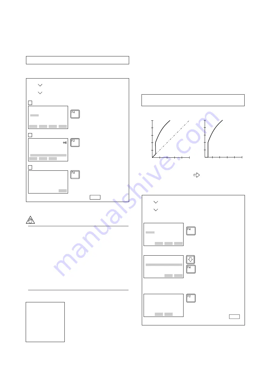
(6) Output Signal Low Cut Mode Setup

Low cut can be used on the output signal to stabilize
the output near the zero point.

The low cut point can be set in a range from 0 to 20%
of output. (Hysteresis of cut point: ±1%)

Either 

LINEAR

 or 

ZERO

 can be selected as the low

cut mode.

Unless otherwise specified, the cut mode is set to
LINEAR at the factory.

(%)

50

(%)

50

0

50

(%)

50

(%)

Output

Output

For low cut in linear mode

Input

20

20

0

For low cut in zero mode

Input

F0216.EPS

Example: To set the low cut range to 20% and the cut mode 

to ZERO, proceed as follows:

Figure 2.2.2 Low Cut Mode

F0217.EPS

EJA:
Low cut
 10.00%
 10.00

HELP

DEL

ESC

ENTER

Call up the Low cut, and set to 
20%.

(ENTER)

(ENTER)

‘2 0’

EJA:
Cut mode
Linear
 Linear
 Zero

HELP

SEND

ESC

ENTER

Select the Cut mode, and set to 
Zero.

EJA:
Basic Setup
 4 Device information
 5 Xfer fnctn Linear
 6 Damp         0.50s
 7 Low cut    20.00 % 
 8 Cut mode      Zero

DEL

SEND

HOME

OK

Press SEND (F2) to send the date, 
then check to confirm that    
disappears.

(SEND)

1. Device setup

3. Basic setup

7. Low Cut, 8. Cut mode

SEND

Содержание Dpharp vigilantplant EJA Series

Страница 1: ...User s Manual Yokogawa Electric Corporation Model EJA Series HART Protocol IM 01C22T01 01E IM 01C22T01 01E 7th Edition...

Страница 2: ...ion 2 5 2 3 2 Menu Tree 2 6 2 3 3 Setting Parameters 2 7 1 Tag No 2 7 2 Unit 2 7 3 Range Change 2 7 4 Output Mode Linear Sq root 2 8 5 Damping Time Constants 2 9 6 Output Signal Low Cut Mode Setup 2 9...

Страница 3: ...110 EJA120 IM 01C22B01 01E EJA210 EJA220 IM 01C22C01 01E EJA310 EJA430 IM 01C22D01 01E EJA118W EJA118N EJA118Y IM 01C22H01 01E EJA438W EJA438N IM 01C22J01 01E EJA115 IM 01C22K01 01E T01 EPS Manual No...

Страница 4: ...adjustment will return the adjustment back to the previous settings Using the HART Communicator Zero point can be adjusted by simple key operation of the HART Communicator Select parameter Zero Trim a...

Страница 5: ...smitter output 1383 mmH2O DPharp F0103 EPS 1 1 Device setup 2 Diag Service 3 Calibration 3 Sensor trim 2 Lower Sensor Trim EJA Apply low pressure ABORT OK F0104 EPS Check the tank level at present and...

Страница 6: ...e setting push button The integral indicator then displays LSET 3 Apply a pressure of 0 kPa atmospheric pressure to the high pressure side of the transmitter Note 1 4 Turn the external zero adjustment...

Страница 7: ...ging LRV automatically changes URV to the following value URV previous URV new LRV previous LRV 3 If the range setting push button and external zero adjustment screw are not touched during a range cha...

Страница 8: ...from any terminal strip as well DPharp HART communicator Relaying terminals Distributor Control room Terminal board F0201 EPS HART communicator Figure 2 1 1 Interconnection Diagram 2 1 2 Communicatio...

Страница 9: ...s the position where a number or character is to be entered Pressing calls up the display corresponding to the item pointed with the highlighting cursor Pressing returns to the previous display See 2...

Страница 10: ...re establish communication EXIT leave the current menu YES answer to yes no question ALL include current Hot Key item on Hot Key Menu for all devices F2 ON OFF activates or deactivates a binary variab...

Страница 11: ...is held in memory unless power is turned off every data can be sent to the transmitter at once Operation Entering data on the Tag setting display 1 Device setup 3 Basic setup 1 Tag F0206 EPS EJA YOKO...

Страница 12: ...f self test calibration of transmitter Display the status of 4 to 20 mA DC output when a failure Display set the external volume protect permit for LRV URV setting Setting a new password Set the curre...

Страница 13: ...m Point 1 Sensor Temperature 2 Sensor Temperature Unit 1 Static Pressure 2 Static Pressure Unit 1 PROCESS VARIABLES 2 RERANGE 3 Unit 4 Transfer Function 5 Damp 6 Low Cut 7 Cut Mode 8 Bi dir Mode 9 H2O...

Страница 14: ...R 3 Select the desired engineering unit and press ENTER F4 HELP 3 ENTER Example To change the unit from mmH2O to inH2O F02111 EPS EJA keypad input 1 LRV 0 00 mmH2O 2 URV 3000 00 mmH2O 3 Unit inH2O 4 L...

Страница 15: ...ABORT OK 3 Apply the pressure of 500mmH2O After obtaining a stable pressure press OK F4 ENTER OK OK 1 Device setup 3 Basic setup 3 Re range 2 Apply values Example To change the range from 0 to 2500 m...

Страница 16: ...circuit The damping constant of the capsule assembly shall be added to obtain the overall damping constant of the transmitter Table 2 0 2 Sec 0 5 Sec 1 0 Sec 2 0 Sec 4 0 Sec 8 0 Sec 16 0 Sec 32 0 Sec...

Страница 17: ...display Low Cut 4 mA 100 display Output mode SQUARE ROOT LRV HRV 8 Integral Indicator Display Mode F0220 EPS ENTER EJA Display fnctn Linear Linear Square Root HELP SEND ESC ENTER Select Square Root a...

Страница 18: ...ing units to be displayed on the HART communicator When the instrument is shipped this is set as specified in the order Follow the procedure below to change this setting Since these units are not disp...

Страница 19: ...nit from mmH2O to kPa inH2O inHg ftH2O mmH2O mmHg psi bar mbar g cm2 kg cm2 Pa kPa torr atm 12 Test Output This feature can be used to output a fixed current from 3 2 mA 5 to 21 6 mA 110 for loop chec...

Страница 20: ...or zero shifts caused by static pressure See section 1 1 1 1 F02281 EPS Select the Lower Sensor trim EJA Sensor trim 1 Zero trim 2 Pres 3 Lower sensor trim 4 Upper sensor trim 5 Sensor trim points HE...

Страница 21: ...000 HELP ESC 5 Enter the read value 4 115 of the ammeter and press ENTER F4 The output of the transmitter changes DEL ENTER ENTER 4 1 1 5 Example 1 For the adjustment using an ammeter 1 A is measurabl...

Страница 22: ...Connect reference meter DEL SET ABORT OK 7 Connect the voltmeter and press OK F4 EJA Setting fld dev output to 4mA HELP DEL ABORT OK 8 Press OK F4 The output signal of 0 is output OK OK ENTER F0233 EP...

Страница 23: ...lay and set to OFF 16 Multidrop Mode Multidropping transmitters refers to the connection of several transmitters to a single communications transmission line Up to 15 transmitters can be con nected wh...

Страница 24: ...zero adjustment screw on the transmitter This is set to ENABLE when the instrument is shipped F0237 EPS ENTER EJA Ext SW mode Enable Enable Inhibit HELP SEND ESC ENTER Select Inhibit and press ENTER...

Страница 25: ...s Write Protect status for 10 minutes While Write Protect status is released enter a new password in the New Password field It will not be possible to set a new password when 10 minutes have elapsed 2...

Страница 26: ...select F0241 EPS ENTER EJA H2O Unit select 4C 4C 20C 68F HELP SEND ESC ENTER Select 20C 68F and press ENTER F4 Press SEND F2 to send data SEND 1 Device setup 4 Detailed setup 2 Signal condition 9 H2O...

Страница 27: ...o low Operation is set in the Write Protect mode Value is set to a nearest possible value LRV set point is too high LRV set point is too low URV set point is too high URV set point is too low Set span...

Страница 28: ...modify as needed Check URV and modify as needed Check SPAN and change as needed Readjust zero point Replace capsule Replace amplifier Check input Integral Indicator Display Description Cause Counterme...

Страница 29: ...Pressure variable output variable 4 to 20 mA output variable Sensor temperature Static pressure Output in Engr unit Test output setting Self test Status Status of analog output alarm Write Protect En...

Страница 30: ...emote seal Remote seal fill fluid Remote seal type Distributor Device type Device ID Final assembly number Universal revision Fld dev revision Software revision Model Style Lower range limit Upper ran...

Страница 31: ...nts and the associated page numbers may not coincide with the one in old edition Add Hardware Write Protect and Burnout Direction with optional code F1 REVISION RECORD EPS 4th July 2000 ii 2 6 2 18 3...

Отзывы: