background image

5-9

IM AQ1200-01EN

W

aveform Display

10 

11 

12 

13 

14 

15 

16 

17 

18

19 

App 

Index

20

Ghost Cursors

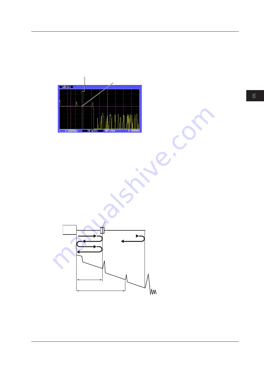
Ghost cursors are used to check for secondary reflections. A secondary reflection is a reflection that is 
detected in a location where no event actually occurs.

Off:  Ghost cursors are not displayed.
On:  Ghost cursors are displayed.


Ghost cursor 

Turn the rotary knob to move to the next secondary reflection detection point. 

Secondary reflection 

How Secondary Reflections Are Generated

  The optical pulse that is generated from position I in the following figure propagates in the direction 

of II.

    ↓

  Light ray A that is reflected at connection II is reflected again at connection I and propagates in the 

direction of II as light ray B.

  At this point, the Instrument detects A as an event.

    ↓

  B is again reflected by connection II, and this generates reflected light ray C. At this point, the 

Instrument detects C as an event.

  Because the Instrument measures all the reflected light rays, A, C, and D, C is also detected as 

an event in the same manner that an actually generated reflection is. Therefore, while there is no 
actual event in this location, it appears as if an event has in fact occurred.


Distance 2L 

Distance L 

Optical fiber cable connection 

II 

III 

5.5  Setting the Waveform Information Display

Содержание AQ1200A

Страница 1: ...User s Manual AQ1200A AQ1200B AQ1200C AQ1200E AQ1205A AQ1205E AQ1205F OTDR Multi Field Tester IM AQ1200 01EN 8th Edition...

Страница 2: ...M AQ1200 92Z1 A document for China The EN in the manual number is the language code Contact information of Yokogawa offices worldwide is provided on the following sheet Document No Description PIM 113...

Страница 3: ...r cautions de s curit pouvant pr venir de tels accidents ATTENTION Attire l attention sur des gestes ou des conditions susceptibles de provoquer des blessures l g res ou d endommager l instrument ou l...

Страница 4: ...Chapter 3 Optical Pulse Measurement and Analysis Conditions 3 1 Selecting the Measurement Mode 3 1 Simple Full Auto Mode 3 2 Selecting the Wavelength 3 3 3 3 Automatically Saving Measured Data 3 4 3 4...

Страница 5: ...ements 9 1 9 2 Setting Optical Power Measurement Conditions and Holding the Display 9 2 9 3 Logging Measured Values and Saving Logged Results 9 5 9 4 Selecting and Saving Core and Tape Numbers 9 10 Ch...

Страница 6: ...Start Menu USB Function and Screen Color 19 1 19 2 Configuring Power Save Settings 19 2 19 3 Resetting the Instrument to Its Factory Default Settings 19 3 19 4 Setting Operation Restrictions 19 4 19 5...

Страница 7: ...surement in cable installations AQ1200x AQ1205x Consumer Corporate user OTDR Features Optical pulse measurement Real time averaged measurement Waveform display Can be zoomed and moved Waveform analysi...

Страница 8: ...measurement of the optical power of different signal wavelengths 1310 nm 1490 nm and 1550 nm of a PON system Multi Core Fiber Measurement Using screens and menus specific to multi core fiber measurem...

Страница 9: ...e optical wavelength and turn the automatic saving of measured data on and off All other measurement conditions are automatically configured or are fixed Detail In this mode you can set all measuremen...

Страница 10: ...on During averaged measurement you cannot change the measurement conditions You can stop the averaged measurement before it completes Multi Core Fiber Measurement Using screens and setup menus specifi...

Страница 11: ...nnector Loss caused by bending Reflection at the open end of the fiber Fresnel reflection Dynamic range SNR 1 Optical fiber Near end Reflection This is the reflection that occurs at the point where th...

Страница 12: ...cident optical power 14 7 dB is reflected Glass Air Incident ray 100 Reflected light 3 Light 97 Dynamic Range Dynamic range refers to the range of optical power levels that can be measured The larger...

Страница 13: ...he correct index of refraction is not specified there will be errors in the distance measurement Setting the Index of Refraction The AQ1200x AQ1205x has preset indices of refraction that correspond to...

Страница 14: ...that occur at connections cannot be detected If you are measuring a short distance connect a dummy fiber to move events that are hidden in the near end reflection the distance of the dummy fiber Do no...

Страница 15: ...end point n a point N that is used to calculate the near end side s approximated line a point E where splice loss is detected a point F that is used to calculate the far end side s approximated line...

Страница 16: ...e events of the other trace that exists within 6 of the position of an event of the current trace the closest event will be considered part of the current trace event Traces that meet the following co...

Страница 17: ...return loss can be recalculated S 1 2 E Measurement reference point Event number 1 Event number 2 Detected fiber end event E Event List Editing You can set indices of refraction for each event period...

Страница 18: ...able for measuring different types of optical power Item Models with SLT or HLT Suffix Codes Models with SPM Suffix Codes Models with PPM Suffix Codes Normal power meter selected PON power meter selec...

Страница 19: ...lue to measured optical power values 9 You can set upper and lower threshold values and determine whether or not the measured values fall within them 10 You can measure the optical power of an upstrea...

Страница 20: ...s can be specified or executed For details about these items see section 1 5 The unit reference offset and threshold values can be specified The zero set and measured value display hold operations can...

Страница 21: ...ically transferred Connecting the Optical Fiber under Loss Test All fibers other than the optical communication fiber can be tested For each optical fiber under loss test connect one end to the master...

Страница 22: ...ss level that is used to determine whether this is the fiber end face or not Break fault You can make measurements on the selected route The following five routes are available Normal Searches for fau...

Страница 23: ...1 9 Checking Fiber End Faces You can use a fiber inspection probe to take a photograph that shows the state of a fiber end face You can display this photograph on the AQ1200x AQ1205x screen and save...

Страница 24: ...fiber or line is connected physically IP testing is available on models with the LAN option Ping Test To ping an address perform a simple IP test specify the address and configure the Tx frame settin...

Страница 25: ...ent you can measure cores under the same conditions You can save projects to files You can load a previously saved project and make measurements under the same conditions List Cores are listed You can...

Страница 26: ...ing on the results of pass fail judgments Near end reflection Splice loss Reflection caused by a connector Loss caused by bending Reflection at the open end of the fiber Fresnel reflection Reflection...

Страница 27: ...Startup menu selection USB function selection storage communication Screen color selection Current date and time configuration see the operation guide IM AQ1200 02EN Power save settings Network settin...

Страница 28: ...robe Fault Locator Visible Light Source PON_OPM Multi Core Fiber Meas OTDR Event Mapper Top Menu Displays an image that shows the selected feature Rotary knob ENTER key The center of the rotary knob D...

Страница 29: ...ls see section 19 1 OTDR Top Menu If you select the OTDR feature from the top menu the OTDR menu OTDR top menu will appear On AQ1200x AQ1205xs with firmware version 2 03 and later the OTDR top menu va...

Страница 30: ...switching to waveform analysis commands During real time measurement measurement condition setting commands appear When real time measurement finishes the menu will change to displaying waveform analy...

Страница 31: ...rement When not measuring During averaged measurement After averaged measurement Average duration command see section 3 5 Switches to waveform analysis commands Marker command Displays clears snapshot...

Страница 32: ...ted operation is executed the selected item is confirmed or the operation is executed Soft keys MENU MENU ESC ESC In this manual the above key operation is described as shown below Example of an Expla...

Страница 33: ...tailed operations for proceeding to the desired setup menu or dialog box and information about the accompanying screen changes Step numbers are used in soft key explanations when there are many operat...

Страница 34: ...cted item to its previous setting press ESC To increase or decrease a value use the rotary knob or the up and down arrow keys To move between digits use the left and right arrow keys Press ENTER to co...

Страница 35: ...re Also you can only make shortcut assignments when you are using the OTDR feature The shortcut feature does not function on the top screen You can assign the same action to both the rotary knob and t...

Страница 36: ...action assigned Displays the file menu Displays the print menu Displays the scale menu Displays the visible light source menu Starts saving Starts printing Coarse Fine Switches the resolution between...

Страница 37: ...tered and close the character input dialog box The string be applied to the relevant item You can also confirm the string by moving the cursor to ENT on the displayed keyboard and then pressing ENTER...

Страница 38: ...y knob and ENTER select to display the input history screen 2 Using the rotary knob and ENTER choose the string that you want to enter The string appears in the edit screen Note Entered strings are sa...

Страница 39: ...rument is in Simple Full Auto mode are listed below You can view these conditions in the measurement condition information see section 5 1 that is displayed on the screen Item Setup Distance range Aut...

Страница 40: ...splitter stages 1 2 Image when the route is set to ONU OLT Select the number of splits from the following 2 4 8 16 32 64 128 The maximum total number of splits is 128 Set the route OLT ONU or ONU OLT...

Страница 41: ...en 1 Using the rotary knob and ENTER select OTDR 2 Press SETUP and then the Meas Setup soft key 3 Using the rotary knob and ENTER set Mode to Simple to display the following screen Set Mode to Simple...

Страница 42: ...nob and ENTER select OTDR 2 Press SETUP and then the Meas Setup soft key 3 Using the rotary knob and ENTER set Mode to Simple to display the following screen Turns automatic saving of the measured res...

Страница 43: ...Method Marker Simple Full Auto Mode Procedure Analysis Setup Screen 1 Using the rotary knob and ENTER select OTDR 2 Press SETUP and then the Analysis Setup soft key 3 Using the rotary knob and ENTER s...

Страница 44: ...interval Normal High Resolution 5cm 10cm 20cm 50cm 1m 2m 4m 8m 16m 32m Set the average count or the duration to average over When the unit is times Auto 2 10 2 11 2 12 2 13 2 14 2 15 2 16 2 17 2 18 2...

Страница 45: ...00A AQ1200B AQ1200C and AQ1205A the light for a single mode SM optical fiber is emitted from optical port 2 On the AQ1200E AQ1205E and AQ1205F light with a 1310 nm or 1550 nm wavelength is transmitted...

Страница 46: ...m 3 ns 10 ns 20 ns 50 ns 100 ns 200 ns 500 ns 1 km 3 ns 10 ns 20 ns 50 ns 100 ns 200 ns 500 ns 1 s 2 km 3 ns 10 ns 20 ns 50 ns 100 ns 200 ns 500 ns 1 s 5 km 3 ns 10 ns 20 ns 50 ns 100 ns 200 ns 500 ns...

Страница 47: ...eed In Hi Speed mode all sections are measured according to the specified attenuation If the specified attenuation value is not appropriate and a large reflection occurs the waveform for that section...

Страница 48: ...verage unit If Auto is selected one of the options above is used Event Search The event search is a feature that automatically searches for losses and reflections in the data that is acquired during a...

Страница 49: ...age see section 19 2 On the AQ1200B and AQ1200C because the light received at the wavelength for optical communication is blocked not detected fiber in use alarms do not occur Plug Check The plug chec...

Страница 50: ...e event s splice loss 0 01dB to 9 99dB Set the event s return loss 20dB to 70dB Set the end of fiber Fresnel reflection 3dB to 65dB Turns splitter detection on or off Threshold for splitter detection...

Страница 51: ...orrect The Instrument has the following preset backscattering light levels that correspond to each wavelength 1310 nm 50 dB 1550 nm 52 dB 1625 nm 53 dB 1650 nm 53 dB You can specify a value from 10 00...

Страница 52: ...loss that is less than or equal to the specified threshold occurs it is detected as an event The larger the reflection the smaller the return loss so events reflections are detected when the return l...

Страница 53: ...e displayed with an asterisk attached to them Splice Loss and Return Loss Set the threshold values that are used to display events as faults Splice loss The range is 0 01 dB to 9 99 dB Return loss The...

Страница 54: ...g loss Detection of a bending loss Move the cursor to a bending loss event to display the values 1550 nm wavelength 1310 nm wavelength Bending loss events are displayed in this event list In this exam...

Страница 55: ...1625 nm or 1650 nm optical pulse wavelengths Even though these differ from the wavelength for optical communication if communication light is present in the optical fiber the fiber is in use the comm...

Страница 56: ...e Turns the alarm notification upon work completion on or off Turns the message display upon work completion on or off Explanation Before you check whether the work is complete move the cursor to the...

Страница 57: ...strument checks the work completion a message confirming whether you have set the cursor to a position that is a little after the installation point is displayed No Check The confirmation message is n...

Страница 58: ...ss Cumulate loss The integrated value of the splice losses at each event from the measurement reference point S is displayed This is the conventional calculation method firmware version 2 05 and earli...

Страница 59: ...s Include END The value is included in the total return loss Exclude END The value is not included in the total return loss S 1 2 E E E E Measurement reference point Event number 1 Event number 2 END...

Страница 60: ...OR format For details on the File Name Setup screen see section 18 2 Label The text entered in Label when the Label Setup screen was opened from the File Name Setup screen is displayed as the label th...

Страница 61: ...l Pulse Measurement and Analysis Conditions 3 2 1 4 5 6 7 8 9 10 11 12 13 14 15 16 17 18 19 App Index 20 Shows the label at the bottom of the screen only when Label Setup is set to Label 3 10 Selectin...

Страница 62: ...r les mod les d au moins deux orifices de source lumineuse une d ficience visuelle peut se produire si la lumi re mise par erreur du mauvais orifice p n tre dans l il Procedure Starting and Stopping M...

Страница 63: ...work completion confirmation ON OFF Explanation Real time Measurement Measurement conditions are set before the actual measurement takes place but during real time measurement you can change the measu...

Страница 64: ...splays a message on the screen or sounds an alarm For details see section 3 8 Fiber end Move the cursor to a position that is a little after the installation point Example When the planned installatio...

Страница 65: ...e la lumi re est mise travers les ports de source lumineuse Ne pas d brancher les c bles de fibre optique connect s Des l sions oculaires peuvent tre caus es si le faisceau lumineux p n tre l il Masqu...

Страница 66: ...s automatically If you set Avg Duration to Auto the duration to average over is displayed at the top of the screen If you specify a setting other than Auto a value that indicates the progress is displ...

Страница 67: ...When you are in the event analysis menu only the current trace is displayed When you finish event analysis the multi wavelength trace display returns Disabling of the Multi Wavelength Trace Display In...

Страница 68: ...entarily and a snapshot waveform appears The text displayed on the soft key changes from Snapshot to Clear Snapshot Take clear a snapshot If you press this soft key when Snapshot is displayed a snapsh...

Страница 69: ...he distance reference is 0 and this displays the distance from the distance reference to the position of the left edge of the screen as a negative value Distance per division on the horizontal axis Wa...

Страница 70: ...nd horizontal directions See section 5 3 Set the amount the cursor moves Fine Coarse Set whether to move the cursor a small amount or a large amount Auto Zoom Automatically zooms in on the waveform at...

Страница 71: ...t the left edge of the display Down arrow key Zoom in on the waveform in the vertical direction Up arrow key Zoom out on the waveform in the vertical direction Left arrow key Zoom in on the waveform i...

Страница 72: ...displayed Overview Display The overview display is linked to the zoomed waveform display The blue box indicates where in the entire waveform display area the zoomed waveform display is showing When th...

Страница 73: ...ates where in the entire waveform display area the currently displayed waveform area is Executes auto zoom See section 5 2 Moving the Displayed Waveform 1 Press the arrow keys to move the displayed wa...

Страница 74: ...ay the following screen Initializes the display scales Enables zooming See section 5 2 Enables moving in the vertical and horizontal directions See section 5 3 Executes auto zoom See section 5 2 Set t...

Страница 75: ...he marker information display on or off Turns the event auto zoom on or off Turns the scale display on or off Turns the tooltip display on or off Turns the cursor dB value display on or off Set the pu...

Страница 76: ...ss are measured Each value is calculated in real time as you move the line marker Marker Line Note Line is often used outside of Japan Marker is often used within Japan It is used on existing YOKOGAWA...

Страница 77: ...owing figure propagates in the direction of II Light ray A that is reflected at connection II is reflected again at connection I and propagates in the direction of II as light ray B At this point the...

Страница 78: ...mation is not displayed On Marker information is displayed Marker information Event Auto Zoom When events have been detected you can zoom in on the event at the cursor position or the selected event E...

Страница 79: ...Uses a crosshair to indicate a position on the waveform Line Uses a line to indicate a position on the waveform Crosshair display Line display Event List In event analysis you can select which items t...

Страница 80: ...ction that the cursor moves differs depending on the direction that you rotate the rotary knob Clockwise The cursor moves to the right Counterclockwise The cursor moves to the left If you turn the rot...

Страница 81: ...ve the measurement reference point Switches to the screen that is used to delete markers and the cursor A marker measurement outline is displayed on the screen For details see Explanation later in thi...

Страница 82: ...rker 1 1 Press to set all markers together See Distance Reference later in this section See Distance Reference later in this section 1 2 3 Note Set the markers in the order shown above starting with t...

Страница 83: ...ix code is HE press the Analysis soft key and then the Marker soft key Press to switch to the screen that is used to measure the two point markers See 2 Point later in this section Press to switch to...

Страница 84: ...set them so that the n marker is the measurement start point the distance reference 5 Point Markers 3 Press the 5 Point Markers soft key shown on the previous page to display the following screen Pre...

Страница 85: ...details on the approximation methods see section 3 6 4 Point Markers This mode is only enabled when the Marker Mode is set to Marker The Instrument uses the following four points to perform the measur...

Страница 86: ...Approximated line F f Approximated line n N E Splice loss Return loss b c b c dB km dB km a dB e n E E f f e f dB km dB km The measured loss value differs depending on the specified approximation met...

Страница 87: ...the cursor see section 6 1 The location where the Instrument and the optical fiber are connected is the distance reference To perform more accurate measurements zoom in on the waveform Using Markers...

Страница 88: ...stance Ref Setup soft key to display the following screen When the suffix code is HE press the Analysis soft key the Marker soft key and then the Distance Ref Setup soft key 3 Turn the rotary knob to...

Страница 89: ...r 3 Measured splice loss result When Marker Mode Is Set to Line 1 Using the rotary knob and ENTER select OTDR 2 Press the Marker soft key and then the 5 Point Markers soft key to display the following...

Страница 90: ...nt detects the peak between the markers and calculates the level between the peak and the rising start point of the event When Marker Mode Is Set to Line 1 Using the rotary knob and ENTER select OTDR...

Страница 91: ...value shown To prevent a waveform from being saturated you can Select a large attenuation value and perform the measurement again Select Hi Reflection for the average method and perform the measureme...

Страница 92: ...oaded trace down Clears the displayed traces Clears the display of the loaded traces Selects the current trace Trace 1 Trace 2 Trace 3 Trace 4 Explanation Loading Trace Data Up to four traces can be l...

Страница 93: ...alysis appears Load traces to display in Trace 1 and Trace 2 The file operation screen appears see section 17 2 Screen Trace List List See section 7 1 Display type Reverse Normal Selects the rotary kn...

Страница 94: ...trace end A end B Bottom trace end A end B Distance reference 0 m position of the bottom trace End point of the top trace 1 2 2 3 As shown in the above figure markers are added only to the trace in w...

Страница 95: ...race analysis screen appears Load traces to display in Trace 1 and Trace 2 The file operation screen appears see section 17 2 When marker mode is set to Marker When marker mode is set to Line Explanat...

Страница 96: ...an place cursors and markers on the differential trace You can display the distance at each cursor position as well as the following values between markers Loss dB Distance km dB km For the operations...

Страница 97: ...arkers When the and markers or the n and E markers are already present change these markers to the start point and end point markers 1 2 Press to configure more settings See Adjusting the Reference Le...

Страница 98: ...S and E markers are displayed on the screen Marker Auto Setup You can automatically set marker 1 or marker n as the start point and marker 2 or marker E as the end point You can use this feature to au...

Страница 99: ...vents see section 7 2 Select the rotary knob function Cursor Event Press to configure the two point markers See 2 Point Markers later in this section For details on the two point markers see section 6...

Страница 100: ...The distance from the measurement reference point to each event is displayed If you move the distance reference which is the measurement reference point the distance from the distance reference to eac...

Страница 101: ...isplayed in the following manner depending on the total loss calculation method Cumulate loss The integrated value of the splice losses at each event from the measurement reference point S is displaye...

Страница 102: ...o display the following screen When the suffix code is HE press the Analysis soft key the Event Analysis soft key and then Event Edit Fix soft key Inserts an event You can insert events when Cursor is...

Страница 103: ...r to the event that you want to edit The selected event s color changes 5 Press the Event MarkerEdit soft key The Event MarkerEdit menu appears and event markers are displayed When Marker Mode Is Set...

Страница 104: ...you insert an event to the right of the E event the inserted event becomes the E event and a new number is assigned to the former E event Deleting Events If only the S point and the E event are displa...

Страница 105: ...e Is Set to Mode1 Events detected at positions other than the master event positions are displayed in the event list Events other than fixed events are also detected An earlier event is detected so th...

Страница 106: ...Editing Distances When you change the distance of an event the section group index section IOR is recalculated When you change the distance of an event but the event cannot be set at the specified po...

Страница 107: ...re la lumi re est mise travers les ports de source lumineuse Ne pas d brancher les c bles de fibre optique connect s Des l sions oculaires peuvent tre caus es si le faisceau lumineux p n tre l il Masq...

Страница 108: ...to indicate that the light is on Turns the light off The light turns off The light mark disappears Explanation This feature is available on models with the SLT HLT PPM or SLS option Loss Measurement...

Страница 109: ...ce Option 3 2 1 4 5 6 7 8 9 10 11 12 13 14 15 16 17 18 19 App Index 20 8 1 Producing Measurement Light Modulation Mode You can set the frequency of the light to one of the following options CW continu...

Страница 110: ...c bles de fibre optique connect s Des l sions oculaires peuvent tre caus es si le faisceau lumineux p n tre l il Masquer les orifices de source lumineuse sur lesquels aucun c ble fibres optiques n est...

Страница 111: ...wing screen The wavelength and modulation mode of the emitted light Set the modulation mode CW 270Hz 1kHz 2kHz Set the wavelength The available settings vary depending on the models Turns the light on...

Страница 112: ...ght turns on A mark appears on the instrument display to indicate that the light is on Turns the light off The light turns off The light mark disappears Laser on indication Light mark Explanation The...

Страница 113: ...ro Set 1 Using the rotary knob and ENTER select LS_OPM the power meter light source 2 Press SETUP and then the OPM Setup soft key to display the following screen Performs zero set Explanation This fea...

Страница 114: ...de CW 270Hz 1kHz 2kHz Set the unit dB dBm W Set the reference manually 80 to 40 dBm The Reference box appears if you press the DREF soft key or set the unit to dB see the detailed setup screen in sect...

Страница 115: ...optical power display unit to one of the following options dB relative value dBm absolute value W absolute value The following prefixes are attached to W m 10 3 10 6 n 10 9 and p 10 12 The relationsh...

Страница 116: ...settings This feature is available on models with the SLT HLT or PPM option On After On is selected the power meter settings are synchronized to the light source settings Off The power meter settings...

Страница 117: ...Save screen described below Screen display items Logging 3 Press the Display soft key to select Logging The following screen appears Date and time See the operation guide IM AQ1200 02EN Cursor Value p...

Страница 118: ...ff Displaying and Moving the Cursor 5 Turn the rotary knob to display the cursor Cursor Note The direction that the cursor moves differs depending on the direction that you rotate the rotary knob Cloc...

Страница 119: ...17 2 Saves the data Set the destination drive internal memory USB memory Explanation This feature is available on models with the SLT HLT or PPM option Creating and Saving Logs The Instrument is alwa...

Страница 120: ...cause the sections that are outside of the measurement range cannot be displayed even if you switch to the other cursor the selected cursor will not be displayed in the center of the screen Auto Zoom...

Страница 121: ...graph display vertically Vertical zoom factor 50 Press the left arrow key to zoom the graph display horizontally Horizontal zoom factor 10 Overview Display The overview display is linked to the zoomed...

Страница 122: ...set as the save destination is highlighted Set the list to show Core List List Data measurement conditions and measured values The data set in section 9 2 is displayed Save area Save area When Display...

Страница 123: ...to a h 8 Set the tape number type Off a b 2 a c 3 a d 4 a e 5 a f 6 a g 7 a h 8 Saving Data to a File Press SETUP and the File soft key Or press SETUP twice The file save screen appears Follow the pr...

Страница 124: ...ng Skip on cores that do not need to be measured you can save time Saving Data You can save up to three sets of data in the save area of the specified core For details about saving the data to a file...

Страница 125: ...then start the PON power meter zero set procedure Procedure Performing Zero Set 1 Using the rotary knob and ENTER select PON_OPM PON power meter 2 Press SETUP and then the OPM Setup soft key to displ...

Страница 126: ...r to display the following screen Holds the measured value display Measured value Bar graph display of the measured value Set the signal direction ONU OLT OLT ONU Lower threshold line Upper threshold...

Страница 127: ...rom the ONU optical network unit the user s optical terminal to the OLT optical line termination the telephone exchange s optical terminal The optical power of the 1310 nm data wavelength signal is me...

Страница 128: ...lower threshold value When a measured value is within the upper and lower thresholds its bar graph is green PASS appears in the measured value area When a measured value exceeds the upper threshold or...

Страница 129: ...at is set as the save destination is highlighted Example of the data measurement conditions and measured values when the signal direction is ONU OLT The data set in section 10 2 is displayed Save area...

Страница 130: ...2 a c 3 a d 4 a e 5 a f 6 a g 7 a h 8 Saving Data to a File Press SETUP and the File soft key Or press SETUP twice The file save screen appears Follow the procedure in section 18 2 to save the data Ex...

Страница 131: ...core is not measured By specifying Skip on cores that do not need to be measured you can save time Saving Data You can save up to three sets of data in the save area of the specified core When the si...

Страница 132: ...ber cable because light is emitted from the light source port Visual impairment may occur if the light enters the eye Close the covers of any light source ports that do not have optical fiber cables c...

Страница 133: ...perform the loss test with a single unit Use a model sold separately that has a light source whose wavelength is compatible such as the AQ1200A or AQ1100 series Zero Set Perform zero set whenever nec...

Страница 134: ...measured value Set the reference manually 80 to 40 dBm The Reference box appears if you press the DREF soft key or set the unit to dB Sets the reference to the currently displayed measured value Holds...

Страница 135: ...emitted from the light source port Visual impairment may occur if the light enters the eye Close the covers of any light source ports that do not have optical fiber cables connected to them On models...

Страница 136: ...tup screen on the next page you can set the starting core number tape number type and number of fibers Core no Check mark indicating that the data has been saved Skipped core numbers are dimmed The co...

Страница 137: ...p to 12 tapes when Tape no Type is set to a h 8 Set the tape number type Off a b 2 a c 3 a d 4 a e 5 a f 6 a g 7 a h 8 Saving Data to a File Press SETUP and the File soft key Or press SETUP twice The...

Страница 138: ...tical fiber to the port that the light with the selected wavelength will be transmitted from Executing an Auto Loss Test To perform loss testing configure the settings for the optical power meter and...

Страница 139: ...gth The available settings vary depending on the models Measured value Bar graph display of the measured value Set the reference manually 80 to 40 dBm The Reference box appears if you press the DREF s...

Страница 140: ...lumi re la lumi re est mise travers les ports de source lumineuse Ne pas d brancher les c bles de fibre optique connect s Des l sions oculaires peuvent tre caus es si le faisceau lumineux p n tre l il...

Страница 141: ...Holding of the Display of Measured Values For information about the unit reference offset threshold values and the holding of the display of measured values see Explanation in section 9 2 Light Source...

Страница 142: ...of fibers or tapes up to 100 fibers when Tape no Type is set to Off up to 50 tapes when Tape no Type is set to a b 2 up to 12 tapes when Tape no Type is set to a h 8 Set the wavelength The available...

Страница 143: ...Light Wavelength AQ1200A SM 1310 nm SM 1550 nm AQ1200B SM 1625 nm AQ1200C SM 1650 nm AQ1200E SM 1310 nm SM 1550 nm SM 1625 nm AQ1205A SM 1310 nm SM 1550 nm AQ1205E SM 1310 nm SM 1550 nm SM 1625 nm AQ1...

Страница 144: ...ight source ports visual impairment may occur if light that is mistakenly emitted from the wrong port enters the eye French AVERTISSEMENT Lorsque l AQ1200x AQ1205x g n re de la lumi re la lumi re est...

Страница 145: ...ey to select Slave The following menu appears Slave Master Loss Test Screen Loss Test Screen On the menu Project Transmission START changes to Project Transmission STOP After transmission finishes Pro...

Страница 146: ...e communication fiber that you specified to the master s light source port and connect the other end to the slave s optical power measurement port Prepare the slave to receive the project information...

Страница 147: ...impairment may occur if the light enters the eye Close the covers of any light source ports that do not have optical fiber cables connected to them On models with two or more light source ports visua...

Страница 148: ...oss Test START Specify skipping as necessary Slave 4 Connect to the light source port the optical fiber that corresponds to the core number transmitted from the master It may take time to receive the...

Страница 149: ...s Follow the procedure in section 18 2 to save the data Explanation This feature is available on models with the SLT or HLT option Multi core loss testing is performed while information such as projec...

Страница 150: ...lumineuse Ne pas d brancher les c bles de fibre optique connect s Des l sions oculaires peuvent tre caus es si le faisceau lumineux p n tre l il Masquer les orifices de source lumineuse sur lesquels a...

Страница 151: ...trument returns to the previous screen During adjustment Execute changes to Abort All soft keys other than the Abort soft key are unavailable Press the Abort soft key to stop optical power adjustment...

Страница 152: ...his to search the routes from the OLT through the splitter to each ONU OLT Splitter Select this to search the route from the OLT to the splitter Normal Select this to search for faults in the fiber th...

Страница 153: ...isplay screen See section 5 1 Cursor position See section 6 1 Measurement Screen 3 Press SETUP to display the following screen Set the wavelength See Explanation in section 3 5 Set the end of fiber Fr...

Страница 154: ...ving measured data see section 18 2 Explanation Select Route Menu Before starting the fault locator feature you can select the route in which to search for breaks After confirming the route press ENTE...

Страница 155: ...to the previous screen Holds the screen Press this soft key to put the screen into the hold state When in the hold state HOLD is displayed at the top of the screen If you press this soft key again the...

Страница 156: ...n Use the Ethernet port to execute a ping test Pinging Target Address Specify the address that you want to ping Tx Frame Set the conditions of the frame you will use for pinging Frame Length You can s...

Страница 157: ...G Stop All soft keys other than the PING Stop soft key are unavailable To stop pinging press the PING Stop soft key PING Stop will change to PING Start Ping Test Results The ping test results are list...

Страница 158: ...e project name of the current project Core number The core number at the cursor location is highlighted Create a new project Specifies skip You can select this soft key when the cell at the cursor loc...

Страница 159: ...nging the measurement core information will cause the following confirmation screen to appear Setting Measurement Conditions Meas Setup Multi Wavelength Screen 4 Press the Meas Setup soft key The foll...

Страница 160: ...tion 3 6 Setting Analysis Conditions Note Depending on the analysis conditions that you change event detection of all fibers may be executed again For details see Changing Analysis Conditions in Expla...

Страница 161: ...Skip Specify Skip for cores that will not be measured Core numbers set to Skip appear dimmed Creating a New Project To create a new project change the project name and create a new project file Projec...

Страница 162: ...mber to one of the following options OFF a b 2 a c 3 a d 4 a e 5 a f 6 a g 7 a h 8 Setting the Number of Fibers in Each Division When Tape No is set to OFF you can set the number of columns shown on t...

Страница 163: ...conditions can be changed while retaining measured data When you change them settings of unmeasured core numbers will change Measurement conditions Event search Auto save Fiber in use alarm Plug check...

Страница 164: ...en you change measurement core information measurement conditions or analysis conditions the project file MPJ extension is overwritten Saving Screen Images Screen images are saved to the file MultiFib...

Страница 165: ...ture for the first time after purchase or if the settings have been initialized NewProject will appear NewProject is an empty project 2 Press SETUP and the File soft key Or press SETUP twice The follo...

Страница 166: ...two or more light source ports visual impairment may occur if light that is mistakenly emitted from the wrong port enters the eye French AVERTISSEMENT Lorsque l AQ1200x AQ1205x g n re de la lumi re la...

Страница 167: ...about the core number at the cursor location Clear the check mark Clears the check mark or the pass fail judgment result indication from the cell at the cursor location and deletes the cell data Spec...

Страница 168: ...een saved The main view screen returns When measured results have not been saved The following screen appears If necessary save the measured results Set the wavelength You can select one of the wavele...

Страница 169: ...hen measurement is complete the measured results are automatically saved The main view screen appears and check marks or pass fail judgment indications appear in the core number cells whose measuremen...

Страница 170: ...the main view screen The preview area at the bottom of the screen displays the measurement conditions measurement date and the measurement result waveform of the selected core number Confirm the wavef...

Страница 171: ...rement the OTDR measurement screen is displayed As with normal OTDR measurements averaged measurement can be performed after real time measurement Real time Measurement During real time measurement of...

Страница 172: ...hose event analysis has not been executed even when the fault event display is turned on If this occurs you can turn off the fault event setting once and then turn it back on so that pass fail judgmen...

Страница 173: ...or later click Batch Conversion and then MPZ Select the source file MPZ file and the conversion destination An MPJ file and SOR files will be extracted AQ7932 sold separately is a PC software applica...

Страница 174: ...the screen display item Map List Confirm the waveform You can confirm the waveform of the event that is specified by the cursor Set the wavelength The available options vary depending on the model For...

Страница 175: ...French AVERTISSEMENT Lorsque l AQ1200x AQ1205x g n re de la lumi re la lumi re est mise travers les ports de source lumineuse Ne pas d brancher les c bles de fibre optique connect s Des l sions ocula...

Страница 176: ...tion 3 5 Overview display The position of the selected event is indicated with a marker Note To stop the averaged measurement in progress press AVE The averaged measurement will stop and the screen th...

Страница 177: ...set in the measurement conditions For the procedure see section 7 1 Multi Pulse Width Measurement on models with the HJ suffix code This function uses multiple pulse widths to simultaneously measure...

Страница 178: ...soft key is not displayed on the OTDR menu when executing measurements During measurement averaged measurement of multiple pulse widths is continuously executed Waveform Confirmation Screen The wavefo...

Страница 179: ...esults are displayed Event No Event identification number on the route The numbers are assigned in ascending order from the measurement reference point Distance For details see the explanation in sect...

Страница 180: ...uate in the far end section preventing correct measurement Conversely increasing the pulse width of optical pulse measurement allows correct measurement in the far end section but decreases the measur...

Страница 181: ...m moire USB ou m moire interne ou les donn es qu il contient Use a portable USB storage medium Connect it directly to the USB Type A port on the Instrument Hot plugging is supported you can connect o...

Страница 182: ...have selected a feature other than the multi core loss test from the top screen or top menu Press SETUP and the File soft key Or press SETUP twice The following screen appears Set the action Save Loa...

Страница 183: ...part and of the file name Set the separator _ _ Set the ID number 0 to 9999 Set the tape number type Off a b 2 a c 3 a d 4 a e 5 a f 6 a g 7 a h 8 Set the tape number start character Set within the sp...

Страница 184: ...feature other than the OTDR fault locator or multi core fiber measurement CSV A CSV format measurement data file1 The measurement data including measurement conditions such as the wavelength and offs...

Страница 185: ...One character tape number If you select to use the ID number for the file name when Tape Number Type is set to anything other than Off the tape number is automatically appended to the ID number Examp...

Страница 186: ...LPT5 LPT6 LPT7 LPT8 LPT9 COM0 COM1 COM2 COM3 COM4 COM5 COM6 COM7 COM8 COM9 The following types of characters can be used 0 to 9 A to Z a to z _ and cannot be entered consecutively Make sure that the f...

Страница 187: ...ly display 1000 files and folders There is no way to set which files and folders are displayed About the File Operation Screen Depending on the model and the selected feature the operations for openin...

Страница 188: ...Operation Screen Press SETUP and the File soft key Or press SETUP twice The following screen appears Using the rotary knob and ENTER select the files you want to delete or copy Selected files are ind...

Страница 189: ...eselect changes to All Select All the files in the current folder are deselected Deleting The selected files are deleted Setting the Copy Destination and Copying After selecting the files to copy set...

Страница 190: ...moire interne ou les donn es qu il contient Procedure File Operation Screen Press SETUP and the File soft key Or press SETUP twice The following screen appears Set the action Rename Set the file type...

Страница 191: ...section 18 2 Entering a File Name Enter a file name into the character input dialog box that appears Follow the procedure in section 2 4 Use the character input dialog box to enter the extension as w...

Страница 192: ...s ou charg es partir d une m moire interne Vous risqueriez d endommager le support de stockage m moire USB ou m moire interne ou les donn es qu il contient Procedure File Operation Screen Press SETUP...

Страница 193: ...lder name into the character input dialog box that appears You can use up to 20 characters Follow the procedure in section 2 4 When you press the Commit soft key in the character input dialog box a fo...

Страница 194: ...contient Procedure File Operation Screen Press SETUP and the File soft key Or press SETUP twice The following screen appears Set the action DeleteFolder Copy Folder Using the rotary knob and ENTER se...

Страница 195: ...mory to the USB memory or from the USB memory to the internal memory About the File Operation Screen Depending on the model and the selected feature the operations for opening the file operation scree...

Страница 196: ...u les donn es qu il contient Procedure File Operation Screen Press SETUP and the File soft key Or press SETUP twice The following screen appears Set the action Format Formats the internal memory Expla...

Страница 197: ...select File Print If you select File Print the drive selection menu is displayed Select the drive or the SOR file that you want to print Print Setup Specify the maker of the printer connected to the I...

Страница 198: ...Year month day hour minute second year month day hour minute year short form month day hour minute month day hour minute hour minute Set what to sort by Date File Name Set the sort order A Z Z A Turn...

Страница 199: ...uage Set the language to display on the Instrument screen The options that appear vary depending on the product s language specification Turning the Beep On and Off You can make the Instrument beep wh...

Страница 200: ...turn itself off when the OTDR feature is generating an optical pulse Off The power does not turn off automatically AutoPowerOff 1m The power turns off automatically after one minute AutoPowerOff 5m T...

Страница 201: ...the Measurement Settings All the settings are reset to their factory defaults but the internal memory and the day and time settings excluding the type are not initialized Initializing All Settings All...

Страница 202: ...he rotary knob and ENTER to select Administrator PIN A screen for entering the PIN appears 5 Using the rotary knob and ENTER enter the administrator PIN that you set and then press SET to display the...

Страница 203: ...ng when the Execute soft key for optical power adjustment is pressed light source loop back test While the Instrument is being used as a light source for auto loss testing when the Loss Test START sof...

Страница 204: ...Press SETUP 2 Using the rotary knob and ENTER select Top Menu Func Setup to display the following screen Select the functions when Button Order is set to Fixed Select Use Frequency Order or Fixed Use...

Страница 205: ...il expiration is displayed Setting the Date and Time Expiration Date 3 Using the rotary knob and ENTER select Expiration Date The following screen appears Set the year month and day Setting the Messag...

Страница 206: ...xpiration date is reached a screen indicating that the instrument is locked is displayed at startup 1 Using rotary knob and ENTER select Expiration Release Code 2 Using the rotary knob and ENTER enter...

Страница 207: ...is reached you need to enter a release number when the instrument starts If you do not enter the correct number the instrument will not start Note that if the expiration date arrives while you are usi...

Страница 208: ...data that is stored on the Instrument internal memory For details about the network that you intend to connect the Instrument to contact your network administrator Enabling or Disabling the Network Se...

Страница 209: ...p as described in the previous section Check the information when you access the Instrument from a PC IP Address You can set the IP address assigned to the Instrument The IP address is an ID that is a...

Страница 210: ...equired 20 12 When the temperature of the AQ1200x AQ1205x or its battery pack is high the AQ1200x AQ1205x lowers the LCD brightness automatically to prevent damage Make sure that the temperature of th...

Страница 211: ...between LS port and OPM port 65 Project Information doesn t match between Master and Slave 66 The project sent from master includes an unsuitable wavelength 500 The measurement condition is failed Pl...

Страница 212: ...ierarchy below the specified folder is too deep 637 Folder cannot be deleted The path name is invalid 638 Folder cannot be deleted It failed in the deletion of the file Please confirm the following Me...

Страница 213: ...occurred 818 Test succeeded 854 In USB Storage mode all keys are locked Please disconnect the USB Cable 855 While a measurement is progressed or a file is accessed it cannot go to USB storage mode Ple...

Страница 214: ...stop measuring and wait for a while 916 The temperature inside the instrument is increasing Please stop measuring and wait for a while 917 The temperature inside the instrument is increasing Please s...

Страница 215: ...lay the following screen Saves a screen image Explanation The following information about the Instrument is displayed Model Name Serial Number Suffix Code Mac Address Version Information etc Executing...

Страница 216: ...e Instrument checks the operation of the Internal memory RTC real time clock battery Battery pack voltage Note Perform a self test with the battery pack installed in the Instrument If the battery pack...

Страница 217: ...ware select a firmware update file YMC extension You can change file names except for the extension as necessary For instructions on how to change the file name see section 18 4 When the firmware upda...

Страница 218: ...ollow the instructions on the screen and back up necessary waveform data screen images measurement conditions and other files from the AQ1200x AQ1205x s DATA folder to a folder on a PC Procedure Messa...

Страница 219: ...gers se retrouvent emprisonn s dans les diff rents connecteurs un dysfonctionnement ou un endommagement risque de se produire Si l ajustement de l un des diff rents types de connecteurs n est pas parf...

Страница 220: ...es do not rub them clean them thoroughly with clean water and then see a doctor immediately Do not use or charge battery packs with the Instrument that are not made by YOKOGAWA When you attach the bat...

Страница 221: ...r ou dans tout autre endroit chaud Ne pas jeter le pack de piles dans le feu et ne pas le chauffer Ne pas exposer le pack de piles de violents chocs m caniques Ne pas laisser le pack de piles immerg d...

Страница 222: ...ani re ce que son cran LCD soit face en bas faire attention de ne pas endommager l cran LCD Pr cautions de stockage Si le pack de piles n est pas utilis pendant une longue p riode le retirer de l inst...

Страница 223: ...er and unplug the AC adapter from the Instrument 1 Remove the battery cover by following the first two steps in the previous section 2 Insert the battery pack into the battery case towards the top pan...

Страница 224: ...lights in red a warning message appears on the screen CHARGE LED Red Charging Green Finished charging ON LED Green Running Red Battery low SETUP CHARGE ON Note The Instrument will turn off automatica...

Страница 225: ...mission accidentelle de lumi re depuis le port de la source lumineuse Le remplacement de l adaptateur optique adaptateur universel ou adaptateur de connecteur avec l AQ7280 sous tension peut permettr...

Страница 226: ...ical adapter directly into the rear shell 4 Pull the optical adapter lock lever down and outwards to lock it If the adapter is screwed in turn the knob to the right to tighten it Good example Bad exam...

Страница 227: ...s while the power is on you may accidentally get light in your eyes damage them and impair your vision French AVERTISSEMENT Lors du nettoyage de l metteur de lumi re mettre l AQ7280 hors tension pour...

Страница 228: ...20 Note Clean the optical components using a smooth lens cleaner that will not leave lint or dust on the lenses You can clean the light source ports without removing the optical adapters by using a s...

Страница 229: ...n charged or when it has no power left when the instrument will not turn on Storing the battery pack under these conditions will degrade its performance and reduce its longevity It is best to store th...

Страница 230: ...g parts at the intervals listed below Part Name Recommended Replacement Interval Notes Backup battery lithium battery 5 years Send to factory to replace LCD Approx 50 000 hours Send to factory to repl...

Страница 231: ...libration Periodic calibration is an effective means of keeping the instrument performing correctly for a long time and of detecting malfunctions at an early stage We recommend that you have the Instr...

Страница 232: ...3 14 15 16 17 18 19 App Index 20 Appendix 1 Data File Formats CSV File Formats The following examples show the saved data being displayed in a spreadsheet program Optical Pulse Measurement OTDR Wavefo...

Страница 233: ...App 2 IM AQ1200 01EN Optical Power Meter Logging Results Measured Data from the Optical Power Meter Loss Test Results Appendix 1 Data File Formats...

Страница 234: ...App 3 IM AQ1200 01EN Appendix 3 2 1 4 5 6 7 8 9 10 11 12 13 14 15 16 17 18 19 App Index 20 Project Information multi core loss testing Appendix 1 Data File Formats...

Страница 235: ...nsertion 7 6 event types 7 2 F Page fault event 7 2 fault events 3 15 fault locator 1 16 13 3 faults 1 16 13 1 fiber 1 14 fiber end face 1 16 fiber end face checking 1 17 fiber ends 3 14 fiber inspect...

Страница 236: ...um and minimum value display 9 4 maximum and minimum value menu 9 4 measurement interval logging 9 7 measurement interval PON 15 1 measurement light 1 12 measurement mode 1 3 measurement reference poi...

Страница 237: ...ple wavelength mode 9 3 skipping 9 12 slave 1 15 snapshot 4 7 speed of light 1 7 splice loss 1 6 1 8 3 14 6 10 7 2 start menu 19 1 status indicators 2 8 storage conditions 20 20 subnet mask 19 11 suff...

Отзывы: