AP-Plus
Quick
Start
Guide
MNL-500162-001 – Rev 1.3
1
January 2004
Introduction
The AP-Plus
TM
is a powerful, feature-rich, two channel
802.11b compliant 11 Mbps wireless Access Point that
operates on the license-free 2.4 GHz band. It comes
with the YDI AP+
TM
firmware upgrade installed which
provides enhanced features. For indoor applications, it
extends the range of a wired Ethernet network providing
easy network access to both mobile users and locations
that are difficult to wire. With outdoor antennas and
amplifiers, long-range line-of-site links are possible.
The AP-Plus is great for use at a WIPOP (Wireless
Internet Point of Presence) to offer high-speed wireless
Internet services. It can support two independent WLAN
cards. By turning one radio into an 802.11b client, the
AP-Plus acts as a repeater or as a bridge to another
AP+ enabled AP, as well as an Access Point. It is ideal
for large area Wireless LAN deployment and ease of
scalability.
The AP-Plus can also be configured to use 802.1x
security protocol, which provides user-based
authentication and automatic key distribution in both
directions. Additional features offered are SNMP, MIB II
and RADIUS support.
AP-Plus Kit Contents
1.
AP-Plus Access Point with removable base
2.
110/220 VAC power supply (see Figure 2)
3.
Ethernet cable
4.
CD-ROM with management software and
documentation
WLAN PC card(s) must be ordered separately.
Figure 1 – AP-Plus Kit
Installation
The AP-Plus comes ready for use for desk mounted
installations. The base is separable from the unit if so
desired. If you want to mount the unit in a fixed location,
prior to installing the AP-Plus perform a site survey to
determine optimal location. The AP-Plus can easily be
mounted on a wall by using the wall mounting holes at
the bottom of the AP-Plus case. A template is included
in this manual to aid in the location of the mounting
holes. Simply place the template on the wall and insert
four mounting screws (not included) where shown on
the template. Once the mounting screws are securely
inserted in the wall, attach the AP-Plus to the screws
and lock it down in place.
WARNING:
If the AP-Plus is wall mounted, the LEDs
must point downward. Mounting the AP-Plus
upside down (i.e., with the WLAN cards
pointing downward) may result in the device
falling off of the wall and causing severe
personal injury and/or damage to the AP-Plus.
1. Insert an 802.11b PC card into the PCMCIA A or
PCMCIA B slot on the rear of the AP-Plus case
(see Figure 2).
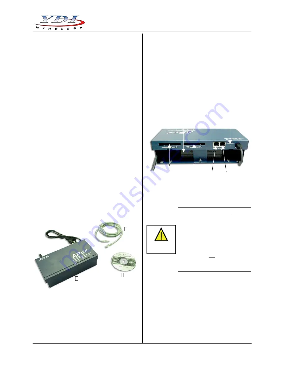
Figure 2 – AP-Plus Rear View
2. Connect your Ethernet cable to the Ethernet A or
Ethernet B RJ-45 jack on the rear of the unit. Note
that each RJ-45 jack has two LEDs. When looking
from the rear, the left LED indicates link up, and the
right LED shows network activity.
3. Connect the power cord to an AC wall-outlet to
power-up the AP-Plus.
4. When powered on, the AP-Plus will perform start-
up diagnostics characterized by an LED Sequence.
The LEDs (see Figure 3) will change colors in the
range of Amber, Red and Green. When the start-up
diagnostics are finished the AP-Plus will beep. The
unit will then be ready for normal operation. In this
condition, the Power LED is steady on. The
Ethernet A and B, and the Wireless A and B LEDs
will flash when there is network activity on the
corresponding AP-Plus network interface. If there is
no activity, the LEDs will be off.
1
1
33
44
PCMCIA Slot B
PCMCIA Slot A
Ethernet B Ethernet A
Restore Factory Defaults
110/220 VAC Power Supply
CAUTION
The Ethernet ports are
not
designed for Power Over Ethernet
(POE). The AP-Plus has its own
power supply to p5 VDC to
the unit. Please verify that no
source of power is applied to the
Ethernet ports.
If this happens the
Ethernet circuitry on the board
will blow
. Any damage caused by
this action will
not
be covered by
the factory warranty and will be a
billable repair.


