


3.2 Settings for Triggers at Preset Positions
3.2.2 Setting Triggers at Preset Positions
3
T
rigger
s
at Pr
e
s
et Po
s
ition
s
3-7
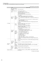
Output Position Compensation
Set the compensation distance in reference units from the reference position set in the out-
put position setting.
3.2.2
Setting Triggers at Preset Positions
This section describes the method to use the MEM_WR command to set high-speed outputs
from line drivers or normal outputs from photocouplers.
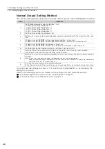
High-Speed Output Setting Method
This section describes the procedure to execute high-speed outputs with the MEM_WR com-
mand.
You can make the settings for steps 1, 2, 4, and 5 from the S or by executing the
MEM_WR command.
Refer to the following sections for details on the settings and then make the settings.
3.2.3 Setting Trigger Outputs at Preset Positions with the S
3.2.4 Making Settings with the MEM_WR Command
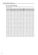
Size
Setting Range
Setting Unit
Default Setting
When Enabled
Classification
4
-2,147,483,648 to
2,147,483,647
Reference
units
0
Immediately
Setup
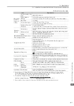
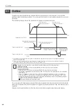
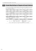
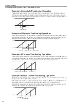
1. The polarity for signals output at preset positions can also be reversed with Pn512 (Output
Signal Inverse settings). Always check the setting of Pn512 before you allocate signal outputs
at preset positions.
2. If different signal logics are assigned to the same output terminals, the logic that is set for the
trigger at a preset position with the smallest number will be given priority.
3. If you set the output distance in reference units for the output function, make sure the output
distance is within the following distances.
•
If you use triggers at preset positions in combination with a rotational coordinate system, set
the output distance to between Pn87C and Pn87A.
•
If you use triggers at preset positions but do not use a rotational coordinate system, set the
output distance to between -2,147,483,648 and 2,147,483,647.
If you set the output distance to a value that exceeds the above ranges, an A.042 (Parameter
Combination Error) alarm will occur.
Important
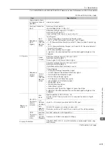
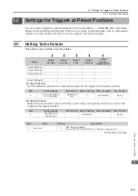
Step
Operation
1
Set the output positions in reference units.
2
Set the axis numbers, output signal allocations, and passing directions with the output function
selection.
3
If Pn660 is set to n.
0
, set the signal output width as a time in
μ
s.
If Pn660 is set to n.
1
, set the signal output width as a distance in reference units.
4
If Pn660 is set to n.
0
, set the output time in
μ
s.
If Pn660 is set to n.
1
, set the output distance as a distance in reference units.
5
Set the output position compensation as a distance in reference units.
6
Send the Setup Device command (CONFIG) to the SERVOPACK from the host controller.
The settings in the High-Speed Output Settings will be enabled.
7
Send the Turn Sensor ON command (SENS_ON: 23h) from the host controller to obtain the posi-
tion data.
Note: If you use an incremental encoder, the following step must also be performed.
Send the Zero Point Return command (ZRET: 3Ah) from the host controller, or use the Set Coordinates
command (POS_SET: 20h) to set REFE to 1.
8
Turn ON the servo, and send the motion command.
When the moving part of the machine passes a preset position, a high-speed output signal is out-
put.