

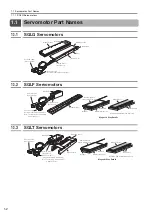


2.1 Selecting the Servomotor Capacity
2-2
2.1
Selecting the Servomotor Capacity
Contact your Yaskawa representative for information on the Servomotor capacity selection soft-
ware.
Refer to the following selection examples to select Servomotor capacities with manual calculations.
1.
Mechanical Specifications
2.
Operation Pattern
3.
Steady-State Force (Excluding Servomotor Moving Coil)
F
L
= {9.8
×
μ
×
(
m
W
+
m
T
)} +
F
= 9.8
×
0.2
×
(1 + 2) + 0 = 5.88 (N)
4.
Acceleration Force (Excluding Servomotor Moving Coil)
5.
Provisional Selection of Linear Servomotor
Selection Conditions
•
F
P
≤
Maximum force
×
0.9
•
F
s
≤
Maximum force
×
0.9
•
F
rms
≤
Rated force
×
0.9
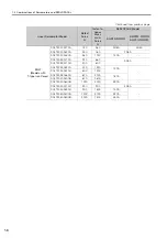
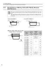
The following Servomotor Moving Coil and Magnetic Way meet the selection conditions.
•
SGLGW-60A253CP Linear Servomotor Moving Coil
•
SGLGM-60
C Linear Servomotor Magnetic Way
Item
Code
Value
Item
Code
Value
Load Mass
m
W
1 kg
Acceleration Time
t
a
0.02 s
Table Mass
m
T
2 kg
Constant-speed Time
t
c
0.36 s
Motor Speed
v
2 m/s
Deceleration Time
t
d
0.02 s
Feeding Distance
l
0.76 m
Cycle Time
t
0.5 s
Friction Coefficient
μ
0.2
External Force on Linear Motion Section
F
0 N
Load
Table
Moving Coil
Magnetic Way
v
t
Motor
s
peed (m/
s
)
Force (N)
Time (
s
)
ta
FP
FL
FS
tc
td
v
ta
2
0.02
FP
= (
mW
+
mT
)
×
+
FL
= (1 + 2)
×
+ 5.88 =
3
05.88 (N)