


3.5 SERVOPACK Overload Characteristics and Load Moment of Inertia
3-13
3
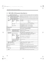
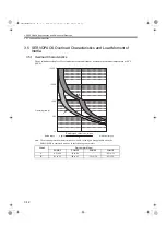
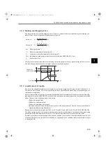
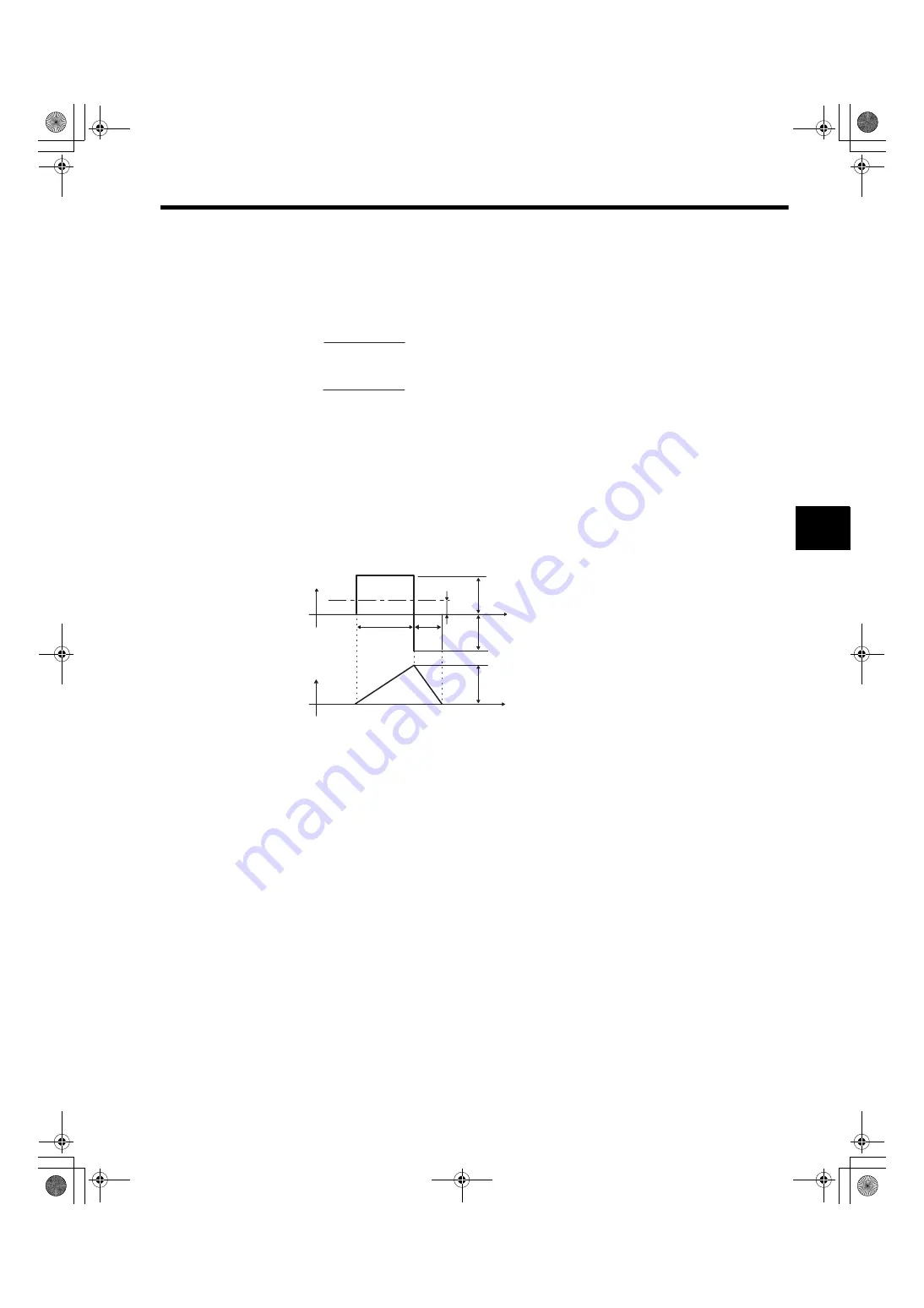
3.5.2 Starting and Stopping Time
The motor starting time (tr) and stopping time (tf) under a constant load are calculated using the following for-
mulas. Motor viscous torque and friction torque are ignored.
Calculate the torque from the motor current using servomotor torque constant
×
motor current (effective value).
The following figure shows the motor torque and motor speed timing chart.
3.5.3 Load Moment of Inertia
The size of the allowable load moment of inertia of a servomotor depends on the capacity, and is limited to 5 to
30 times the motor inertia. This value is provided strictly as a guideline and results may vary depending on ser-
vomotor drive conditions.
An overvoltage alarm is likely to occur during deceleration if the load moment of inertia exceeds the allowable
load moment of inertia. SERVOPACKs with a built-in regenerative resistor may generate a regeneration overload
alarm. Take one of the following steps if this occurs.
• Reduce the torque limit.
• Reduce the deceleration rate.
• Reduce the maximum motor speed.
• Install an externally mounted regenerative resistor if the alarm cannot be cleared. Contact your Yaskawa
Application Engineering Department.
Regenerative resistors are not built into 200 V for 50 W to 400 W and 100 V for 50 W to 400 W SERVOPACKs.
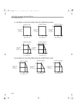
The following figures show the tentative relationship between the load moment of inertia and motor speed using
an example with a load moment of inertia 10 to 30 times the load moment of inertia at the motor shaft.
External regenerative resistors are required when this condition is exceeded or if the allowable loss capacity (W)
of the built-in regenerative resistor is exceeded due to regenerative drive conditions when a regenerative resistor
is already built in.
N
M
:
Motor speed (min
-1
)
J
M
:
Motor rotor moment of inertia (kg
x
m
2
)
J
L
:
Load converted to shaft moment of inertia (kg
x
m
2
)
T
PM
:
Instantaneous peak motor torque when combined with a SERVOPACK (N
x
m)
T
L
:
Load torque (N
x
m)
tr =
2
π
N
M
(J
M
+ J
L
)
60 (T
PM
−
T
L
)
[s]
tf =
2
π
N
M
(J
M
+ J
L
)
60 (T
PM
+ T
L
)
[s]
Starting time:
Stopping time:
Motor torque
(current amplitude)
Motor speed
tr
tf
N
M
T
PM
T
L
Time
Time
T
PM
SIEPS80000025.book 13 ページ 2004年10月25日 月曜日 午前11時57分


